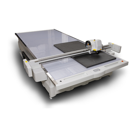
Esko Kongsberg XP User manual

Kongsberg XP
User Manual
10 - 2020 | XP

Kongsberg XP
Contents
1. Preface............................................................................................................................................................8
2. Change Record...............................................................................................................................................9
3. Introduction...................................................................................................................................................11
3.1. Welcome............................................................................................................................................... 11
3.2. FCC conformity statement...................................................................................................................11
4. Using this manual.........................................................................................................................................12
4.1. Main Sections...................................................................................................................................... 12
4.2. Name Styles and Symbols................................................................................................................... 13
4.3. Pictures and Illustrations.................................................................................................................... 13
4.4. Local Languages................................................................................................................................. 14
5. Safety Regulations....................................................................................................................................... 15
5.1. Introduction......................................................................................................................................... 15
5.2. Responsibilities................................................................................................................................... 15
5.2.1. The manufacturer...................................................................................................................... 15
5.2.2. The owner................................................................................................................................. 15
5.2.3. The operators............................................................................................................................16
5.3. Requirements to be met by operators.................................................................................................16
5.4. Definition of use..................................................................................................................................17
5.5. Warning sign explanation.................................................................................................................... 17
5.6. Attention areas...................................................................................................................................20
5.6.1. Mains power disconnection.......................................................................................................20
5.6.2. High voltage, laser radiation and moving parts........................................................................ 20
5.6.3. Loose clothing.......................................................................................................................... 21
5.6.4. Noise level.................................................................................................................................21
5.6.5. Ejection of parts when milling.................................................................................................. 21
5.6.6. Milling stop time........................................................................................................................21
5.6.7. i-Camera strobing light.............................................................................................................22
5.7. Safety devices.....................................................................................................................................23
5.7.1. Overview....................................................................................................................................23
5.7.2. Emergency stop button............................................................................................................ 23
5.7.3. Yellow/black tape......................................................................................................................24
5.7.4. Warning lamps on Y carriage....................................................................................................24
5.7.5. DynaGuard safety system..........................................................................................................25
5.7.6. Milling warning lamp................................................................................................................. 26
5.8. Protective equipment......................................................................................................................... 26
5.9. Procedures in case of Malfunctions....................................................................................................27
5.10. Check before operation..................................................................................................................... 27
ii

Contents
5.11. Residual risks..................................................................................................................................... 27
6. System Description..................................................................................................................................... 30
6.1. Naming Conventions........................................................................................................................... 30
6.2. Main Power Switch.............................................................................................................................. 31
6.3. Operators Panel...................................................................................................................................31
6.4. High Pressure Air System................................................................................................................... 33
6.5. Application Programs Available.......................................................................................................... 34
7. Basic Operations.......................................................................................................................................... 35
7.1. Introduction......................................................................................................................................... 35
7.2. Power On Sequence............................................................................................................................ 35
7.3. Reset Safety System........................................................................................................................... 36
7.4. Power Off Sequence........................................................................................................................... 36
7.5. Continue after Safety Break................................................................................................................ 37
8. Prepare for a Job.........................................................................................................................................38
8.1. Introduction.........................................................................................................................................38
8.2. Create Job.......................................................................................................................................... 38
8.3. Layer Setup.........................................................................................................................................38
8.4. Production Setup................................................................................................................................39
8.5. Speed Setting..................................................................................................................................... 39
8.6. Flute/Grain Direction.......................................................................................................................... 39
8.7. Vacuum Zone Selection...................................................................................................................... 39
8.8. Job Execution.................................................................................................................................... 40
8.9. Corrugated Production....................................................................................................................... 40
8.10. Milling Production.............................................................................................................................. 41
8.11. Make a Pen Plot.................................................................................................................................. 41
9. How To Procedures, Advanced................................................................................................................... 42
9.1. Optimize vacuum effect...................................................................................................................... 42
9.2. Cutting Thick Materials.......................................................................................................................43
9.3. Hard Board Production....................................................................................................................... 43
9.4. Multi-pass...........................................................................................................................................44
9.5. Job including Reverse Operation........................................................................................................44
9.5.1. Reverse Operation by Left and Right Rulers..............................................................................46
9.5.2. Reverse Operation by use of Camera....................................................................................... 46
9.5.3. Reverse Operation in combination with Step and Repeat......................................................... 47
9.6. Work with different Reference Point Settings.................................................................................... 48
9.7. MultiZone Production..........................................................................................................................48
9.7.1. MultiZone, Workflow.................................................................................................................. 50
10. System Setup............................................................................................................................................. 52
10.1. Introduction....................................................................................................................................... 52
10.2. Adjust X1 to X2 Angle........................................................................................................................ 53
10.3. Register Table Size............................................................................................................................53
iii

Kongsberg XP
10.4. Adjust Measuring Station Position.................................................................................................... 54
10.5. Set Ruler Position............................................................................................................................. 54
10.6. Set Main Reference Point..................................................................................................................54
10.7. Map Table Top Surface...................................................................................................................... 55
10.8. Calibrate Foot on Measuring Station................................................................................................. 56
10.9. Reference Points and Coordinate System......................................................................................... 56
10.10. Table Speed..................................................................................................................................... 58
10.11. Table Acceleration............................................................................................................................59
10.12. Jog Settings.....................................................................................................................................59
10.13. Set Table Top Reference..................................................................................................................60
10.14. Vacuum Setup..................................................................................................................................60
10.14.1. Vacuum Zone Configuration................................................................................................... 60
10.15. Milling Unit Setup............................................................................................................................. 62
10.16. Conveyor Belt Control...................................................................................................................... 62
10.16.1. Split Sheet Feed..................................................................................................................... 62
10.16.2. Sheet Feed Correction...........................................................................................................63
10.17. Board Size........................................................................................................................................ 63
11. Tool Configuration and Adjustment........................................................................................................... 64
11.1. Tool Configuration.............................................................................................................................. 64
11.2. Tool Names........................................................................................................................................ 66
11.3. Adjust Active Tool.............................................................................................................................. 67
11.4. Lag Settings (for Rotating Tools)........................................................................................................67
11.5. Tool Height Calibration.......................................................................................................................68
11.6. Rotation Adjustment (for Rotating tools)............................................................................................69
11.7. Center Offset Adjustment...................................................................................................................70
11.8. Tool Offset.......................................................................................................................................... 71
11.9. Knife angle calibration........................................................................................................................ 71
11.10. Maintain Tool List............................................................................................................................. 72
12. Tooling System........................................................................................................................................... 74
12.1. Introduction....................................................................................................................................... 74
12.2. Tool Handling and Care......................................................................................................................74
12.3. How to Replace a Tool....................................................................................................................... 75
12.4. Two or more tools of the same type..................................................................................................75
12.5. Measuring Station..............................................................................................................................76
12.6. HDU - Heavy Duty Unit.......................................................................................................................78
12.6.1. Crease Wheel ø150 mm............................................................................................................78
12.6.2. V-notch Knife Tool...................................................................................................................80
12.6.3. HD Knife Tool...........................................................................................................................85
12.6.4. Crease Adapter....................................................................................................................... 88
12.6.5. Perforation Wheel ø60 mm..................................................................................................... 88
12.6.6. Bevel Knife 45......................................................................................................................... 90
12.7. Foam Knife.........................................................................................................................................92
iv

Contents
12.8. Dual HDU - Dual Heavy Duty Unit.......................................................................................................94
12.8.1. Dual HDU HD Perf Position.......................................................................................................96
12.8.2. New mounting procedure for HD insert tools..........................................................................98
12.9. VariAngle unit...................................................................................................................................100
12.9.1. Introduction............................................................................................................................100
12.9.2. Safety precautions................................................................................................................ 100
12.9.3. Tool description......................................................................................................................101
12.9.4. Description of knife blade adapters.......................................................................................102
12.9.5. Tool adjustment.....................................................................................................................104
12.9.6. Basic modes of operation......................................................................................................105
12.9.7. Workflows, set-up and optimization.......................................................................................107
12.9.8. Advanced operations............................................................................................................. 108
12.9.9. Work area limitations.............................................................................................................. 111
12.9.10. Material lift............................................................................................................................112
12.10. HPMU - High Power Milling Unit.......................................................................................................112
12.10.1. Introduction........................................................................................................................... 112
12.10.2. Tool Head description........................................................................................................... 113
12.10.3. Safety issues......................................................................................................................... 115
12.10.4. Precautions........................................................................................................................... 117
12.10.5. Milling advice.........................................................................................................................121
12.10.6. Cleaner Device......................................................................................................................124
12.10.7. Bits and Bit Change.............................................................................................................. 124
12.10.8. Chuck Change and Cleaning................................................................................................. 126
12.10.9. Bit Slipping, Chuck Change.................................................................................................. 130
12.10.10. Bit Length and Position...................................................................................................... 130
12.10.11. Tool Adjustment................................................................................................................... 131
12.10.12. Table Top and Tool Height Adjustment................................................................................ 131
12.10.13. Miscellaneous......................................................................................................................132
12.10.14. LubriCool (MultiCUT-HP only).............................................................................................. 133
12.11. Chiller no 1 (blue top) for HPMU....................................................................................................... 136
12.11.1. Introduction........................................................................................................................... 136
12.11.2. Chiller Heater, Operation....................................................................................................... 137
12.11.3. Chiller, Error Conditions........................................................................................................ 139
12.12. Chiller 2016 / Chiller 2020 for HPMU................................................................................................139
12.12.1. Introduction...........................................................................................................................139
12.12.2. Startup................................................................................................................................. 140
12.12.3. Error Conditions....................................................................................................................141
12.13. VibraCut..........................................................................................................................................142
12.14. Rigid Material Knife (RM Knife Tool)................................................................................................ 144
12.15. HiForce Knife.................................................................................................................................. 145
12.16. Psaligraphy Knife............................................................................................................................ 148
12.17. PressCut..........................................................................................................................................149
12.18. RotaCut...........................................................................................................................................152
v
Kongsberg XP
12.19. Braille Tool...................................................................................................................................... 155
12.20. CorruSpeed Knife........................................................................................................................... 159
12.20.1. Tool adjustment.................................................................................................................... 161
12.21. Braille Tool.......................................................................................................................................161
12.22. Drill / Pen Tool................................................................................................................................ 166
12.23. Drill Tool......................................................................................................................................... 168
12.24. Ballpoint Pen.................................................................................................................................. 169
12.25. Measuring Foot...............................................................................................................................170
12.26. Laser Pointer..................................................................................................................................170
13. Maintenance............................................................................................................................................... 171
13.1. General...............................................................................................................................................171
13.2. Daily Maintenance............................................................................................................................. 171
13.3. Weekly Maintenance......................................................................................................................... 171
13.4. Monthly Maintenance........................................................................................................................172
13.5. Maintenance, External Equipment.................................................................................................... 177
13.6. Maintenance, Take Up Unit............................................................................................................... 177
13.6.1. General....................................................................................................................................177
13.6.2. Spare Parts............................................................................................................................ 178
14. Fuse Replacement.....................................................................................................................................179
14.1. MPU fuses......................................................................................................................................... 179
14.2. X1..................................................................................................................................................... 180
14.3. X2......................................................................................................................................................181
14.4. Y.......................................................................................................................................................183
14.5. P1/P2 fuses...................................................................................................................................... 184
14.6. Fuses on various tools..................................................................................................................... 186
14.7. Chiller fuse, Hyfra (blue top)............................................................................................................. 187
14.8. Heater for Chiller Fuse..................................................................................................................... 188
14.9. Chiller 2016 / Chiller 2020 Fuse replacement................................................................................... 188
14.10. Sound Insulating Box, Circuit Breaker for fan................................................................................. 189
14.11. TakeUp Unit, Fuse replacement...................................................................................................... 190
14.12. Motorized Roll Feeder, Fuse replacement....................................................................................... 191
15. Roll Feeder.................................................................................................................................................193
16. Collector Basket........................................................................................................................................194
17. TakeUp Unit................................................................................................................................................195
17.1. Introduction.......................................................................................................................................195
17.2. Machine Description......................................................................................................................... 196
17.3. Safety................................................................................................................................................197
17.4. Features and components................................................................................................................199
17.5. General operation............................................................................................................................ 200
17.6. Applying Winding Material................................................................................................................ 201
17.7. Start the TakeUp Unit...................................................................................................................... 202
vi

Contents
17.8. Using the Autogrip Shaft................................................................................................................. 203
18. MRF Quick start guide.............................................................................................................................. 206
19. MRF Weight list.........................................................................................................................................207
20. Vacuum Cleaner.......................................................................................................................................208
20.1. Vacuum Cleaner, Zefiro................................................................................................................... 208
20.1.1. How to use.............................................................................................................................208
20.2. Vacuum Cleaner, High-capacity, TB ESKO.......................................................................................210
20.2.1. How to use............................................................................................................................ 210
20.3. Compact Vacuum Cleaner............................................................................................................... 213
20.3.1. How to use.............................................................................................................................213
21. Install Software.........................................................................................................................................215
22. Frequently Asked Questions.................................................................................................................... 216
22.1. Machine............................................................................................................................................216
22.2. Tools................................................................................................................................................216
22.3. iPC................................................................................................................................................... 217
vii

1Kongsberg XP
1. Preface
User Manual
for
Kongsberg XP
running i-cut Production Console
Note: We remind you that only the Esko Staff, or persons having received appropriate training, are
allowed to handle, manipulate or do repairs on the system.
Note: Original instructions are in English. Instructions in other languages are translations of original
instructions.
Disclaimer: Do not operate this equipment in an EU member State if the Instructions are not written in
that State's language. Contact Esko if a translation is needed.
©Copyright 2020, Esko-Graphics Kongsberg AS, Norway
All Rights Reserved.
This copyright does not indicate that this work has been published.
This material, information and instructions for use contained herein are the property of Esko-Graphics Kongsberg AS. There
are no warranties granted or extended by this document. Furthermore, Esko-Graphics Kongsberg AS does not warrant,
guarantee or make any representations regarding the use, or the results of the use of the system or the information contained
herein. Esko-Graphics Kongsberg AS shall not be liable for any direct, indirect, consequential or incidental damages arising
out of the use or inability to use the system or the information contained herein. The information contained herein is
subject to change without notice. Revisions may be issued from time to time to advise of such changes and/or additions.
No part of this system may be reproduced, stored in a data base or retrieval system, or
published, in any form or in any way, electronically, mechanically, by print, photoprint, microfilm
or any other means without prior written permission from Esko-Graphics Kongsberg AS.
This document supersedes all previous dated versions.
Correspondence regarding this publication should be forwarded to:
Global support
Esko-Graphics Kongsberg AS
Document no: D3621
Part no: 32597502
Esko-Graphics Kongsberg AS
www.esko.com
P.O.Box 1016, NO-3601 Kongsberg, NORWAY
Tel.: +47 32 28 99 00
8

2
Kongsberg XP
2. Change Record
Date
dd-mm-yy
By Description
03-02-2017 jhbe TakeUp Unit, information added
18-04-2017 jhbe Measuring station operation, information added.
20-04-2017 jhbe Braille tool description added
20-04-2017 jhbe Bevel 45 tool adapter description added
03-07-2017 jhbe Tool Insert Position, limitation information added.
07-08-2017 jhbe The importance of Braille tool height adjustment
has been emphasized.
30-08-2017 jhbe Braille tool info added.
06-11-2017 jhbe Droplets from cooling water connections,
description added
17-11-2017 jhbe Board Stacker, information added.
01-12-2017 jhbe Motorized Roll Feeder, information added
17.03.2018 DHO Motorized Roll Feeder, information removed. Work
area information added.
11.05.2018 DHO Operator panel upgrade June-September 2018
included + misc.
19.09.2018 DHO Section for Underside Camera added. Reverse
operation by use of camera added.
30.11.2018 DHO 2nd Fast Tool Enabler for Cx (and XP) and misc.
28.02.2019 DHO Safety precautions updated. Feeder/Stacker
procedures updated.
10.04.2019 DHO 2nd Fast Tool Enabler renamed to Fast Tool
Adapter. Caster wheels. Feeder suction arm.
29.04.2019 DHO Statement for Warp vs. Material Stacker updated.
04.07.2019 DHO Dual HDU added
26.08.2019 DHO Motorized Roll Feeder section updated.
20.09.2019 DHO MRF Quick start and Weight list added.
25.09.2019 DHO Monthly Maintenance updated.
20.02.2020 DHO Safety sections + misc. updated
06.03.2020 DHO Updated for Chiller 2020
9

2Kongsberg XP
Date
dd-mm-yy
By Description
02.04.2020 DHO Safety section updated
08.06.20 DHO FCC conformity statement added
14.09.2020 DHO Minor update
22.09.2020 DHO Warning sign "Sharp knives" added
27.10.2020 DHO VariAngle unit included
10

3
Kongsberg XP
3. Introduction
3.1. Welcome
Welcome to the User Manual for Kongsberg XP running iPC.
This manual will provide a complete and detailed description of all Cutting Table functions.
There is a separate user manual for i-cut Production Console (iPC). Thus, actual GUI functions will be
referenced in this manual, but the complete and comprehensive description is available in the User
Manual for i-cut Production Console.
This manual is aimed for operators of Kongsberg Cutting Tables and people preparing files for such
equipment.
Another source for information is the manual: Get the best out of iPC 2.2.
Note: Some of the functions and equipments described in this manual are optional.
3.2. FCC conformity statement
This machine complies with CFR 47 part 15 of the FCC Rules. Operation is subject to the following two
conditions:
1. This device may not cause harmful interference
2. This device must accept any interference received, including interference that may cause
undesired operation
11

4Kongsberg XP
4. Using this manual
4.1. Main Sections
The manual is divided into the following Main Sections:
Safety Regulations
• All safety related issues are discussed.
System Description
• This chapter provides basic knowledge about the machine.
Basic Operations
• This chapter provides basic knowledge about how to operate the machine.
Prepare for a Job
• A typical workflow is described, with detailed information about each step.
How to Procedures, Advanced
Optional functions for the advanced user:
•Cutting Thick Materials - advices.
•Hard Board Production - advices.
•Multi Pass Creasing or Milling - how to.
•Jobs including Reverse Operations - how to.
•Work with different Reference Point Settings - how to.
•MultiZone Production - how to.
Work with Registration Marks
• A step by step workflow.
System Setup
• Settings specifying the general behaviour of the system.
Tool Configuration and Adjustment
• General information about the tooling and adjustment of tools.
12

4
Kongsberg XP
Tooling System
• Tool descriptions.
Maintenance
• This chapter describes maintenance to be carried out by the customer.
Fuse Replacement
• Fuse location and specification.
Appendices
•Roll Feeder - basic information.
•Vacuum Cleaner - basic information.
4.2. Name Styles and Symbols
Name or style Description
Pop-up dialog This is the dialog that appears when you click the Right
mouse button.
Start button The italic style indicates this is a button on the Operator
Panel.
OK The bold style indicates this is a button or function in the
GUI.
Maintenance Link to topic.
Menu Bar->Edit-> Options
Menu selection: From Menu Bar, select Edit and then
Options.
This symbol indicates that the function depends upon actual
hardware.
If hardware is not available, this functions is hidden.
This symbol indicates that the function is license
dependant.
4.3. Pictures and Illustrations
Orientation
In this document, pictures and illustrations related to the Cutting Table are viewed as shown here:
13

4Kongsberg XP
4.4. Local Languages
This manual is available in a wide range of local languages.
Screen pictures and illustrations remain in English language.
For safety related illustrations, text is translated.
14

5
Kongsberg XP
5. Safety Regulations
5.1. Introduction
The XP table is designed to conform to Safety Regulation standards.
Dangers are designed away as far as practically possible. Nevertheless, all hazards could not be
removed. This section must be read carefully to understand the remaining risks, warning symbols,
responsibilities, requirements and safety precautions.
In particular, operating the table can involve hazards if:
• The operator does not follow the operating instructions.
• The table is used for non-intended purposes.
Special attention should be paid upon the following:
• Be careful when handling tools with knife blades. Knives are extremely sharp.
• Be careful when operating the milling tool. The milling spindle needs a few seconds to stop, and any
contact with a rotating milling bit is very dangerous.
• Use appropriate techniques and tools when handling heavy materials.
• The machine has fast moving parts like the traverse and tool head. Stay away from the danger zone
during operation.
• The system is equipped with a class II laser pointer. Do not stare directly into it. That can damage
your eyes.
In addition to the safety regulation described below, there are safety warnings in the respective topics.
5.2. Responsibilities
5.2.1. The manufacturer
The manufacturer is responsible for delivering the system according to safety regulation standards.
5.2.2. The owner
The owner is responsible for:
• Ensuring that the system is used for its intended use only
• Ensuring that only authorized and trained personnel operate the system
15

5Kongsberg XP
• Preventive maintenance as described in the maintenance section of the user manual
• That the local Regulations regarding installation and operation are fulfilled
• Ensure that safe work procedures and awareness of potential hazards are periodically reviewed and
enforced
5.2.3. The operators
The operators are responsible for:
• Operating the system only when it is in a flawless state
• Operating the system according to operating instructions
• Ensuring that no unauthorized personnel come close to the system.
5.3. Requirements to be met by operators
Personnel operating the system must:
• Be adequately trained.
• Have read and understood the instructions described in safety regulation as well as any other safety
warnings.
Training will be given to operator(s) nominated by the customer by the Esko service engineer as part
of the system installation.
The training covers:
• Safety regulations
• Start-up and shut-down procedures
• Online help / user manuals
• Set-up procedures
• Adjustment procedures
• Workflow
• Maintenance
For additional training courses, contact Esko global support.
Un-trained personnel shall under no circumstances be allowed to operate the system!
Note: We remind you that only the Esko staff, or persons having received appropriate training, are
allowed to handle, manipulate or do repairs on the system.
In particular, milling operations shall only be performed by properly trained operators due to the
dangerous nature of the milling tool.
16

5
Kongsberg XP
5.4. Definition of use
The system is designed for use within applications, materials, tools and workflow as described in the
user manual for iPC. In the user manual for cutting table, intended use is described in the following
sections:
•Basic Operations
•Prepare for a Job
•How to Procedures, Advanced
Any other use is considered as non-intended use. Examples of non-intended use:
• Operation by operators not meeting the requirements as described above.
• Unauthorized modifications (bridging safety devices, removing covers etc.)
• Deliberately avoiding the DynaGuard safety system by reaching under the lower beam to avoid
detection.
• Utilizing accessories other than those specified by Esko.
• Operating or maintaining the machine or any of its accessories under the influence of drugs, alcohol
or medication that could impair your judgment and vigilance.
Non-intended use may cause:
• Health hazards and injuries.
• Damage to the system.
• Incorrect functionality.
• Damage to work materials.
Note: Esko is not liable for any damage resulting from such non-intended use.
5.5. Warning sign explanation
High voltage warnings
• Main Power Unit (MPU) and vacuum pump
Do not open cover on either MPU or vacuum pump before mains is
disconnected from cutting table and vacuum pump.
Note: Different instruction for Cxx and Xxx.
• IBAG inverter
Do not open cover on IBAG inverter before mains is disconnected from cutting
table.
Note: Different instruction for Cxx and Xxx.
17

5Kongsberg XP
•Chiller
Do not open cover on chiller before mains is disconnected from cutting table.
Note: Different instruction for Cxx and Xxx.
• Vacuum cleaner
Do not open cover on vacuum cleaner before mains is disconnected from
cutting table.
Note: Different instruction for Cxx and Xxx.
Note: Equipment with high voltage may be opened by authorized personnel only.
Caution, laser
LASER RADIATION
DO NOT STARE INTO BEAM
DIODE LASER
MAX OUTPUT 1 mW
WAVELENGTH 650-660 nm
EN 60825-1: 1991+A11:1996
CLASS II LASER PRODUCT
AVOID EXPOSURE
Laser radiation emitted from this aperture
General warning
Milling tools
Milling tools require skill, and must be run by
QUALIFIED OPERATORS ONLY
This is based on
• Safety issues
• Protection of the equipment
• Taking care of expensive materials
Hand Squeeze
Potential areas with a risk of being squeezed are marked with the Hand Squeeze
sign.
These areas are:
• Between X-axis end stopper and traverse wagon.
18

5
Kongsberg XP
Sharp knives
Potential risk of being cut by sharp knives.
Moving Parts
Potential areas with a risk of being hit by Moving Parts are marked with the
Moving Parts sign.
These areas are:
• Both traverse ends.
• Y carriage.
• Tool head(s).
Do not Touch
Potential areas with a risk of being squeezed are marked with the Do Not Touch
sign.
These areas are:
• Between Y carriage and rack
• Between the table top and the moving traverse.
• Underneath the tool head.
Hearing Protection
The Hearing Protection symbol indicates areas where the use of hearing
protection is compulsory.
Eye Protection
The Eye Protection symbol indicates areas where the use of eye protection is
compulsory.
Do not leave the machine running if the vacuum cleaner can
be over-filled. This might cause damage, or in worst case a
fire if the suction house is clogged.
See also Safety issues on page 115 in the section for
milling.
19

5Kongsberg XP
Knife blades and milling bitsare extremely sharp.
This symbol is used in documentation to indicate operations where there is risk of
being injured.
Additional warning signs are found in relevant sections.
5.6. Attention areas
5.6.1. Mains power disconnection
The main power switch on the operator station is intended for daily power on/off
To permanently disconnect mains power, e.g. for maintenance, use a lockable on/off switch at the
power line if available, or remove the plug from the wall outlet. In addition, turn off the main power
switch.
Note: A lockable on/off switch on the power line may be required by local regulations, but is part of
the site preparation, site owner’s responsibility, not included in the Kongsberg system delivery unless
agreed.
5.6.2. High voltage, laser radiation and moving parts
20
Other manuals for Kongsberg XP
1
Table of contents
Other Esko Cutter manuals

Esko
Esko Kongsberg XP User manual

Esko
Esko Kongsberg V-Series User manual

Esko
Esko Kongsberg XN IPC 2.0 User manual

Esko
Esko Kongsberg C series User manual

Esko
Esko Kongsberg XE10 User manual

Esko
Esko Kongsberg C series Specification sheet

Esko
Esko Kongsberg XL User manual

Esko
Esko Kongsberg XE User manual