Essilor Instruments APH 550 User manual

Automatic Phoropter
Maintenance Manual
V1 –09/2016

Contents
1External and Internal Structural Diagram..................................................................1
2Block Diagram ................................................................................................................6
3Connection Diagram.......................................................................................................7
4Wiring Diagram..............................................................................................................9
5Troubleshooting ............................................................................................................12
6Cleaning of Measuring Windows ................................................................................40
7Maintenance Mode .......................................................................................................41
8Replacement procedure of each unit...........................................................................50
9Rewriting procedures of the Software of APH 550 ....................................................73

1
1External and Internal Structural Diagram
1-1 External structural diagram (head)
No.
Name
No.
Name
No.
Name
1
LD case assy
6
Head rest adjustment knob assy
11
Measuring window 2
2
Face shield R assy
7
Near point chart fixing knob
12
Measuring window 3
3
Face shield L assy
8
Joint fixing knob assy
13
VD check windows
4
Head rest
9
Joint block assy
5
Cover for hiding screw
10
Measuring window 1
12
12.
6
7
1
11
2
3
9
4
13
13
10
5
8

2
1-2 Internal structural diagram (head)
No.
Name
No.
Name
No.
Name
1
Motor control board assy
6
LED board assy for lighting the
left side near point chart
11
PD assy
2
Infrared communication board assy
12
Leveling adjustment knob assy
3
Right side motor drive board assy
7
LD-R assy
13
Chart stopper
4
Left side motor drive board assy
8
LD-L assy
14
Head unit peripheral harness
5
LED board assy for lighting the right
side near point chart
9
VD-R assy
15
Infrared ray harness
10
VD-L assy
16
Motor drive unit harness
2
14
5
6
13
15
3
4
7
8
9
10
14
12
11
15
16
1

3
1-3 External structural diagram (controller)
No.
Name
1
LCD case 1 assy
2
LCD case 2
3
Operation unit case assy
4
Body case 1
5
Body case 2
6
Printer cover
7
Open switch
8
Operation dial assy
9
LCD panel assy
9
1
8
3
4
6
2
7
5

4
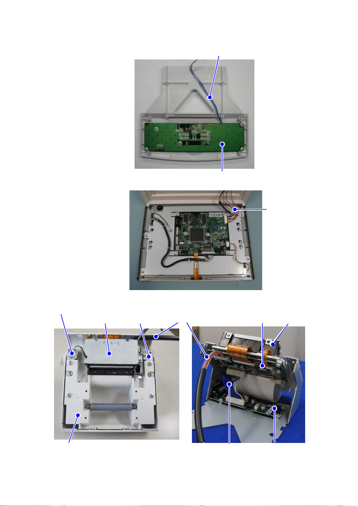
1-4 Internal structural diagram (controller)
No.
Name
1
Control board assy
2
Operation board assy
3
Printer control board assy
4
Relay board assy
5
Printer case
6
LCD panel assy
7
Thermal printer

5
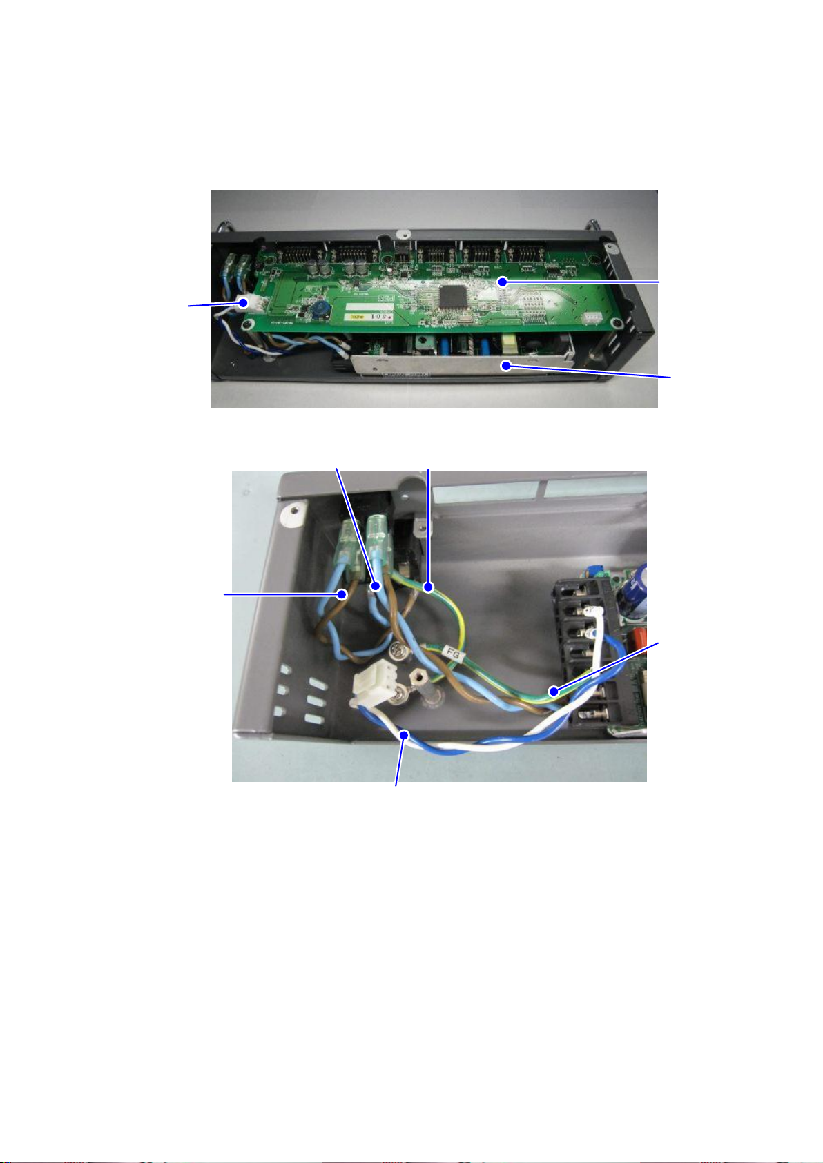
1-5 External structural diagram (relay box)
1-6 Internal structural diagram (relay box)
No.
Name
1
Power case
2
Power switch
No.
Name
1
Communication board assy
2
Switching power supply assy
1
2
6
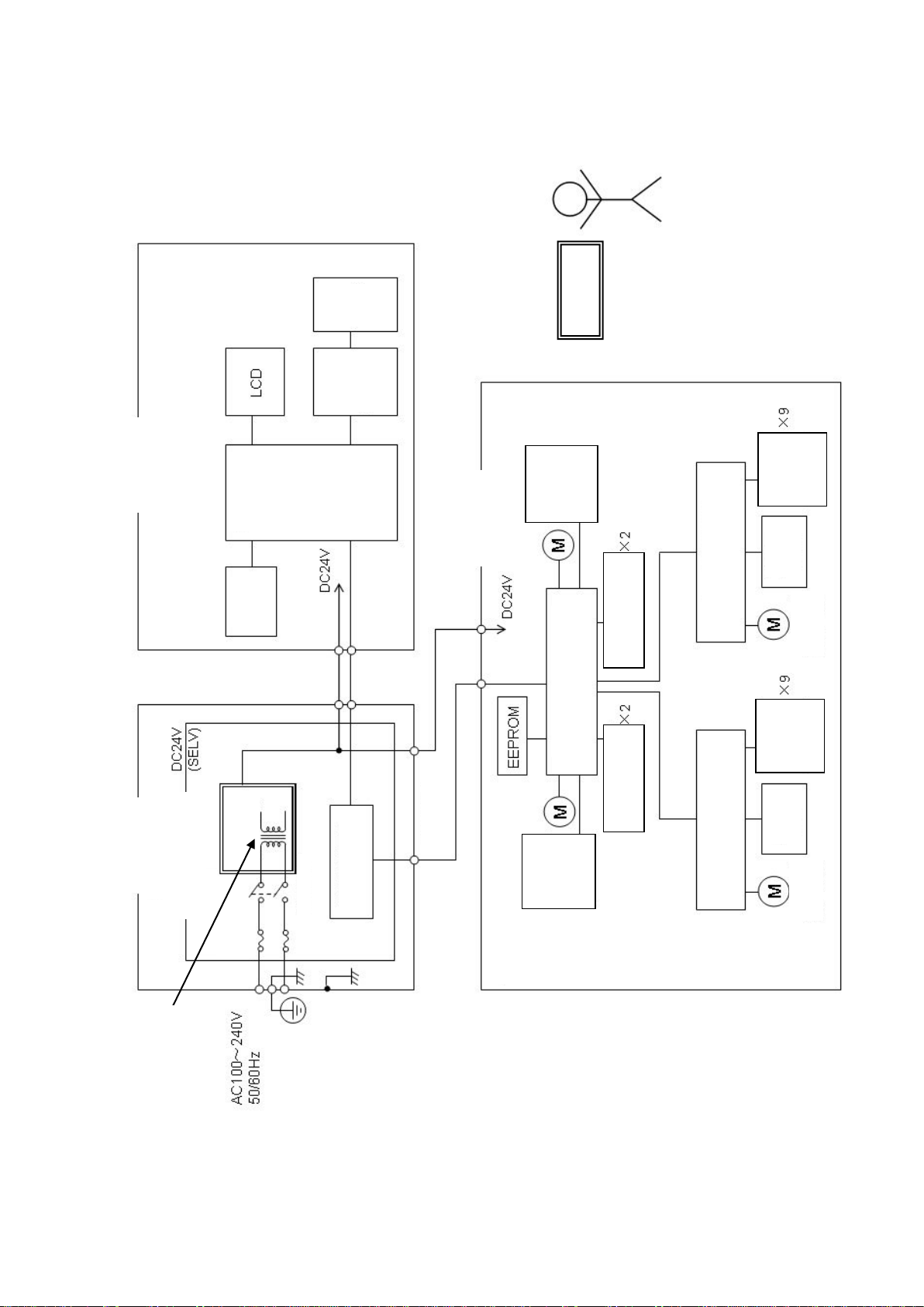
2Block Diagram
Enclosure
Control unit
Operation
unit
Control
circuit
Printer
Printer
drive
circuit
Reinforced insulation
Head rest
Enclosure
Position
detecting
sensor
Right chart LED
Left chart LED
Motor control circuit
Position
detecting
sensor
Head
unit
Interface
Enclosure
Power supply
box unit
Fuse
Power switch
Communication
control circuit
Basic insulation
Switching supply
Reinforced insulation
between primary and
secondary
Left motor drive circuit
Illumination
LED
Position
detecting
sensor
Right motor drive circuit
Illumination
LED
Position
detecting
sensor
Lens disk
motor ×9
Lens disk
motor ×9

7
3Connection Diagram

8

9
4Wiring Diagram
4-1 Head
Left motor drive board assy
Position detecting sensor harness
Motor drive unit harness
Sensor relay harness
Right motor drive board assy
Position detecting sensor harness
VD-L assy
LED harness for
lighting eyeball
LED board assy for
lighting left
eyeball
LED board assy for
lighting right eyeball
VD-R assy
LED harness for
lighting eyeball
10
4-2 Controller
Operation board assy
Operation harness
Control
printer harness
Printer case
Thermal
printer
Printer flame
harness
Flame
harness
Control printer
harness
Printer control
board assy
Relay board assy
Thermal
printer
Printer
harness
11
4-3 Relay box
Communication
board assy
SWPS output
harness
Switching power
supply assy
Inlet earth harness
SWPS input harness
Power supply
SW harness
Earth harness 2
SWPS output
harness

12
5Troubleshooting
5-1 General description of boards
5-2 Error message “Connecting Failure”appears
5-3 Error message “Right (Left) Communication Error”appears
5-4 Error message “Printer Overheated”appears
5-5 Error message “Paper Empty”appears
5-6 Error message “Printer Cutter Error”appears
5-7 Error message “PD Error”appears
5-8 Error message “WD Error”appears
5-9 Error message “Right Disk ○Error”or “Left Disk ○Error”appears
5-10 Error message “Right Lens 4-5 Error”or “Left Lens 4-5 Error”appears
5-11 Error message “Right Lens 6 In Error”or “Left Lens 6 In Error”appears
5-12 Error message “Right Lens 6 Out Error” or “Left Lens 6 Out Error”appears
5-13 Error message “Error 7”appears
5-14 Error message “Error 8”appears
5-15 Nothing is displayed on screen when turning power on
5-16 No response when operating operation switches or dial switch on controller
5-17 Touch panel does not work
5-18 Measurement result is not printed out/ printout is not normal
5-19 LED for lighting eyeball does not light up
5-20 LED for lighting neat point chart does not light up
5-21 Cannot switch chart
5-22 Cannot communicate with autoref, lensmeter or PC
5-23 Power indicator of relay box does not light up
5-24 Other error message

13
5-1 General description of boards
This product is composed with the peripheral devices, mainly such as 5 control boards, LED and
sensor etc.
The micro controller is mounted on 5 control boards below and they work with the instruction
from the control board.
When the red LED on the communication board is lighted, it is in the process of the program
rewriting of the control board.
The functions of the main boards are shown below.
1.
Control board assy
: LCD control, touch panel control
2.
Operation board assy
: Operation switch control, power indicator control
3.
Printer control board assy
: Printing of the printer, feeding paper control, cutter control
4.
Motor control board assy
: Motor control and LED control in the main unit, infrared
communication control
5.
Communication board assy
: Communication control with an autoref, lensmeter and PC

14
5-2 Error message “Motor not connected”appears
Main causes when error massage “Motor not connected”appears:
・Failure of communication cable between head and relay box
・Failure of motor control board assy
・Failure of communication board assy
Check the connection of the communication cable.
NO
YES
Replace the communication cables which connect the head
and the relay box, and the controller and the relay box.
OK
“Motor not connected”appears.
Replace the
communication cable.
Is the display of the LCD switched depending
on the operation of the controller?
(Go to “NO”if nothing is displayed on the LCD.)
YES
NO
Connect the connector for the controller of the relay box and the communication
connector of the head, and the connector for the head unit of the relay box and the
communication connector of the controller each with the communication cables.
Is the display of the LCD switched depending
on the operation of the controller?
(Go to “NO”if nothing is displayed on the LCD.)
Replace the communication board assy.
NO
YES
Does "Motor not connected" still appear?
Replace the motor
control board assy.
Does "Motor not connected" still appear?
OK
NO
YES

15
5-3 Error message “Right (Left) Communication Error”appears
Main causes when error message “Right (Left) Communication Error”appears:
・Failure of harness of motor drive unit
・Failure of motor control board assy
・Failure of right (left) side motor drive board assy
NO
YES
“Right (Left) Communication Error”appears.
OK
NO
Replace the harness of
the motor drive unit.
Is the harness of the motor drive unit normal?
Connect the connector for connecting the LD-L assy of the motor
control board assy (CN103) and CN302 of the right motor drive
board assy, and the connector for connecting the LD-R assy of the
motor control board assy (CN102) and CN302 of the left motor
drive board assy each with the harnesses of the motor drive unit.
Does “Right (Left) Communication
Error”still appear?
YES
“Right (Left) Communication Error”does not appear
and "Left(Right) Communication Error" appears.
YES
Replace the right (left) motor drive board assy.
Replace the motor control board assy.
Does “Right (Left)
Communication Error”appear?
YES
NO
NO

16
5-4 Error message “Printer Overheated”appears
Main causes when error message “Printer Overheated”appears:
・Failure of thermal printer
・Failure of printer control board assy
“Printer Overheated”appears.
Replace the thermal printer.
Replace the printer control board assy.
OK
Does “Printer Overheated”still appear?
NO
YES

17
5-5 Error message “Paper Empty” appears
Main causes when error message “Paper Empty”appears:
・No printer papers in printer
・Failure of thermal printer
・Failure of printer control board assy
“Paper Empty”appears.
Does “Paper Empty”still appear?
Replace the printer control board assy.
OK
Are the printer
papers set properly?
NO
YES
Reset the papers.
YES
NO
Replace the thermal printer.

18
5-6 Error message “Printer Cutter Error”appears
Main causes when error message “Printer Cutter Error”appears:
・A printer paper is stuck in cutter portion
・Failure of thermal printer
・Failure of printer control board assy
Are the printer papers
stuck in the printer portion?
YES
NO
“Printer Cutter Error”appears.
YES
OK
Does “Printer Cutter Error”still appear?
Remove the paper.
NO
Replace the thermal printer.
Replace the printer control board assy.
Table of contents
Other Essilor Instruments Medical Equipment manuals

Essilor Instruments
Essilor Instruments Retina 800 User manual

Essilor Instruments
Essilor Instruments Vision-R 800 User manual

Essilor Instruments
Essilor Instruments Retina 550 User manual

Essilor Instruments
Essilor Instruments Vision-C 600 User manual

Essilor Instruments
Essilor Instruments EyeViz 300 User manual

Essilor Instruments
Essilor Instruments Mr Blue 2.0 Sun and Sport Edition User manual

Essilor Instruments
Essilor Instruments VISION-R 700 User manual

Essilor Instruments
Essilor Instruments DELTA User manual

Essilor Instruments
Essilor Instruments VISIOSMART 500 User manual

Essilor Instruments
Essilor Instruments AKR 800 User manual


