NoiseKen 13-00005A User manual

INSTRUCTIONMANUAL
Emergency Stop Box
13-00005A
NOISE LABORATORY CO., LTD.
Edition 1.02
AEY00043-00E-0C
MODEL

NOTICE
•The contents of this instruction manual (the “Manual”) are subject to change
without prior notice.
•No part of the Manual may be reproduced or distributed, in any form or by
any means, without the authori ation of Noise Laboratory Co., Ltd. (the
“Company”).
•The contents of the Manual have been thoroughly examined. However, if you
find any problems, misprints, or missing information, please feel free to
contact our sales agent who you purchased our product from.
•The Company assumes no responsibility for any loss or damage resulting
from improper usage, failure to follow the Manual, or any repair or
modifications of this product undertaken by a third party other than the
Company or the agent authori ed by the Company.
•
The Company assumes no responsibility for any loss or damage resulting
from remodeling or conversion solely undertaken by the user.
•
Please note that the Company cannot be held responsible for any
consequences arising from the use of this product.
1
Before connection of other system components to this
device, be sure to turn off each component and check to see
that no component is operating.
Failure to observe this may cause an electric shock or lead to a failure of this
device and other connected devices.
A person who has a pacemaker on should not operate the
Unit and also should not enter the area where it is operating.
It may result in a fatal or serious accident.
The Unit cannot be used in an explosive area, fire prohibited
area, etc.
Use of the Unit in such an area is liable to cause combustion or ignition.
1. IMPORTANTSAFETYPRECAUTIONS
The following instructions are very important for safe handling of the emergency
stop box 13-00005A (hereinafter “the Unit”). They must be kept strictly to prevent
users of the Unit from receiving harm or damage through using the Unit. Read them
carefully before use.
A number of safety recommendations are listed in the later chapter
"BASIC SAFETY PRECAUTIONS". Be sure to read them before test
environment settings, connecting relating equipment and testing.

Memorandum
2

3
2. APPLICATIONFORMFORINSTRUCTIONMANUAL
We place an order for an instruction manual.
Model:13-00005A
Serial No.:
Applicant:
Company name:
Address:
Department:
Person in charge:
Tel No.:
Fax No.
Cut off this page “APPLICATION FORM FOR INSTRUCTION
MANUAL” from this volume and keep it for future use with
care.
When an INSTRUCTION MANUAL is required, fill in the above Application Form and
mail or fax it to the following sales department of our company.
To: Noise Laboratory Co., Ltd.
1-4-4 Chiyoda, Chuo-ku, Sagamihara City,
Kanagawa Pref., 252-0237 Japan
Tel: +81-(0)42-712-2051 Fax: +81-(0)42-712-2050
Cut
line

Memorandum
4

5
3. PREFACE
We thank you very much for your purchase of our Emergency Stop Box
13-00005A (hereinafter “the Unit”). This instruction manual (“the
Manual”) contains how to use the Unit and other important information.
In order to obtain the highest performance from the Unit, thoroughly
understand the contents of the Manual and use as ready reference for
operation.
The Manual was prepared so that any person who can observe the prescribed instruction
method and operating precautions may safely handle and fully utilize the Unit.
Keep the Manual by your side or other proper location so that it may be readily available
when using the Unit.
3-1. Feature
This product is a system overall safety device which interrupts the output path from SG (signal
generator) and send instructions to the amplifier to turn off output and NETS immunity system
software for stopping output from SG, when the interlock or emergency stop signal has been
detected.

6
4. CONTENTS
1. IMPORTANT SAFETY PRECAUTIONS ................................................................................ 1
2. APPLICATION FORM FOR INSTRUCTION MANUAL ....................................................... 3
3. PREFACE ................................................................................................................................ 5
3-1. F
EATURE
........................................................................................................................... 5
4. CONTENTS ............................................................................................................................. 6
5. BASIC SAFETY PRECAUTIONS ........................................................................................... 7
5-
--
-1. S
YMBOLS OF
H
AZARD
......................................................................................................... 7
5-
--
-2. S
YMBOLS OF
I
NSTRUCTION
,
W
ARNING AND
C
AUTION
............................................................ 7
6. INCLUDED ACCESSORIES .................................................................................................. 13
7. CONTROLS AND INDICATORS ........................................................................................... 14
8. OPERATION ........................................................................................................................... 17
9. WARRANTY ........................................................................................................................... 18
10. MAINTENANCE .................................................................................................................... 20
11. NOISE LABORATORY SUPPORT NETWORK .................................................................... 21
7
5. BASICSAFETYPRECAUTIONS
The following items are very important instructions which users must follow to take
precautions against possible injury and harm.
The indications are provided as an explanation of potential danger involved if the
safety precautions are not observed correctly.
5-
--
-1. Symbols of Hazard
The following display classifications describe degree, to which injury or harm might occur
when the contents of the display are not followed or the Unit or related equipment is
operated incorrectly.
DANGER
The contents of this display indicate “the assumption that imminent danger might occur
resulting in death or serious injury” if the Unit or related equipment is handled incorrectly.
WARNING
The contents of this display indicate “the assumption that there is a possibility of death or
serious injury” if the Unit or related equipment is handled incorrectly.
CAUTION
The contents of this display indicate “the assumption that there is a possibility of harm
and the assumption that there is a possibility of physical damage” if the Unit or related
equipment is handled incorrectly.
5-
--
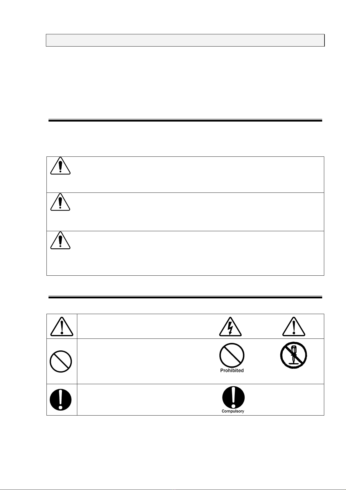
-2. Symbols of Instruction, Warning and Caution
The following display classifications describe details that should be followed.
Indicates attention (a matter that must be paid
attention fully)
Indicates prohibition (an action that must
not be taken)
Do not
disassemble
Indicates a compulsory action (an action
that must be taken)

BASIC SAFETY PRECAUTIONS
8
DANGER
Do not
disassemble
Do not take the Unit apart or do not remodel. Do not open the cover.
Imminent danger might occur resulting in death or serious injury. Repair, internal
adjustment, and inspection of the Unit should be performed by a qualified service
engineer. Ask the Company or its sales agent.
Do not use the Unit in an explosive are or fire-prohibited area etc.
Use of the Unit in such an area is liable to cause combustion or ignition.
A person who has a pacemaker on should not operate the Unit and also
should not enter the area where it is operating.
It may result in a fatal or serious accident.
WARNING
Stop operation if following unusual phenomena should occur.
Emitting fumes, or smelling.
Water or an unusual substance being stuck
Being dropped or being damaged
AC cable being damaged (e.g. core lines being exposed etc.)
Continuing to operate in the above status may result in a fire, electric shock, or injury. If
an unusual phenomenon occurs, turn off power supply immediately, pull AC plug out of
an outlet, and ask the Company or sales agent repair. As there is potential danger, any
user must not repair the product.
Turn off power supply of the Unit when setting or changing connection of
related equipment.
Failure to follow this notice may cause electric shock, injury, or malfunction.

BASIC SAFETY PRECAUTIONS
9
Use the Unit after understanding instructions in the Manual fully.
There may be danger causing a fatal or serious wound or emitting over-ristricted-value
electromagnetic noise in using the Unit. NOISE LABORATORY and its sales agents
shall have no liability against any accident resulting in injury or death, any damage to
equipment or any resultant damage thereof, which is caused by abuse or careless
handling of this unit.
Watch equipment while the Unit is operating.
If this instruction should not be followed, a third person or equipment related to the test
may be exposed to a danger.
Supply power within the indicated range.
Failure to follow this instruction may cause an electric shock or a fire. The attached AC
cord in the accessory is for AC100~120V.
Use proper connectors and cables and connect them securely.
Avoid using a damaged connector or cable. The misuse may cause an electric shock or
damage of equipment.
Insert AC plug securely to the end.
Insecure inserting generates heat and gathers dust. It may result in a fire or an electric
shock. Avoid using a multiple outlet extension plug for the same reason.
Install the Unit on a stable place.
If the Unit is installed on an unstable place, human body may be in danger due to drop
or overturn of the Unit.

BASIC SAFETY PRECAUTIONS
10
Do not put any substance into the Unit or its connectors.
If some metal or flammable things are put into the Unit through a connector or a vent, it
may result in a fire or an electric shock.
Do not install the Unit on the spot where quick operation of power key or
STOP key is difficult.
If the simulator is set up on such a spot, difficulty in taking action in emergency may
result in a fire or an electric shock.
Do not use the attached AC cable for any other purpose.
The misuse may result in a fire or an electric shock.
Do not damage AC cable.
A damaged AC cable may cause a fire or an electric shock.
For HV cable, be sure to take notice following points.
Do not work it.
Do not bend it forcibly.
Do not twist it.
Do not pull it.
Do not move it close to heat.
Do not put heavy things on it.

BASIC SAFETY PRECAUTIONS
11
CAUTION
If dewing occurs, fully dry up the Unit before using it.
Dews may cause an electric shock, a trouble, or a fire.
Use the Unit in proper environment.
Operating temperature range is 15~35ºC. Operating humidity range is 25~75%. If these
precautions are not followed, the unit may be broken or the prescribed performance may not
be warranted.
Clean up the AC plug periodically.
If dust gets damp between the AC plug and outlet, insulation capability deteriorates. It may
result in a fire. Pull the AC plug out from an outlet periodically and wipe it with a dry cloth.
When the body is dirty, wipe the body with a dry cloth.
Do not wipe the Unit and Probe with thinner, alcohol or other solvent. When the body is very
dirty, soak a cloth into neutral detergent, squeeze out the detergent from the cloth and wipe
the body with the cloth.

BASIC SAFETY PRECAUTIONS
12
Do not install the Unit on following places.
Setting up the Unit on wrong places as follows may result in a fire, an electric shock, or an
injury.
A very humid or dusty place
A hot place, e.g. a place exposed to direct rays of the sun, a place close to a
heater.
A place easy to bedew, e.g. a place close to a window.
Do not handle the AC plug with your hand wet.
The misuse may result in an electric shock or trouble.
Do not put any container containing water on the Unit.
If water is spilled or gets into the Unit, it may result in a fire or an electric shock.
Do not drop or shock the Unit excessively.
The misuse may cause trouble or damage.
Do not bump or rub the Unit against something hard.
The misuse may damage a surface of the Unit.
Do not put any heavy stuff or sit on the Unit.
The misuse may result in a dent on the body or damage of internal components.
13
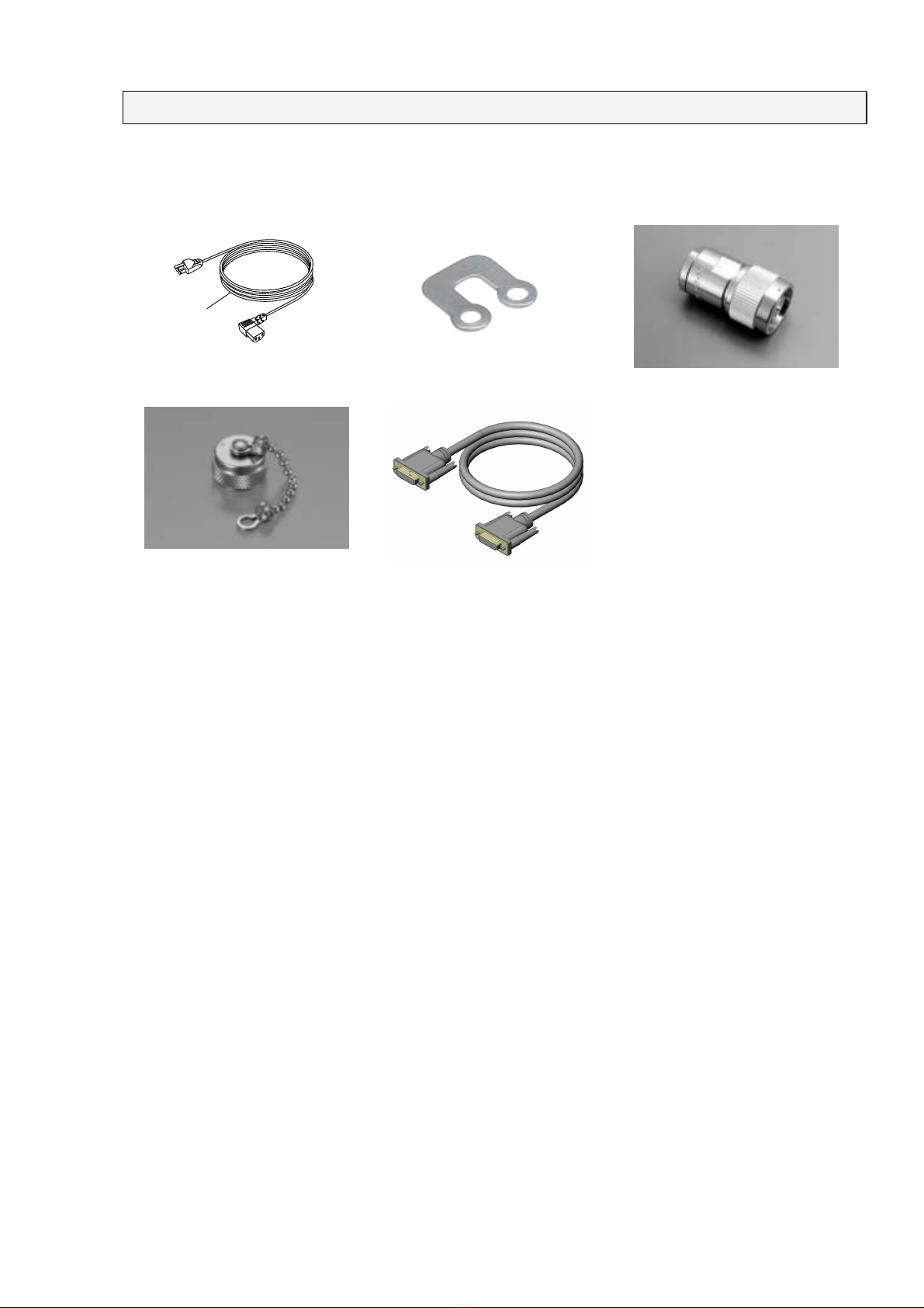
6. INCLUDEDACCESSORIES
The following accessories are included in the purchase package
A
B
C
D
E
A:AC cord······················································· 1
B:Short-bar (OSP-10 by Osada)·························· 2
C:N-connector 50-ohm terminated ······················· 1
D:BNC connector with a short-connection cap········ 1
E:D-Sub 9-pin connector cable (5m)····················· 1

14
7. CONTROLSANDINDICATORS
①:POWER key
The main POWER key for this device
②:INTERLOCK setting button
Provides a selection between SYNC (operational) and ASYNC (non-operational) for ⑧DOOR
terminals on the rear panel. When an open circuit is detected between ⑧DOOR terminals, the
SG output path is changed from SG IN-SG OUT to SG IN-50Ωwith SYNC INTERLOK setting.
③:DOOR status indicator
This indicator is lit red when the terminals on ⑧DOOR terminals are open.
④:RESET button
Resets the status of the internal ⑥SG connection relay on the rear panel to SG IN-SG OUT
from SG IN-50Ωconnection activated by ⑧DOOR terminals, ⑤EMERGENCY STOP button or
⑨EXT EMERGENCY port. When the lamp is lit, SG IN and SG OUT ports are internally
connected. When the lamp is off, SG IN port is connected to 50Ωport.
⑤:EMMERGENCY STOP button
The device is placed in the status shown below when this button is pressed.
・status change from SG IN to SG OUT to SG IN to 50Ωwith ⑥SG connection relay
・open interlocks (open circuit between the inner and outer conductors of the coaxial connectors
with ⑦AMP1 to 4
・disables ⑪EXT CNT connector
・short-circuiting for 7-8 pins on ⑫PC terminal
Releasing this button, turn the red button clockwise and pull it lightly.
①
POWER
key
④
RESET
button
②INTERLOCK
setting button
③DOOR
status indicator
⑤
EMERGENCY STOP button
15
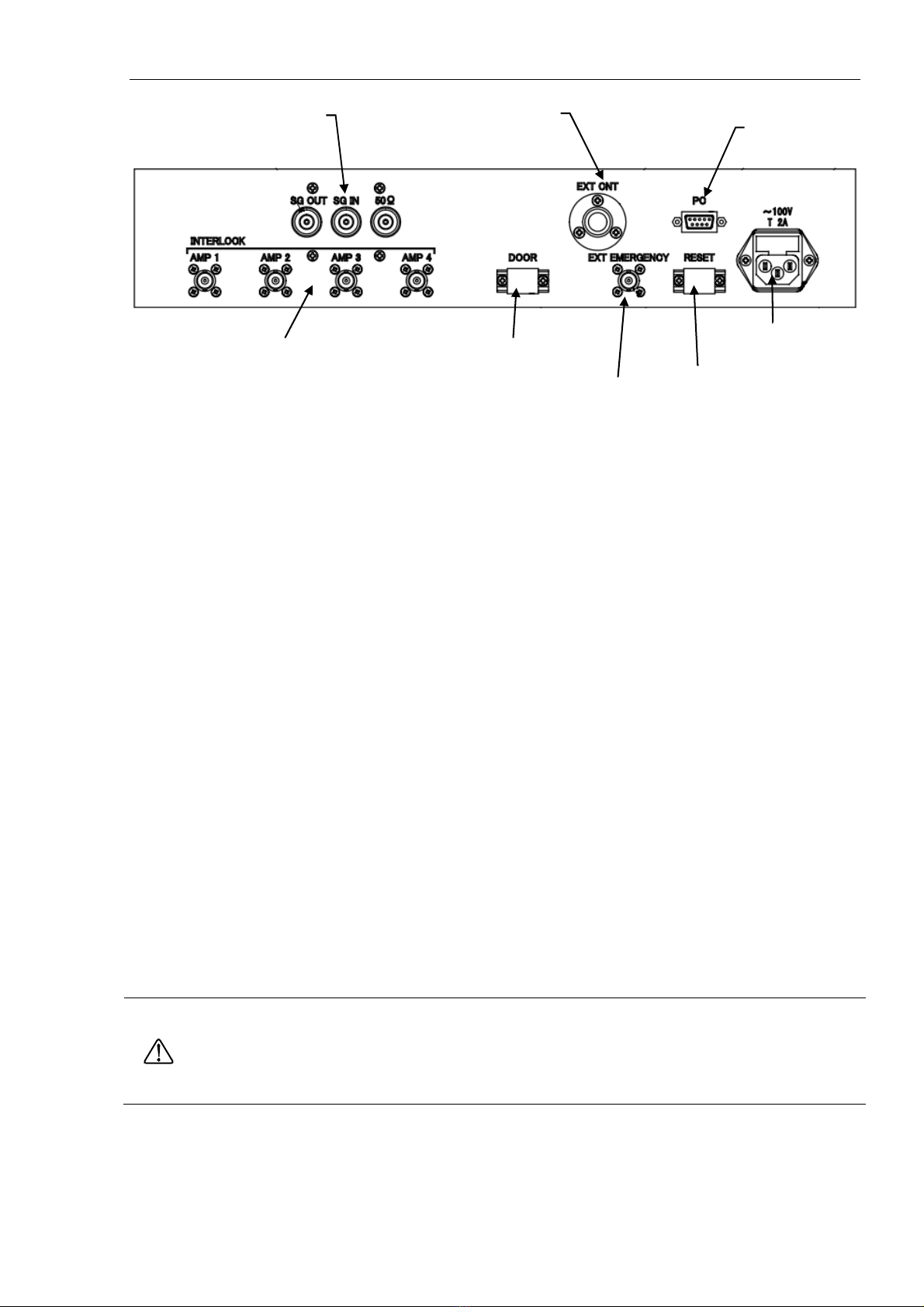
⑥:SG connection relay
The SG (signal generator) output is connected to SG IN, and SG OUT is connected to the
amplifier input and attach the supplied 50-ohm terminated N connector to 50Ωport. In normal
status, pressing ④RESET button establishes SG IN to SG OUT connection. Activating either of
⑧DOOR terminals, ⑤EMMERGENCY STOP button or ⑨EXT EMERGENCY interrupts the SG
output to the amplifier by internally switching the signal path to 50Ωcoaxial port.
⑦:AMP 1 to 4 INTERLOCK
Activating either by pressing ⑤EMMERGENCY STOP button or open-circuiting the inner and
outer conductors of ⑨EXT EMERGENCY coaxial connector sets open circuit conditions
between the inner and outer conductors of the coaxial connectors (AMP 1 to 4 coaxial ports). In
the normal status, the inner and outer conductors are short-circuited.
⑧:DOOR terminals
Open interlock is detected by opening the circuit between the two terminal. Connect the supplied
short-bar when the DOOR terminals are not used.
⑨:EXT EMERGENCY connector
An optional EMERGENCY BOX is connected. Open circuit between the inner and outer
conductors places the system in the same status as when the operator has pressed ⑤
EMERGENCY STOP. When this connector is not used, attach the supplied BNC connector with
a short-connection cap.
⑩:RESET terminals
Short-circuiting the both terminals (of RESET terminals) performs the same function as ④
RESET button on the front panel pressed. If you prefer to use ④RESET button on the front only,
remain the open circuit status for these terminals. When the operator does not use manual
RESET function (by ④RESET button on the front panel), connect the supplied short-bar to
RESET terminals.
With RESET terminals short-circuited with the short-bar, SG connection relay is set for SG IN to SG OUT
path immediately after the DOOR terminals are short-circuited or releasing
EMERGENCY STOP BUTTON.
When the signal generator is outputting signals, power output from the amplifier may be unexpectedly high.
Care should be taken to avoid this event.
⑪:EXT CNT
The connection port for optional remote control switch (13-00006A)
⑦AMP 1 to 4
INTERLOCK ⑨EXT EMERGENCY connector
⑧DOOR terminals
⑩RESET terminals
⑬AC inlet
⑥
SG
connection relay
⑪
EXT CNT
⑫PC connector

16
⑫:PC connector
The PC where NETS software has been installed is informed that the system is in Emergency
Stop status.
⑬:AC input
The AC power input for this device. Connect the supplied AC cord.

17
8. OPERATION
1.Make the required connections.
2.Turn on this device by pressing the POWER key to [I] side.
3.Select the desired mode for interlock setting of SYNC or ASYINC by using ②INTERLOCK
setting button.
4.Select SG IN to SG OUT path by pressing ④RESET button. The lamp on the left of ④
RESET button illuminates in green when SG IN to-SG OUT path has been selected.
When SG IN to SG OUT setting is not made by pressing ④RESET button (the lamp is off) ,
check the following:
* check to see that ⑤EMERGENCY STOP button has not been pressed.
⇒Turn ⑤EMERGENCY STOP button clockwise (or pull it lightly).
* check to see that EMERGENCY BOX (optional) has not been pressed or check short-circuit
between the inner and outer conductors of ⑨EXT EMERGENCY.
⇒Release EMERGENCY BOX button or attach the supplied BNC connector with a
short-connection cap
* Check to see the lamp of ③DOOR status indicator is off when SYNC mode has been selected
with the INTERLOCK setting button.
⇒Short-circuit the ⑧DOOR terminals
* Check to see that the remote control switch (optional) connected to EXT CNT has not been
pressed.
⇒Release the button .

18
9. WARRANTY
Services
The following terms are applicable to the services provided by the Company to maintain
and repair the Unit.
1. Scope
The Unit and accessories and options provided by the Company are covered under this
section.
2. Technical Service Fee
Any repairs provided by the Company during the warranty period will be free of charge in
accordance with the Limited Warranty. After expiration of the warranty period, actual cost for
the repair will be charged to the user.
3. Ownership of Defective Parts
All the defective parts replaced during the warranty period become the property of the
Company. For paid repairs, they also become the property of the Company unless otherwise
directed by the user.
4. Maximum Compensation
In the event the user incurs damage due to malfunction of the Unit arising solely from the
negligence and/or improper repair on the part of the Company, the Company will compensate
for the damage. The maximum compensation amount shall be limited to the amount paid by
the user at the time of purchase of the Unit. In no event, shall the company be liable or in any
way responsible for incidental or consequential damages such as loss of profit or third party’s
claims to the user.
5. Wrong Parts, Missing Parts and Damage
The company shall not be liable for loss of profit, business interruption, other incidental
damage, special loss, punitive damage or third party’s claims to the user directly or indirectly
arising from suspension of testing activities due to wrong parts, missing parts, or damage of
the Unit.
6.
Service Refusal
The company may not accept a repair order in the following cases:
More than 5 years have passed since the product discontinued
More than 8 years have passed after delivery
Required component for servicing already discontinued and no alternative is available.
Product changed, repaired or remodeled without obtaining a prior permission from the
Company.
Product severely damaged to the extent it has lost its original form
Table of contents
Other NoiseKen Laboratory Equipment manuals

NoiseKen
NoiseKen ISS-7610 User manual

NoiseKen
NoiseKen EPS-02Hv2 User manual

NoiseKen
NoiseKen ESS-801GL User manual

NoiseKen
NoiseKen LSS-6330 Series User manual

NoiseKen
NoiseKen SWCS-931SD User manual

NoiseKen
NoiseKen LSS-6330-B63 User manual

NoiseKen
NoiseKen FNS-AX4-A20 User manual

NoiseKen
NoiseKen IJ-02 User manual

NoiseKen
NoiseKen ESS-2000AX User manual

NoiseKen
NoiseKen LSS-6330-A20A User manual


