Estun TRIO Flex-X Nano User manual

USER MANUAL
Flex-X Nano
EtherCAT 64 AXIS MOTION COORDINATOR

Flex-X Nano
Document Version: 1.00
© 2023 All rights reserved.
1
About this Manual
Purpose
This manual provides the information required for the Selection, Wiring, Connection, Setup,
Operation and Functions of the Flex-X Nano Motion Coordinator.
Please read and understand this manual to ensure correct usage of the product.
Terms
Terms that may be used in this manual are defined as follows.
Term
Meaning
Axis
A software control that operates a Servo or Stepper Motor.
Drive
A Servo or Stepper Drive, which is used for controlling the Motor.
Servo System
A Servo Control System that includes a Motor, a Drive, a host controller (Motion
Coordinator) and peripheral devices.
WDOG ON
Setting the control word on EtherCAT to signal that the Drives may be Enabled.
WDOG OFF
Clear the control word to signal that the Drives must be Disabled.
Motion Perfect
The PC Tool for commissioning and programming the Trio product suite.
Pulse+Direction
An electronic output from the Motion Coordinator that produces one pulse per step
of the motor position, with a second output to signal the direction of motion.
Motion-iX
The motion-centric programming language, an extension of BASIC.
EtherCAT
Ethernet based fieldbus for synchronised control of slave devices in real-time.

Flex-X Nano
Document Version: 1.00
© 2023 All rights reserved.
2
Revision History
Date
Version
Revised Contents
6 Feb 2023
1.00
Initial release

Flex-X Nano
Document Version: 1.00
© 2023 All rights reserved.
3
All goods supplied by Trio are subject to Trio’s standard terms and conditions of sale.
This manual applies to systems based on the Motion Coordinator Flex-X Nano.
The material in this manual is subject to change without notice. Despite every effort, in a
manual of this scope errors and omissions may occur. Therefore, Trio Motion Technology Ltd.
cannot be held responsible for any malfunctions or loss of data as a result.
Copyright (C) 2023 Trio Motion Technology Ltd.
All Rights Reserved
UK
Trio Motion Technology Ltd.
Phone: +44 (0)1684 292333
USA
Trio Motion Technology LLC.
Phone: + 1 724 472 4100
CHINA
Trio Shanghai
Tel: +86 21 587 976 59
INDIA
Trio India
Phone: +91 827 506 5446

Flex-X Nano
Document Version: 1.00
© 2023 All rights reserved.
4
Safety Warning
During the installation or use of a control system, users of Trio products must ensure there is
no possibility of injury to any person, or damage to machinery.
Control systems, especially during installation, can malfunction or behave unexpectedly.
Users must ensure that in all cases of normal operation, controller malfunction, or
unexpected behaviour, the safety of operators, programmers or any other person is totally
ensured.

Flex-X Nano
Document Version: 1.00
© 2023 All rights reserved.
5
Contents
Revision History ............................................................................................2
User Manual Flex-X Nano .................................................................................7
Overview .................................................................................................7
Programming.............................................................................................7
I/O Capability............................................................................................8
Communications.........................................................................................8
IP Address reset .........................................................................................8
Removable storage......................................................................................8
Axis positioning functions ..............................................................................8
LED indicators ...........................................................................................9
Connections to the Flex-X Nano.......................................................................9
Registration ......................................................................................... 10
Expanding the system ................................................................................ 10
EBUS loading ........................................................................................ 11
Support Software...................................................................................... 12
Motion Perfect version 5 .......................................................................... 13
Software functions .................................................................................... 14
EtherCAT network..................................................................................... 15
Example 1 ........................................................................................... 15
Example 2 ........................................................................................... 15
Example 3 ........................................................................................... 16
Adding axes ............................................................................................ 16
Firmware recovery .................................................................................... 17
Dimensions ............................................................................................. 18
Mounting................................................................................................ 18
Specifications .......................................................................................... 19
Electromagnetic Compatibility...................................................................... 21
Intended conditions of use ........................................................................ 21
EMC Considerations ................................................................................ 21
Product specific requirements ................................................................... 21
Recommended Installation........................................................................ 23

Flex-X Nano
Document Version: 1.00
© 2023 All rights reserved.
6
Surge Protection.................................................................................... 23
Surge protection device ........................................................................... 24
Cable Shields ........................................................................................ 25

Flex-X Nano
Document Version: 1.00
© 2023 All rights reserved.
7
User Manual Flex-X Nano
Overview
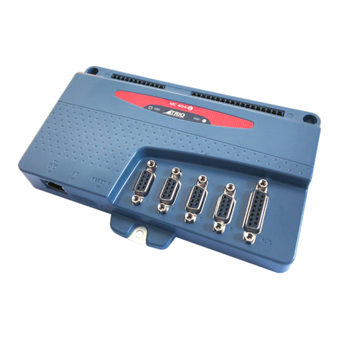
The Motion Coordinator Flex-X Nano is based on Trio’s
high-performance ARM Cortex-A55 double-precision
technology and provides up to 64 axes of coordinated
motion using the EtherCAT bus system to connect to Drives
and I/O. The Flex-X Nano is a form, fit and function
compatible replacement for the Flex-6 Nano. It is housed
in a rugged plastic case with integrated earth chassis and
incorporates two screened RJ45 Ethernet ports, a 24V dc
power connector and micro SD card slot. The upper RJ45
connector is for a standard Ethernet connection to the PC
for programming and the lower connector is for the
EtherCAT Fieldbus. Filtered power supplies (DC/DC
converters) are included so that it can be powered from
the 24V d.c. logic supply present in most industrial
cabinets.
It is designed to be configured and programmed for the
application using a PC running Trio’s Motion Perfect
application software, and then may be set to run
“standalone” if an external computer is not required for
the final system. Programs and data are stored directly to
FLASH memory, thus eliminating the need for battery
backed storage.
The Multi-tasking version of Motion-iX for the Flex-X Nano
allows up to 22 Motion-iX programs to be run
simultaneously on the controller using pre-emptive multi-
tasking. In addition, the operating system software includes the IEC 61131-3 standard run-
time environment that has access to the full library of motion functions.
Programming
The Multi-tasking ability of the Flex-X Nano allows parts of a complex application to be
developed, tested and run independently, although the tasks can share data and motion
control hardware. The 22 available processes can be used for Motion-iX or IEC 61131-3
programs, or a combination of both can be run at the same time, thus allowing the
programmer to select the best features of each.
The Flex-X Nano is fully compatible with Trio’s Robot Programming System (RPS) and the
user can decide to write programs using the powerful Motion iX functions or the RPS motion
suit which is tailored to SCARA and other industrial robot systems. Both RPS and Motion iX /
IEC programs may be run on the same Motion Coordinator thus allowing the powerful Flex-X
Nano to control many auxiliary motors as well as the robot arm(s).
Flex-X Nano
Document Version: 1.00
© 2023 All rights reserved.
8
I/O Capability
The Flex-X Nano has the ability to add up to 16 EtherCAT FLexslice input / output modules
using the EBUS connector on the side. Modules are supported mechanically by a positive
latch system that allows rapid assembly that results in a robust final assembly ready for
clipping on the DIN rail. These may be used for system interaction or may be defined to be
used by the controller for end of travel limits, soft registration, datuming and feedhold
functions if required. The Flex-X Nano can have up to 1024 external Input and Output
channels connected using a combination of the local EBUS and remote EtherCAT IO via the
P366 bus coupler module.
Communications
A 100 base-T Ethernet port is fitted as standard and this is the primary communications
connection to the Flex-X Nano. Protocols supported include Telnet (Client and Server),
Modbus TCP (Client and Server), Ethernet IP (Slave), Profinet (Slave) and the TrioPCMotion
DLL/ActiveX channel.
IP Address reset
To reset the IP _ ADDRESS, IP _ GATEWAY and IP _ NETMASK to their default values press the
IP reset button, located under the upper ventilation slots, and power cycle the controller
while keeping the button pressed.
The factory default IP
address is 192.168.0.250.
This can be changed using
the ETHERNET or IP_ADDRESS
commands via Motion
Perfect.
IP_ADDRESS and other settings may also be changed by adding the commands to a file called
TRIOINIT.BAS on a micro-SD card and powering up the Flex-X Nano with the card inserted in
the SD slot.
Removable storage
The Flex-X Nano has a micro-SD Card slot which allows a simple
means of transferring programs, firmware and data without a PC
connection. Offering the OEM easy machine replication and servicing.
The memory slot is compatible with a wide range of micro-SD cards
up to 32 GBytes using the FAT32 compatible file system.
Axis positioning functions
The motion control generation software receives instructions to move an axis or axes from
the Motion-iX or IEC 61131-3 language which is running concurrently on the same processor.
The motion generation software provides control during operation to ensure smooth,
coordinated movements with the velocity profiled as specified by the controlling program.

Flex-X Nano
Document Version: 1.00
© 2023 All rights reserved.
9
Linear interpolation may be performed on groups of axes, and circular, helical or spherical
interpolation in any two/three orthogonal axes. Each axis may run independently, or they
may be linked using interpolation, variable electronic gearboxes and kinematic transform.
Consecutive movements may be merged to produce continuous path motion and the user
may program the motion using programmable units of measurement (e.g. mm, inches, revs
etc.). The module may also be programmed to control only the axis speed. The positioner
checks the status of end of travel limit switches which can be used to cancel moves in
progress and alter program execution.
LED indicators
2 LEDs show the status of the power and the enable circuit.
The enable circuit drives the watchdog relay and activates the
pulse output signals.
Red LED ON shows that the WDOG is off and the axes are
disabled. When the red LED is OFF, the axes are enabled and
ready to move. A flashing red LED indicates that one or more
axes are in error.
RN is the run status of the EtherCAT network and LA show the
EtherCAT network activity.
RN LED
EtherCAT State
OFF
Initial
Uniform flash
Pre-Operational
Brief flash
Safe-Operational
ON
Operational
Connections to the Flex-X Nano
24V power supply
The Flex-X Nano requires a Class 2 transformer
or power source within the range 18..29V d.c.
Current consumption is 350mA when a full set
of 16 Flexslice I/O modules are connected to
the EBUS connector.
A 2 part connector is provided which has push-
fit cable entry ports with spring clamp and
positive push to release operation.
Recommended wire cross section 0.2 .. 1 mm2/ 28 AWG .. 16 AWG.

Flex-X Nano
Document Version: 1.00
© 2023 All rights reserved.
10
Ethernet port connection (Upper socket)
RJ45 socket 10/100 base-T
The Ethernet port is the default connection between the Motion Coordinator
and the host PC running the Motion Perfect development application.
In addition, the Ethernet port will provide connection using common Ethernet industrial
protocols such as Modbus, CIP and Profinet.
EtherCAT port connection (Lower socket)
RJ45 socket 100 base-T
The Flex-X Nano acts as an EtherCAT master. EtherCAT drives and I/O devices
are normally connected in a chain.
Ethernet standard pin assignment:
Pin
Signal
Description
1
TD+
Transmission data +
2
TD-
Transmission data -
3
RD+
Receive data +
6
RD-
Receive data -
Straight through (patch) or cross-over cables can be used between EtherCAT devices.
Minimum cable specification: CAT 5e shielded SF/UTP cable is recommended.
Registration
Flex-X Nano requires servo and stepper drives connected by EtherCAT to support the CiA402
Touch Probe system. With the touch probe objects included in the cyclic data PDO, the
Motion Coordinator programs can use the REGIST command to access the registration inputs
and functions in the remote drives. Precise position capture can then be done to enable
operation of many machine types which include printing, cutting and scanning machines.
Expanding the system
The Flexslice system makes available a selection of digital and analogue I/O terminals as
well as motion modules with analogue servo and pulse + direction outputs designed for
precise positioning of stepper and servo motors via suitable drive technology. The digital
I/O modules have high-speed functionality and can sample on each EtherCAT cycle. In
addition, analogue modules and axis modules may be fitted to make a superbly tailored
system that can be placed remotely from the master if needed.

Flex-X Nano
Document Version: 1.00
© 2023 All rights reserved.
11
All Flexslice modules support automatic
addressing with the master able to
automatically detect and configure the
modules on startup. The Flex-X Nano
supports up to 16 input/output modules
which have a positive mechanical lock and
bus connector, making a reliable “back-
bone” style connection (EBUS). The complete
assembly can be DIN rail mounted.
EBUS loading
Internal power for each Flexslice module is provided from the P660 Flex-X Nano. The
maximum current available can supply up to 16 simple digital input / output modules. When
other modules are attached such as the analogue or axis modules, extra power is needed for
the internal microcontroller so the number of modules will therefore need to be reduced.
Description
Thermocouple RTD Load Cell 16 Output PNP 16 Input PNP
Analogue 2
Servo Axis
Flex 3-Axis 16 Output NPN 16 Input NPN
8 Analogue
Outputs
8 Analogue
Inputs
32 Output NPN 32 Input NPN
Flexslice P367 P368 P369 P371 P372 P374 P375 P376 P377 P378 P379 P386 P387
Unit Load 1.25 1.25 1.25 1 1 2.5 2 1 1 4 1.25 1 1
Qty 2 2 2 1
Total Load 12.00
(Max = 16)
EBUS load Okay
Instructions
1) Enter the quantity of each Flexslice in the system in the light
green "Qty" boxes.
2) The total load will automatically update.
3) If the maximum load is exceeded a warning will be given.
EBUS load calculator
The table above shows the load weighting for a range of Flexslice modules. Multiply Unit
Load by the quantity of modules of that type. The sum of all modules thus weighted must
not exceed 16.
The EBUS load calculator may be downloaded from Trio’s website.

Flex-X Nano
Document Version: 1.00
© 2023 All rights reserved.
12
Support Software
Motion Perfect version 5 or later is required for configuration, programming and system
debug. A PC running Microsoft Windows (Windows 10 or later recommended) is required.
Download Motion Perfect from www.triomotion.com and install on the PC.
Connection is via the Ethernet
port. Ensure that the PC has a
valid Ethernet Address. For single
point-to-point connection, a fixed
IP address must be set in the PC.
Go to Settings, Network and
Internet then open Change
Adapter Settings. Open the
Ethernet port.
Click the Properties button and
then select Internet Protocol
Version 4 (TCP/IPv4).
Click Properties and select Use the following IP
address. Set an IP address in the same subnet as
the Flex-X Nano. Usually this will be
192.168.0.xxx.
Click OK and close the Ethernet setup dialogues.

Flex-X Nano
Document Version: 1.00
© 2023 All rights reserved.
13
Motion Perfect version 5
Launch Motion Perfect and select the IP address of the Flex-X Nano. By default this will be
192.168.0.250. Click the Apply and Connect button.
If the IP Address of the Flex-X Nano is not known, then reset it by holding the IP Reset
button, located under the ventilation slots on the top face, while powering up the Flex-X
Nano. This will reset the IP_ADDRESS to 192.168.0.250.
Motion Perfect in Synchronised
connection mode.

Flex-X Nano
Document Version: 1.00
© 2023 All rights reserved.
14
Software functions
The Flex-X Nano contains a stand-alone operating system which includes a rich set of built-in
motion functions accessible from both the interpreted Motion iX text language and the IEC-
61131-3 standard PLC language. A short summary of the main functions is shown in the table
below.
Function
name
(Keyword)
Description
Notes
MOVE
Incremental move. One axis or multiple axes move at the
programmed speed and acceleration.
SPEED sets vector
speed.
MOVEABS
Absolute position move. Move one axis or multiple axes to
position(s) referenced with respect to the zero (home) position.
MOVECIRC
Moves 2 orthogonal axes in such a way as to produce a circular
arc at the tool point.
MHELICAL
Moves 2 orthogonal axes in such a way as to produce a circular
arc at the tool point with a simultaneous linear move on a third
axis.
MSPHERICAL
Moves 3 orthogonal axes along a spherical path.
MOVEABSSEQ
Allows a sequence of movements to be run from a pre-loaded
table of position values. The moves can be automatically merged
together using fillets. (circular arcs)
MOVESP
Same as MOVE with addition of speed profile control for cutting
and machining operations.
CORNER CONTROL
enabled
MOVEABSSP
Same as MOVEABS with addition of speed profile control for
cutting and machining operations.
MOVECIRCSP
Same as MOVECIRC with addition of speed profile control for
cutting and machining operations.
MHELICALSP
Same as MHELICAL with addition of speed profile control for
cutting and machining operations.
MSPHERICALSP
Same as MSPHERICAL with addition of speed profile control for
cutting and machining operations.
CONNECT
Link 2 axes together so that one axis follows the other with a
defined gear ratio.
MOVELINK
Link 2 axes together temporarily with a defined ramp up and
ramp down on the following axis.
Linear or S-curve
acceleration
profile
FLEXLINK
Link an axis to a driving axis with varying ratio over a base
distance and programmable excitation distance.
CAMBOX
User defined constantly changing ratio between the axis and its
driving axis. (Cam shape supplied by user program)
MOVEPICK
Pre-defined pick and place profile. User defined overlap and
withdraw distances.

Flex-X Nano
Document Version: 1.00
© 2023 All rights reserved.
15
EtherCAT network
EtherCAT slave devices may be added to make a network. Device addresses will default to
their position on the network with the local I/O being located first ahead of any external
devices. Addresses can be altered by settings in the slaves or in the master if required.
Example 1
Example 2

Flex-X Nano
Document Version: 1.00
© 2023 All rights reserved.
16
Example 3
Adding axes
Depending on the version ordered, the Flex-X Nano will be able to connect and start a
certain number of axes (drives).
Product code
Max. axes
Product code
Max. axes
P660
2
P661
4
P662
8
P663
16
P664
32
P665
64 [1]
It is possible to extend the number of axes by purchasing a
Feature Enable Code (FEC) from the original supplier of the
Flex-X Nano. The order code for axis extension is P912.
Each P912 will provide a FEC to double the number of axes
that can be initialised and run.
FECs are added via Motion Perfect.
FEC0 to FEC4 will enable 2x axes for each code.
[1] Special use only. Contact Trio.

Flex-X Nano
Document Version: 1.00
© 2023 All rights reserved.
17
Firmware recovery
In the unlikely event that the Motion Coordinator firmware becomes corrupted, and the
processor will not start the Ethernet port and allow communication, the Flex-X Nano, has a
firmware recovery mode. The recovery is automatic and forces the processor to run a
protected boot area of the memory that is dedicated to restoring the full operating system
from a SD card.
The following equipment is needed to complete the Firmware Recovery:
•Micro SD card formatted to FAT32. Max size 32GB.
•Firmware file for the Flex-X Nano, downloaded from the Trio Website.
Rename the firmware file to r_660.out and copy it to the root folder on the micro-SD card.
With the power off, insert the micro-SD card into the slot and then turn on the power. The
red LED will flash during the firmware loading process. When the Red LED becomes steady it
will be possible to re-connect to the Motion Coordinator via Ethernet. If the IP address is
not known, then power off, hold the IP reset button and power on again to set the default IP
address 192.168.0.250, subnet mask 255.255.255.0 and default gateway 192.168.0.225.

Flex-X Nano
Document Version: 1.00
© 2023 All rights reserved.
18
Dimensions
Mounting
The Flex-X Nano has a standard DIN rail mount with over-centre clip operated by a lever on
the lower face. It must be installed on an unpainted metal plate with DIN rail which is
connected to earth.
Ventilation: When the Flex-X Nano is mounted in an enclosed cabinet, there must be an
adequate volume of circulating air to maintain the environmental temperature within the
operating temperature range. If clearance is allowed for cable connections, there is no
further limit on spacing next to other components that do not emit heat.
Place below heat sources such as drives and power supplies.

Flex-X Nano
Document Version: 1.00
© 2023 All rights reserved.
19
Specifications
Specification table
Size
147 mm x 107 mm x 17 mm (HxWxD)
Weight
160g
Operating Temp.
0 - 45 degrees C
EMC (CE)
EMISSIONS –EN IEC 61000-6-4 : 2019
IMMUNITY –EN IEC 61000-6-2 : 2019
EMC (UKCA)
EMISSIONS –BS EN IEC 61000-6-4 : 2019
IMMUNITY –BS EN IEC 61000-6-2 : 2019
Control Inputs
Via I/O expansion
Forward Limit
Reverse Limit
Datum Input
Feedhold Input
Communication Ports
Ethernet : 10/100 Base-T multiple port connection.
EtherCAT : 100 Base-T cyclic at SERVO_PERIOD rate.
EBUS : Local EtherCAT bus for Flexslice Module expansion.
Position Resolution
64 bit internal position registers
Speed Resolution
32 bits. Speed may be changed at any time
Moves may be merged
Servo Cycle
125μs minimum
1ms default
4ms max
Programming
Multi-tasking Motion iX system
IEC 61131-3 programming system.
Maximum 22 user processes.
Interpolation modes
Linear, circular, helical, spherical, CAM Profiles, speed control,
software gearbox and linked motion.
Special profiles for Pick and Place, Dispensing and CNC.
Processor
ARM Cortex-A55 dual core, 1.2GHz max clock frequency.
Table of contents
Other Estun Controllers manuals

Estun
Estun E21S User manual

Estun
Estun TRIO Flex-6 Nano User manual

Estun
Estun Trio MC404-Z User manual

Estun
Estun E200P User manual

Estun
Estun E21 User manual

Estun
Estun S1E Series User manual

Estun
Estun E21 User manual

Estun
Estun E200 User guide

Estun
Estun E21 User manual

Estun
Estun EP1000 PLC Owner's manual
Popular Controllers manuals by other brands

Grundfos
Grundfos PM TWIN Installation and operating instructions

Savant
Savant SmartControl 12 Deployment guide

WEG
WEG AVR-A-OPT-16 Installation, operation and maintenance manual

Rosemount
Rosemount 54E instruction manual

Inter-m
Inter-m IMS-9000 operating manual

Biegler
Biegler autopress e Instructions for use