ETC Response Mk2 One-Port Quick start guide

ETC Service Note
Power Control Processor Mk2 Replacement
Corporate Headquarters nMiddleton, WI, USA |+1 608 831 4116
Global Offices nLondon, UK |Rome, IT |Holzkirchen, DE |Paris, FR |Hong Kong |Dubai, UAE |Singapore
New York, NY |Orlando, FL |Los Angeles, CA |Austin, TX
Web etcconnect.com |Support support.etcconnect.com |Contact etcconnect.com/contactETC
© 2023 Electronic Theatre Controls, Inc. |Trademark and patent info: etcconnect.com/ip
Product information and specifications subject to change. ETCintends this document to be provided in its entirety.
7123M3310 Rev A Released 2023-02
Overview
Note:
The Power Control Processor Mk2 Replacement Kit is for use with panels where a
Power Control Processor Mk2 is already installed.
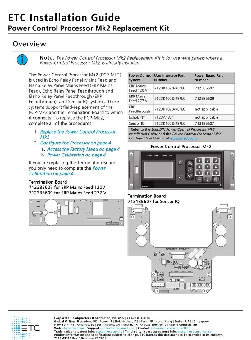
The Power Control Processor Mk2 (PCP-Mk2)
is used in Echo Relay Panel Mains Feed and
Elaho Relay Panel Mains Feed (ERP Mains
Feed), Echo Relay Panel Feedthrough and
Elaho Relay Panel Feedthrough (ERP
Feedthrough), and Sensor IQ systems. These
systems support field-replacement of the
PCP-Mk2 and the Termination Board to which
it connects. To replace the PCP-Mk2,
complete all of the procedures:
1.
Replace the Power Control Processor
Mk2
2.
Configure the Processor on page3
a.
Access the Factory Menu on page3
b.
Power Calibration on page4
If you are replacing the Termination Board,
you only need to complete the
Power
Calibration on page4
.
Termination Board
7123B5607 for ERP Mains Feed 120V
7123B5609 for ERPMains Feed 277V
Power Control
System
User Interface Part
Number
Power Board Part
Number
ERP Mains
Feed 120V 7123K1028-REPLC 7123B5607
ERP Mains
Feed 277V 7123K1028-REPLC 7123B5609
ERP
Feedthrough 7123K1028-REPLC not applicable
SensorIQ 7123K1028-REPLC 7131B5607
Power Control Processor Mk2
Termination Board
7131B5607 for Sensor IQ

ETC Service Note
Power Control Processor Mk2 Replacement
Power Control Processor Mk2 Replacement Page 2 of 4 ETC
WARNING: RISK OF DEATH BY ELECTRIC SHOCK! Failure to disconnect all
power to the panel before working inside could result in serious injury or death.
AVERTISSEMENT : RISQUE D'ELECTROCUTION! Travailler à l’intérieur du
panneau sans avoir déconnecté le courant peut entrainer des blessures graves,
voire mortelles.
De-energize main feed to the panel and follow appropriate Lockout/Tagout
procedures as mandated by NFPA 70E. It is important to note that electrical
equipment such as relay panels can present an arc flash hazard if improperly
serviced. This is due to the high amounts of short-circuit current available on the
electrical supply to this equipment. Any work must comply with OSHA Safe
Working Practices.
Included in the Replacement Kit
Description ETCPart Number Quantity Notes
PCP-Mk2 user
interface 7123A2216-CFG 1
Retainer clip HW7519 1 for the user interface ribbon cable
Nylon spacer HW9444 2 for moving a RideThru Option Card from an old user interface to a new user
interface in ERP Mains Feed or ERP Feedthrough, if necessary
Required Tools
• Phillips screwdriver
Replace the Power Control Processor Mk2
Disconnect the Wiring from the Old User Interface
1. Disconnect the network patch cable and six-color power wiring harness from the old user
interface.
2. Remove the retainer clip securing the gray ribbon cable to the header on the old user
interface and gently pull the ribbon cable from the header.
• You may discard the retainer clip from the old user interface. A new retainer clip
(HW7519) is provided in the kit.
3. If your ERPMains Feed or ERPFeedthrough panel has a RideThru Option Card installed
complete the steps at
Move a RideThru Option Card - ERP Mains Feed or ERPFeedthrough on
page3
.
• If you have a Sensor IQ panel or if you do not have a RideThru Option Card, continue
with
Connect the Wiring to the PCP-Mk2 on page3
.

ETC Service Note
Power Control Processor Mk2 Replacement
Power Control Processor Mk2 Replacement Page 3 of 4 ETC
Move a RideThru Option Card - ERP Mains Feed or
ERPFeedthrough
If your ERP Mains Feed or ERP-Feedthrough panel has a RideThru Option Card, follow the
instructions below to move it to the new PCP-Mk2.
1. Disconnect the red-and-black harness from the old user interface's two-pin "ride thru"
header.
2. Remove the three screws securing the RideThru Option Card to the old user interface.
• Set the three screws aside for reinstallation.
• Keep any spacers that were installed with these screws. You will need a total of three
spacers to install the RideThru Option Card on the new user interface. Two spare spacers
(ETCpart number HW9444) are included in the Power Control Processor Mk2
Replacement Kit.
3. Secure the RideThru Option card to the new user interface with the three screws you
removed above, placing one spacer on each screw between the user interface and the
RideThru Option Card bracket.
4. Connect the free end of the red-and-black harness on the RideThru Option Card to the two-
pin "ride thru" header on the new user interface.
Connect the Wiring to the PCP-Mk2
1. Install the gray ribbon cable to the header on the new user interface and secure it with the
retainer clip (included, ETCpart number HW7519).
2. Install the free end of six-color power wiring harness to the new user interface.
3. Connect the network patch cable to the new user interface.
Configure the Processor
Note:
After configuring the PCP-Mk2 via the UI, save the configuration file and reboot
the PCP-Mk2.
Access the Factory Menu
Manufacturing Tests
Run All
Rack Class Test
Calibration
Button Test
LED Test
LCD Test
USB Test
1. Hold down the [1] key while rebooting the processor until the
Manufacturing Tests menu appears.
• To reboot the processor: Press the reset switch at the bottom
right with a non-sharp, pointed object (e.g. a pen).
2. Release the [1] key.
• You will now have access to the Manufacturing Tests menu.
3. Use [Up] () and [Down] () to navigate to the Rack Class Test menu.
4. Press [Enter] (ü) to confirm the selection.
5. Use [Up] () and [Down] () to select the appropriate rack type and press enter to commit the
selection.
•ERP - for US ERP racks
•ERPCE - for CE EchoDIN systems
•Sensor IQ - for Sensor IQ Intelligent Breaker Panels
•ERP-FT - for ERP-FT racks
6. Press [Back] ( ) two times to exit the factory menu.

ETC Service Note
Power Control Processor Mk2 Replacement
Power Control Processor Mk2 Replacement Page 4 of 4 ETC
Power Calibration
Note:
Power supply calibration only applies to ERP Mains Feed and Sensor IQ panels. If
the power supply is not correctly calibrated, the unit will display BACK UP POWER ACTIVE
on the screen, or will display incorrect voltage values.
To calibrate a panel, you will need a measurement of the incoming voltage. Voltage measurement
should only be undertaken by trained personnel wearing appropriate protective equipment.
1. Access the Factory Menu. See
Access the Factory Menu on the previous page
.
2. Use [Up] () and [Down] () to navigate to Calibration.
3. Use the numeric key pad to enter the measured voltage, multiplied by 100.
• For example, if your measured voltage was 120.26V, you would enter 12026.
4. Press [Back] ( ) to exit the Calibration screen.
5. Press [Back] ( ) a second time to boot to the main software.
Save Configuration
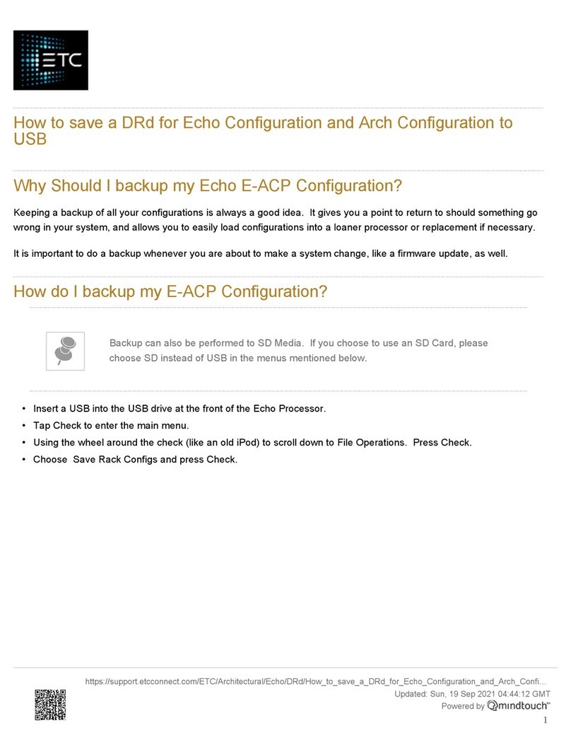
Saving a panel configuration creates a file for storage to the root directory of a connected
USBstorage device.
1. Insert a USBstorage device in the USB port on the left side of the front of the user interface.
2. Navigate to File Operations.
3. Press [Enter] (ü) to select Save Configuration.
4. The Save Configuration screen displays and the default "Filename:Echo1" is selected. You
can save your file under a name between Echo1 and Echo16.
5. To select a different filename, press [Enter] (ü). The selection will focus on "Echo#".
6. Use [Up] () and [Down] () to scroll through the list. Press [Enter] (ü) to make the selection.
7. Scroll to Save to USB key and press [Enter] (ü). The dialog will display "Saving to USB". The
file will always be saved to the root directory of the USBdevice.
Reboot the Processor
Reboot the PCP-Mk2.
Compliance
For complete product documentation, including compliance documentation, visit
etcconnect.com/products.
Other manuals for Response Mk2 One-Port
5
This manual suits for next models
1
Other ETC Computer Hardware manuals