manuals.online logo
Brands
  1. Home
  2. •
  3. Brands
  4. •
  5. Leviton
  6. •
  7. Security Sensor
  8. •
  9. Leviton IPSD6 User manual

Leviton IPSD6 User manual

Sensor is located in electrical box with LINE
connection:
WARNINGS AND CAUTIONS:
• TO AVOID FIRE, SHOCK, OR DEATH; TURN OFF POWER AT CIRCUIT BREAKER OR FUSE AND TEST THAT THE POWER IS OFF BEFORE WIRING!
• Tobeinstalledand/orusedinaccordancewithelectricalcodesandregulations.
• Toavoidoverheatingandpossibledamagetothisdeviceandotherequipment,DO NOTinstalltocontrolareceptacle,amotor,oratransformer-operatedappliance
otherthanapplicablespeciedlightingload:Incandescent,LEDorCFL.
• Whenusingina3-wayapplicationuseonesensorandonestandard3-wayswitch.Cannotbeusedwithanothersensor,orina4-wayapplication.
WARNINGS AND CAUTIONS:
• Ifyouarenotsureaboutanypartoftheseinstructions,consultanelectrician.
•Cleanoutersurfacegentlywithdampclothonly.DO NOT usesoapsorcleaningliquids.
•Nouserserviceablecomponents.DO NOT attempttoserviceorrepair.
• UsethisdeviceWITH COPPER OR COPPER CLAD WIRE ONLY.
RESET
RESET
TEST
TEST
1 2
0 3
Push down tabs per
diagram, one at a time and
rotate forward to release
1 2
0 3
1 2
0 3
1 2
0 3
Attach new face by inserting
bottom hinge tabs, then pivot
and snap the color kit to attach
Tools needed to install your Device
Slotted/PhillipsScrewdriver ElectricalTape Pliers
Pencil   Cutters  Ruler
Changing the color of your device:
Yourdevicemayincludecoloroptions.Tochangecoloroftheface
proceedasfollows:
√
INSTALLING YOUR DEVICE
NOTE: UsecheckboxeswhenStepsarecompleted.
IMPORTANT:For3-wayapplications,notethatoneofthescrew
terminalsfromtheoldswitchbeingremovedwillusuallybea
differentcolor(Black)orlabeledCommon.Tagthatwirewith
electricaltapeandidentifyasthecommon(LineorLoad)inboththe
sensorwallboxandremotewallbox.
2
4
1
5
3
3-Way
1. LineorLoad (See important
instruction below)
2. Neutral
3. Ground
4. FirstTraveler–notecolor
5. SecondTraveler–notecolor
2
4
3
1
Single-Pole
1. Line(Hot)
2. Neutral
3. Ground
4. Load
Step 2 Identifying your wiring application
(most common):
NOTE:Ifthewiringinthewallboxdoesnotresembleany
ofthesecongurations,consultanelectrician.
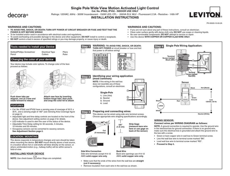
WIRING SENSOR:
Connect wires per WIRING DIAGRAM as follows:
• GreenorbarecopperwireinwallboxtoGreenterminalscrew.
• LineHotwallboxwiretoterminalscrewmarked"BK".
• Loadwallboxwiretoterminalscrewmarked"RD".
• Terminalscrewmarked"3-way"shouldhaveRedinsulationlabel
afxed.
NOTE: Ifinsulatinglabelisnotafxedtoterminalscrewmarked
"3-way",useelectricaltapetocover.
• ProceedtoStep5.
Use Terminal for 3-Way
Applications Only.
For Single Pole Applications,
Do Not Remove This Label.
Hot (Black)
Neutral (White)
Red Black
Black
White
LOAD
Line
120VAC, 60 Hz
Sensor
Green
Ground
3-Way
(Brass
Screw)
BK
RD
3-Way
Terminal
Screw marked
Red (RD)
2
Terminal
Screw marked
Black (BK)
Brass
Terminal Screw
Marked 3-Way
Terminal Label:
Use Terminal for 3-Way Applications Only.
For Single Pole Applications, Do Not Remove This Label.
4
1
3
Step 4 Single Pole Wiring Application:
Single Pole and 3-Way Wide View Motion Activated Light Control & Dimmer
Cat. No. IPSD6, IPVD6 - INDOOR USE ONLY
Ratings:120VAC,60Hz600WIncandescent&150WDimmableLED&CFL
INSTALLATION INSTRUCTIONS
PK-93918-10-00-2B
FEATURES
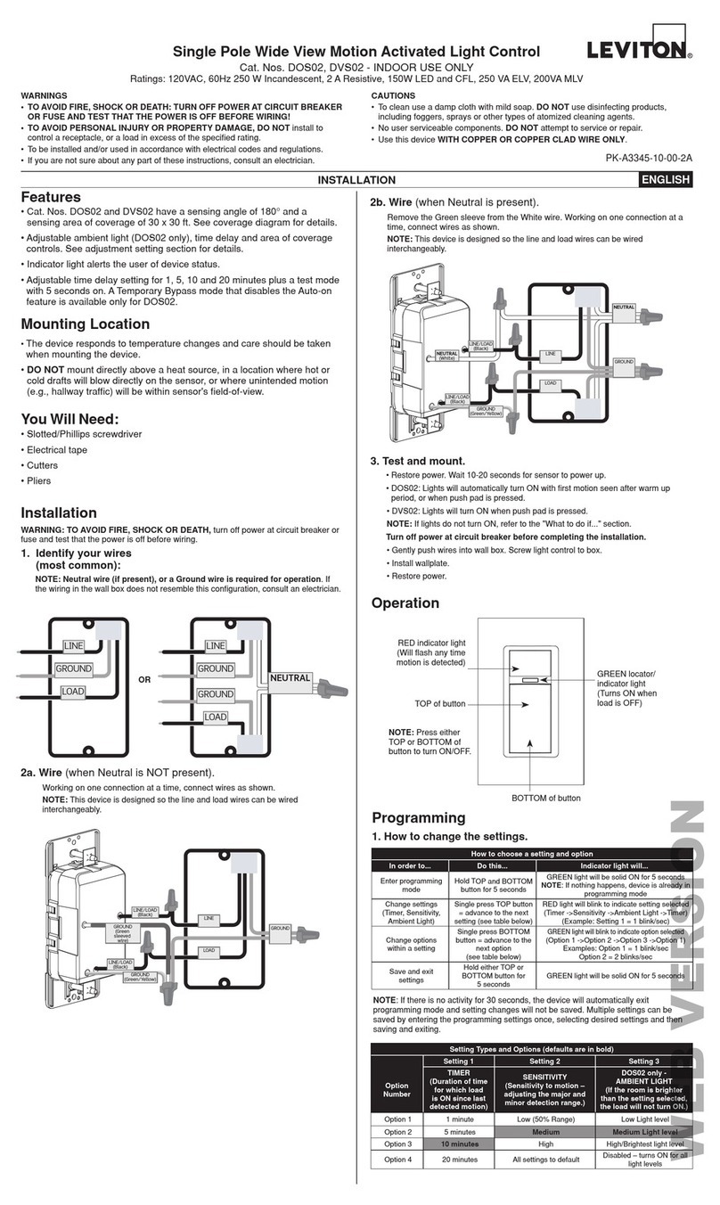
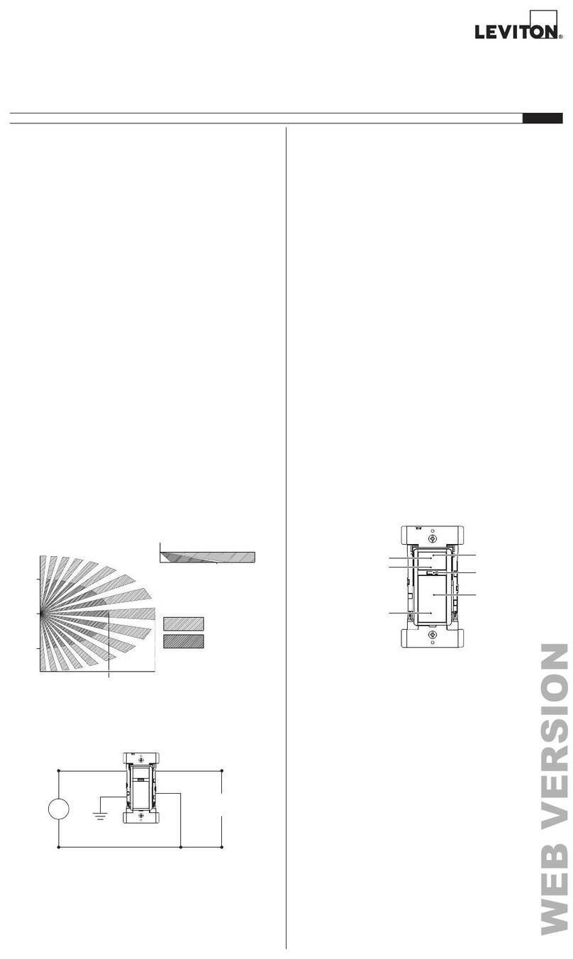
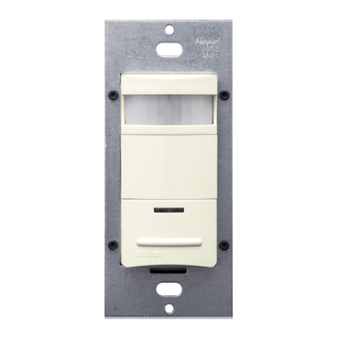
• Cat.No.IPSD6andIPVD6haveasensingareaofcoverageof
30ft.x30ft.,andasensingangleof180
O
(see Sensing Area
Coverage figure on page 2).
• Adjustablelight,time-delayandminimumlevelcontrolsare
locatedonthefrontofthedevice(See Adjustment Setting
section on page 2 for details).
• Occupancysensorcanbeconvertedtoavacancysensor
(See adjustment settings on page 2).
• LEDindicatorisusedtoalerttheuserofthestatusofthedevice.
•
AdjustableTimeDelaysettingfor30seconds,5min,15min&30min.
• Adjustablesettingforminimumlightlevel.
LOCATION / MOUNTING
Thedevicerespondstotemperaturechangesandcareshouldbe
takenwhenmountingthedevice.DO NOTmountdirectlyabovea
heatsource,inalocationwherehotorcolddraftswillblowdirectly
onthesensor,orwhereunintendedmotion(e.g.,hallwaytrafc)
willbewithinsensor’seld-of-view.
Preparing and connecting wires:
Thisdevicecanbewiredusingsidewireterminal
screws.Chooseappropriatewirestripping
specicationsaccordingly.
• Makesurethattheendsofthewiresfromthewallboxarestraight (cut if
necessary).
• Removeinsulationfromeachwireinthewallboxasshown.
• For Single Pole Application, go to Step 4A.
• For 3-Way Application with the sensor on the Load side, go to Step 4B.
• For 3-Way Application with the sensor on the Line side, go to Step 4C.
Strip Gage
(measure bare wire
here or use gage on
back of the sensor)
5/8”
(1.6 cm)
Cut
(if necessary)
Side Wire Connection
Sidewireterminalsaccept#14-12
AWGsolid copper wire only.
Step 3
Back Wire
Backwireopeningsuse#14-12
AWGsolid copper wire only.
RD
YL 3-Way
A
C
Hot (Black)
Neutral (White)
LINE/Black
LOAD
Line
120VAC
60 Hz
Sensor
Green
Ground
3-Way/
Brass
3-Way Switch
Common Terminal
(Black Screw)
Pigtail
Pigtail
Green
Ground
LOAD/Red
First Traveler
Second Traveler
3-Way Wiring with Single Pole Switch Application:
Whenconnectingthesensorfor3-waycontrol,rstchoosewhich
wallswitchlocationthesensorwillbeinstalledin.Next,identify
whichelectricalboxhasthelineconnection.Ifthelineconnection
isintheboxwherethestandard3-wayswitchislocated,usewiring
diagram4B.Ifthelineconnectionisintheboxwherethesensoris
located,usewiringdiagram4C.
NOTE: Apairofshortpigtailwireswillbeneededforconnectionto
the3-wayswitch.
Hot (Black)
Neutral (White)
LINE/Black
LOAD
Line
120VAC
60 Hz
Sensor
Green
Ground
Green
Ground
3-Way/
Brass
3-Way Switch
Common Terminal
(Black Screw)
Pigtail
Pigtail
First Traveler
Second Traveler
LOAD/
Red
BK
RD
3-Way
2
3-Way Switch
2
Sensor
1
3
5
Common
Terminal
(Black
Screw)
Ground
(Green Screw)
1
4
43
5
Common
Terminal
(Black
Screw)
Ground
(Green Screw)
BK
RD
3-Way
2
Sensor
3
5
1
4
3-Way Switch
2
1
5
4
3
BSensor is located in electrical box with LOAD
connection:
WIRING SWITCH:
Connect wires per WIRING DIAGRAM as follows:
• GreenorbarecopperwireinwallboxtoGreenterminalscrew.
• OnepigtailwiretotheBlackscrewterminalmarked"COM"and
onepigtailwiretotheBrassterminal(same side of switch).
• Connectthefollowing4wiresusinganappropriatelysized
wirenut:
1. Common/Linewire(identified in step 2).
2. SecondTravelerwire(note color from step 2).
3. Twopigtailwiresfromthe3-wayswitch.
• FirstTravelerwallboxwire(note color from step 2)to
Brassscrewterminalontheswitch(opposite side from the
Black screw).
WIRING SENSOR:
Connect wires per WIRING DIAGRAM as follows:
• GreenorbarecopperwireinwallboxtoGreenterminalscrew.
• Common/Loadwallboxwireidentiedwhenremovingold
switch(step 2)toterminalscrewmarked"BK".
• FirstTravelerwallboxwire(note color from step 2)toterminal
screwmarked"3-way".
• SecondTravelerwallboxwire(note color from step 2)to
terminalscrewmarked"RD".ThisTravelerfromtheswitchmust
gototheterminalscrewonthesensormarked"RD".
WIRING SENSOR:
Connect wires per WIRING DIAGRAM as follows:
• GreenorbarecopperwireinwallboxtoGreenterminalscrew.
• Common/Linewallboxwireidentiedwhenremovingoldswitch
(step 2)toterminalscrewmarked"BK".
• FirstTravelerwallboxwire(note color from step 2)toterminal
screwmarked"RD".
• SecondTravelerwallboxwire(note color from step 2)to
terminalscrewmarked"3-way".
WIRING SWITCH:
Connect wires per WIRING DIAGRAM as follows:
• GreenorbarecopperwireinwallboxtoGreenterminalscrew.
• OnepigtailwiretotheBlackscrewterminalmarked"COM"and
aonepigtailwiretothebrassterminal(samesideofswitch)
• Connectthefollowing4wiresusinganappropriatelysized
wirenut:
1. Common/Loadwire(identified in step 2).
2. FirstTravelerwire(note color from step 2).
3. Twopigtailwiresfromthe3-Wayswitch.
• SecondTravelerwallboxwire(note color from step 2)to
Brassscrewterminalontheswitch(opposite side from the
Black screw).
ONOFF
ONOFF
ONOFF
ONOFF
ONOFF
ONOFF
ONOFFONOFF
ONOFF
ONOFF
ONOFF
ONOFF
Step 1 WARNING:TO AVOID FIRE, SHOCK, OR
DEATH; TURN OFF POWERatcircuitbreakeror
fuseandtestthatpowerisoffbeforewiring!

LIMITED 5 YEAR WARRANTY AND EXCLUSIONS
Levitonwarrantsto theoriginal consumer purchaser and notforthebenet of anyone else that thisproduct atthetime of its salebyLevitonis freeofdefectsin materials and workmanshipundernormal and properuseforveyearsfromthe purchase date.Leviton’sonly obligation is to correctsuchdefectsbyrepair or replacement, at itsoption,if within such ve year periodthe product is returned prepaid, with
proofof purchase date, and a descriptionofthe problem to Leviton Manufacturing Co., Inc., Att: Quality Assurance Department, 201 North Service Road, Melville, New York 11747. This warranty excludesand there is disclaimed liabilityfor labor for removal of this product or reinstallation.Thiswarrantyis voidif this productis installedimproperlyor in an improper environment,overloaded, misused, opened,
abused, or altered in any manner, or is not used under normal operating conditions or not in accordance with any labels or instructions.There are no other or implied warranties of any kind, including merchantability and fitness for a particular purpose, butif any implied warranty is required by the applicable jurisdiction, the duration of any such implied warranty, including merchantability and tness for
a particular purpose, is limited to ve years.Leviton is not liable for incidental, indirect, special, or consequential damages, including without limitation, damage to, or loss of use of, any equipment, lost sales or profits or delay or failure to perform this warranty obligation.The remedies provided herein are the exclusive remedies under this warranty, whether based on contract, tort or otherwise.
PK-93918-10-00-2B©2012LevitonMfg.Co.,Inc.
• Positionallwirestoprovideroominoutletwallboxfordevice.
• Ensurethattheword"TOP"isfacingupondevicestrap.
• Partiallyscrewinmountingscrewsinwallboxmountingholes.
• Restorepoweratcircuitbreakerorfuse.
• ForIPSD6lightswillautomaticallyturnON
afterpowerisapplied.
• ForIPVD6,pressandreleasepushpadto
turnthelightsON.
See Locator Light Status chart to
confirm the operational state of the
device.
If lights still do not turn ON, refer to the
TROUBLESHOOTING section.
Testing your Device prior to mounting in
wall box:
Step 5
Restore Power:Restorepoweratcircuitbreaker
orfuse.
Installation is complete.
Step 7
Device Mounting:
TURN OFF POWER AT CIRCUIT BREAKER OR
FUSE.
Step 6
Installationmaynowbecompletedbytighteningmountingscrews
intowallbox.Attachwallplate.
Locator Light LED:
IPSD6:
LEDblinkswhenmotionisdetected.
IPVD6: LEDblinkswhenmotionisdetectedandloadisON.
LEDwillremainilluminatedwhenloadisOFF.
Enabling Kick Start
1. Pullthepushpadoutfromthebottom(toactivatetheairgapswitch).
2. Pushthepushpadgentlybackintoplaceuntilthebuttonis
pushedtoo.
3. Keepthebuttonpushedfortenseconds.
4. Devicewillblinkthelocatorledtoindicatesuccessfulprogramming.
a.CFLmode(kickstart): 2blink
b.LED/Incandescentmode: 1blink
NOTE: Dresswireswithabendas
shownindiagraminordertorelieve
stresswhenmountingdevice.
For additional information, contact Leviton’s Techline at
1-800-824-3005 or visit Leviton’s website at www.leviton.com
ThisproductiscoveredbyU.S.Pat.No.7,924,155
andcorrespondingforeignpatents.
©2012LevitonManufacturingCo.,Inc.
AllRightsIncludingTradeDressRightsReserved
TROUBLESHOOTING
Lights do not switch ON - IPSD6:
• Motionisbeyondsensingrange,moveclosertoswitch.
• Adjustthelightleveladjustmenttowardlighterordarker,
dependingonroomconditions.
Lights always stay ON:
• Checktimedelaysettingsandcomparetohowlongthelights
stayON.
• Besurethatnomotionoccursincoverageareafortime
selected.
• Checkthatswitchisnotinstallednearaheatsource
(e.g.,stove,lights,heatvents)ordetectingmotionfroman
adjacentarea(e.g.,hallwaytrafc).Ifso,switchmayhave
toberelocated.
Lights do not turn ON - IPVD6:
• Checkthatswitchisinstalledcorrectly.
• CheckthatpowerisON.
• Checkthatlightbulbisfunctioning.
The LED or CFL bulb flickers or flashes during start up:
• Verifythebulbismarked"dimmable"Thisdeviceisintendedto
operateonlydimmableLEDandCFLbulbs.
Flickering is observed at low dim level:
• SomeLEDandCFLbulbsdonotachievethesameminimum
lightlevelofincandescent.Refertosectiononadjustingthe
minimumbrightnesssettingforLEDandCFLbulbs.
CFL bulb appears to flicker:
• CFLbulbsmayrequireseveralminutesofwarmuptostabilize
thelight.
LED or CFL bulbs do not turn on:
• RefertosectiononenablingkickstartfeatureforCFLandLED
lamps.
NOTE:Ifproblemscontinue,consultanelectrician.
ADJUSTMENT SETTINGS
1. Withpowerrestoredandwallplateremoved,removefaceof
devicetoexposesettingcontrols,seecolorchangeinstructionsin
page1.Useyourngerorasmallscrewdrivertoadjustthelight
sensitivityandtimesettingsonthedeviceasfollows:
Light Level Adjustment:
• Turnthecontrolclockwise.LightswillturnONinlighter
conditions.
 • Turnthecontrolcounter-clockwise.LightswillturnONinless
lightingconditions.
•Adjustinglightlevelfullycounterclockwisewillrequiremanual
operationofthesensor.
Time Selection:
• Adjustthetimeselectortothedesiredlengthoftimethelights
aretoremainON.LightswillremainONfrom30secondsto30
minutesaftertheroomisvacated.
 • Turnthecontrolclockwise.LightswillremainONupto30
minutes(see table below).
 • Turnthecontrolcounter-clockwise.LightswillremainONupto
30seconds(see table below).
CFL & LED dimming:Thedimmerfeaturesauseradjustabledial
forsettingtheminimumlightlevel.Thisfeaturecanbeusedwith
certainlightingloadstoreduceanyickeratlowlightlevels.
Minimum Dim Level Adjustment:
• Turnthecontrolclockwise.Lightswilldimtohigherlightlevel.
 • Turnthecontrolcounterclockwise.Lightswilldimtolowerlight
level.
2. Testthatthelightlevel,timeselectionandminimumdimminglevel
aresetasdesired.Ifnot,repeatadjustmentsuntilsatised.
3. Mountwallplate.INSTALLATION IS COMPLETE.
OPERATION
REPLACING LAMPS
Light Level
Adjustment
Minimum Level
Dimming Adjustment
Time Selection 1 2
0 3
1 2
0 3
1 2
0 3
Time Settings Time
0 30Sec
1 5Min
2 15Min
3 30Min
Lens
Push
Pad
Locator
Light
LOCATOR LIGHT STATUS
LOAD IPSD6 IPVD6
OFF Blinking Lit
ON Blinking Blinking
IPSD6: Auto On
Lightswillautomaticallyturnonwhenroomisoccupiedormotionis
detected.TheIPSD6willswitchlightsoffwhennomotionisdetected
inun-occupiedroomafterasetperiodoftime.
Time delay adjustment:refertosectiononAdjustmentsettings.
TheON/OFF/DIMpushpadcanbeusedtomanuallyturnthe
lightingloadONandOFFortodimitUPandDOWN.
Dimming:
OncetheloadhasbeenturnedON,pushandholdthe
ON/OFF/DIMbuttontodimthelightsUPorDOWN.Toreversethe
dimmingdirectionmomentarilyreleasetheON/OFF/DIMbutton,then
pushandholditagain.Onceyouachievethedesiredlightlevelthe
dimmerwillre-callthepre-setdimminglevelwhenturningontheload.
Light level adjustment:Refertosectiononadjustmentsettings.
IPVD6: Manual On
OperationrequirestheusertomanuallyturnthelightsONby
depressingtheON/OFF/DIMpad.LightswillautomaticallyturnOFF
whentheroomisleftun-occupiedforasetperiodoftime.
Time Delay Adjustment:RefertosectiononAdjustmentsettings.
Dimming:O
ncetheloadhasbeenturnedON,pushandholdthe
ON/OFF/DIMbuttontodimthelightsUPorDOWN.Toreversethe
dimmingdirectionmomentarilyreleasetheON/OFF/DIMbutton,then
pushandholditagain.Onceyouachievethedesiredlightlevelthe
dimmerwillre-callthepre-setdimminglevelwhenturningontheload.
NOTE:Ina3-wayapplication,the3-wayswitchprovidestheability
tomanuallyswitchtheloadONfromasecondlocation.Thesensor
willtimeoutandswitchtheloadOFFoncemotionisnolonger
detectedandthetimedelayexpires.
TheIPSD6andtheIPVD6utilizesanAirGapIsolationfeaturewhen
replacingalamp(s)connectedtotheIPSD6ortheIPVD6,forsafety.
1. PullthebottomofthepushpadoutasshownintheFigure A
untilitlocksintoplace.ThisengagestheAirGap,whichstops
electricityfromowingtotheconnectedload.
2. Afterreplacingthelamp(s),presstheAirGapSwitch(pushpad)
sothatitreturnstotheoriginalpositionensuringitisushwith
thesurfaceoftheSensor/Dimmer(Figure B).
3. TheSensor/Dimmerwillreturntoitspre-setconditionandis
readytooperate.
SENSING AREA COVERAGE
Field-of-View (Horizontal)
Side (Vertical) Field-of-View
FCC COMPLIANCE STATEMENT
ThisdevicecomplieswithPart15oftheFCCRules.Operationissubjectto
followingtwoconditions:(1)thisdevicemaynotcauseharmfulinterference,
and(2)thisdevicemustacceptanyinterferencereceived,including
interferencethatmaycauseundesiredoperationofthedevice.
Thisequipmenthasbeentestedandfoundtocomplywiththelimitsfora
ClassBDigitalDevice,pursuanttoPart15oftheFCCRules.Theselimits
aredesignedtoprovidereasonableprotectionagainstharmfulinterference
inaresidentialinstallation.Thisequipmentgenerates,uses,andcanradiate
radiofrequencyenergyand,ifnotinstalledandusedinaccordancewith
theinstructions,maycauseharmfulinterferencetoradiocommunications.
However,thereisnoguaranteethatinterferencewillnotoccurinaparticular
installation.Ifthisequipmentdoescauseharmfulinterferencetoradioor
televisionreception,whichcanbedeterminedbyturningtheequipmentOFF
andON,theuserisencouragedtotrytocorrecttheinterferencebyoneor
moreofthefollowingmeasures:
•ReorientorrelocatethereceivingAntenna.
•Increasetheseparationbetweentheequipmentandthereceiver.
•Connecttheequipmentintoanoutletonacircuitdifferentfromthatto
whichthereceiverisconnected.
•Consultthedealeroranexperiencedradio/tvtechnicianforhelp.
FCC CAUTION
AnychangesormodicationsnotexpresslyapprovedbyLeviton
ManufacturingCo.,Inc.,couldvoidtheuser'sauthoritytooperatethe
equipment.
Engage Air Gap
A) B)
Reset Sensor/Dimmer
1.5m
5ft
30ft
9.1m
30ft
9.1m
6ft
1.7m
1.8m
6ft
5ft
1.5m
30ft
9.1m
1.4m
4ft
8.4m
27ft
2.1m
7ft
1.5m
5ft
1.2m
4ft
1.7m
6ft
2.6m
8ft
NOTE: TooperatetheIPSD6asavacancysensor(manualON/Auto
OFF)-rotatethelightleveladjustmentfullycounterclockwise.

This manual suits for next models

1

Other Leviton Security Sensor manuals

Leviton decora ODS10-TD Series User manual

Leviton

Leviton decora ODS10-TD Series User manual

Leviton CRS4K User manual

Leviton

Leviton CRS4K User manual

Leviton ODC Series User manual

Leviton

Leviton ODC Series User manual

Leviton ZLS10-IDW User manual

Leviton

Leviton ZLS10-IDW User manual

Leviton 61A00-1 Mounting instructions

Leviton

Leviton 61A00-1 Mounting instructions

Leviton decora IPV05 User manual

Leviton

Leviton decora IPV05 User manual

Leviton 47A00-2 User manual

Leviton

Leviton 47A00-2 User manual

Leviton ODC15-IDW User manual

Leviton

Leviton ODC15-IDW User manual

Leviton decora OSSMT-M3 User manual

Leviton

Leviton decora OSSMT-M3 User manual

Leviton ZLS10-ILW User manual

Leviton

Leviton ZLS10-ILW User manual

Leviton Provolt ODC10-UDW User manual

Leviton

Leviton Provolt ODC10-UDW User manual

Leviton DOS02 User manual

Leviton

Leviton DOS02 User manual

Leviton decora IPV02 User manual

Leviton

Leviton decora IPV02 User manual

Leviton GreenMAX OSR15-MCW User manual

Leviton

Leviton GreenMAX OSR15-MCW User manual

Leviton HB011-PDX User manual

Leviton

Leviton HB011-PDX User manual

Leviton Intellect Solo Sensor ZLS05-ILW User manual

Leviton

Leviton Intellect Solo Sensor ZLS05-ILW User manual

Leviton DECORA ODS15-IDI Series User manual

Leviton

Leviton DECORA ODS15-IDI Series User manual

Leviton ODSMT-MD User manual

Leviton

Leviton ODSMT-MD User manual

Popular Security Sensor manuals by other brands

VSAIL VI-6637 Installation and operation manual

VSAIL

VSAIL VI-6637 Installation and operation manual

Texecom Premier Elite AM 360DT installation manual

Texecom

Texecom Premier Elite AM 360DT installation manual

escofred SLD-300 owner's manual

escofred

escofred SLD-300 owner's manual

Mr. Beams MB750 user manual

Mr. Beams

Mr. Beams MB750 user manual

B.E.G. LUXOMAT PD9-M-DIM Installation and operating instruction

B.E.G.

B.E.G. LUXOMAT PD9-M-DIM Installation and operating instruction

Yamorc YD6016LN quick start

Yamorc

Yamorc YD6016LN quick start

Western Safety Products 66452 Instructions and precautions

Western Safety Products

Western Safety Products 66452 Instructions and precautions

Lufft SHM 31 user manual

Lufft

Lufft SHM 31 user manual

iRay Technology Luna1012X user manual

iRay Technology

iRay Technology Luna1012X user manual

GROUNDTECH Evo user manual

GROUNDTECH

GROUNDTECH Evo user manual

Honeywell SC105 installation guide

Honeywell

Honeywell SC105 installation guide

Emos G1190 manual

Emos

Emos G1190 manual

Danfoss DEVItector II V2 user guide

Danfoss

Danfoss DEVItector II V2 user guide

Scott VISION 2 RFF1000 Operating and maintenance instructions

Scott

Scott VISION 2 RFF1000 Operating and maintenance instructions

Radionics TriTech D8535 installation instructions

Radionics

Radionics TriTech D8535 installation instructions

IFM GG854S Original operating instructions

IFM

IFM GG854S Original operating instructions

Federal Signal Corporation Latitude SignalMaster SL6S installation instructions

Federal Signal Corporation

Federal Signal Corporation Latitude SignalMaster SL6S installation instructions

Sensit VMD Set-up & operating instructions

Sensit

Sensit VMD Set-up & operating instructions

manuals.online logo
manuals.online logoBrands
  • About & Mission
  • Contact us
  • Privacy Policy
  • Terms and Conditions

Copyright 2025 Manuals.Online. All Rights Reserved.