manuals.online logo
Brands
  1. Home
  2. •
  3. Brands
  4. •
  5. Optex
  6. •
  7. Security Sensor
  8. •
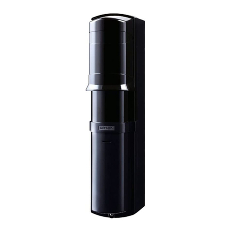
  9. Optex QX Infinity Series User manual

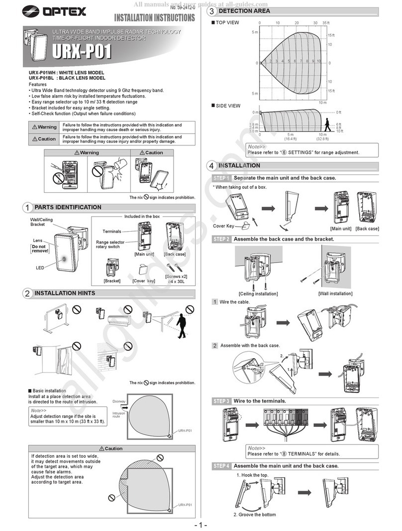
Optex QX Infinity Series User manual

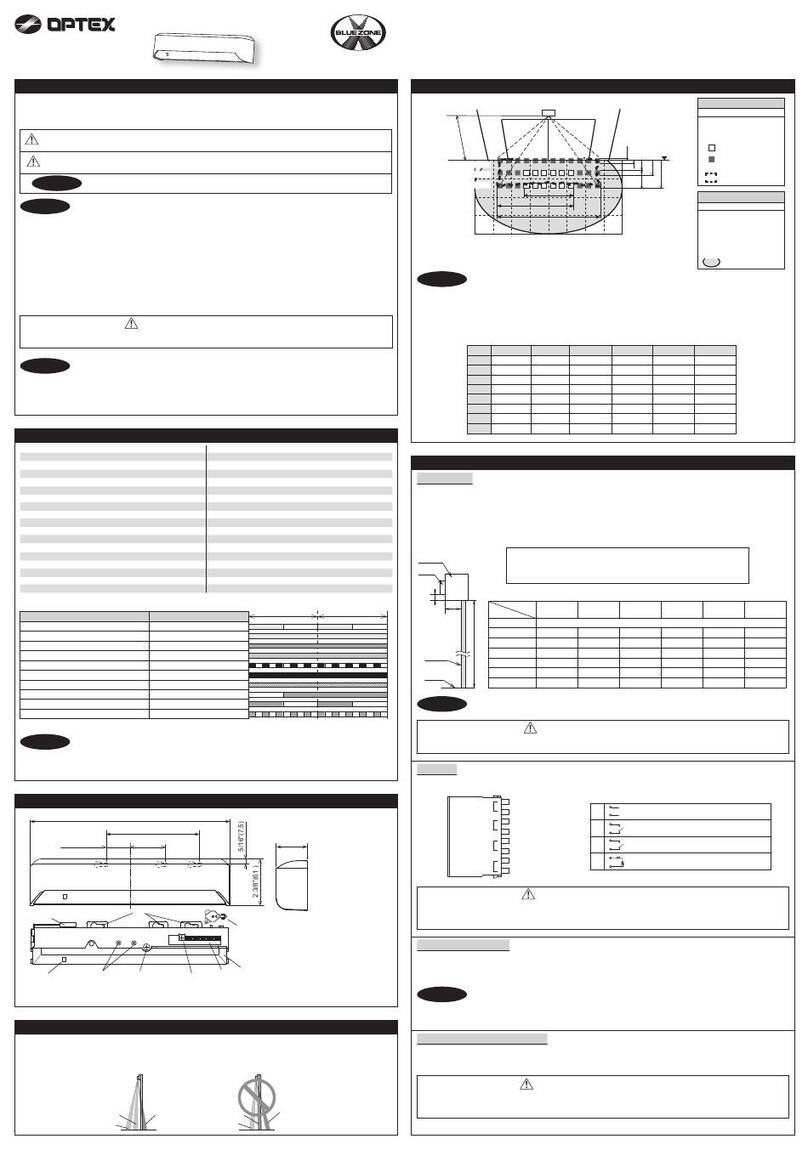
INSTALLATION INSTRUCTIONS
59-2781-0 1908-05
EN
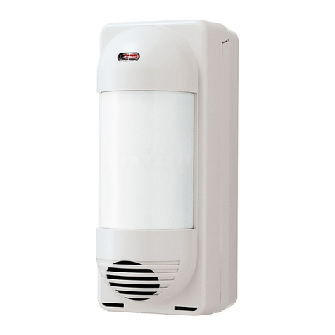
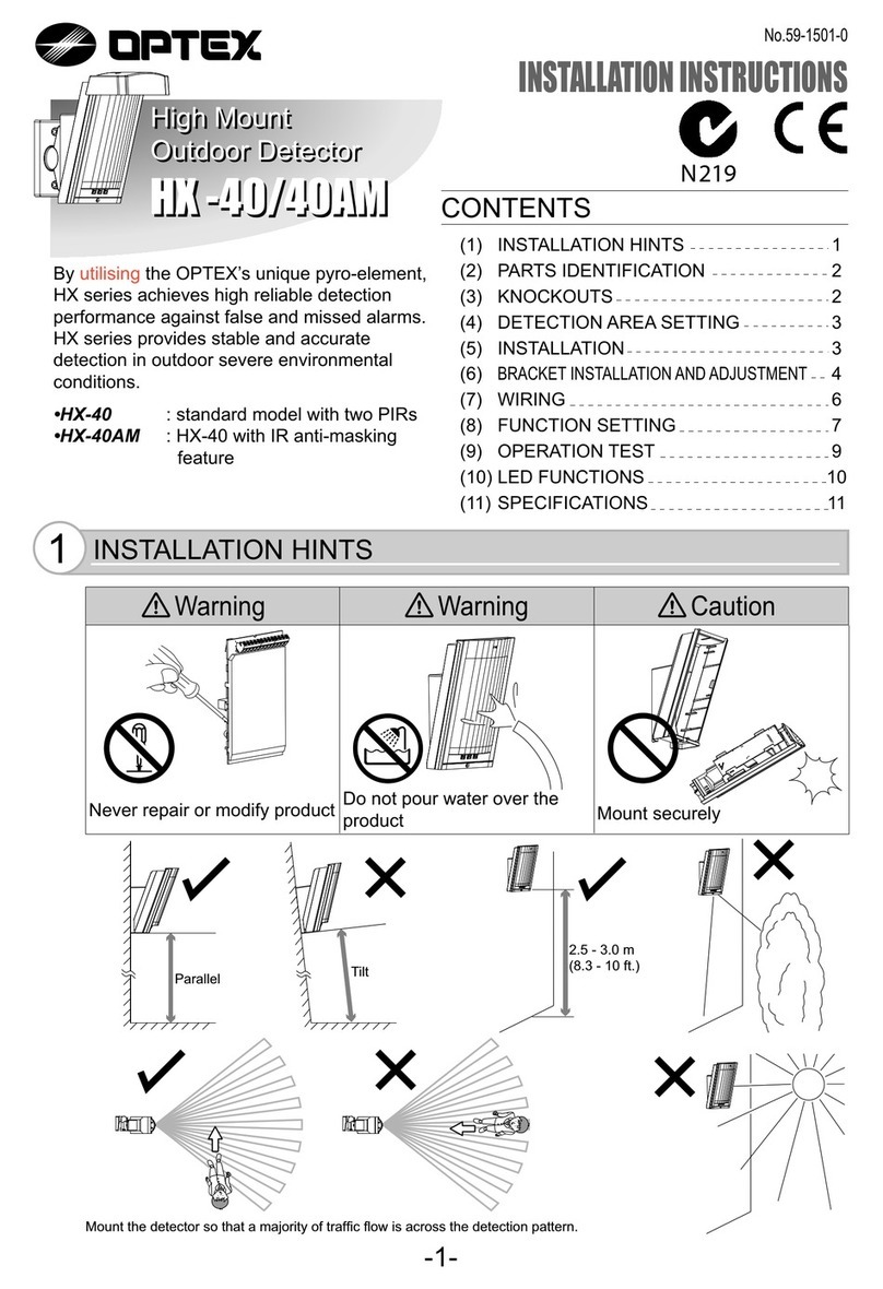
QX Infinity series
Wide Angle Outdoor Detector
QX Infinity series
QXI-R: Standard Battery Operated Model
QXI-RDT-X5: +Microwave detection (10.525 GHz)
QXI-RDT-X8: +Microwave detection (10.587 GHz)
QXI-RDT-X9: +Microwave detection ( 9.425 GHz)
BATTERY OPERATED MODEL
1Introduction
2Manufacturer s statement
!Warning Prohibited Recommended
< QXI-RDT only >
Multi Level
Pet Alley
!Caution
Mounting height
2.2 m (7 3 ) to 2.7 m (8 11 )
0.8 m (2 7 ) to 1.2 m (4 )
Tilt
PDF download
and
additional
information
with
multilanguage
,
available in;
http://navi.optex.net/manual/50337
FR
DE
IT
ES
PT
NL
Le téléchargement PDF et des informations supplémentaires multilingues sont disponibles dans l'URL indiquée.
PDF-Download und zusätzliche Informationen in mehreren Sprachen finden Sie unter der angezeigten URL.
Download PDF e ulteriori informazioni con multilingua sono disponibili nell'URL mostrato.
La descarga de PDF y la información adicional en varios idiomas están disponibles en la URL que se muestra.
PDF download e informações adicionais com multilanguage estão disponíveis no URL mostrado.
PDF-downloads en aanvullende informatie met meertalige zijn beschikbaar in de getoonde URL.
Replace the transmitter battery with the dummy
battery (included) for battery sharing.
- 1 -
3Installation
<Accessories>
30
50
90
MaximumTransmitter
Size (mm)
Connector for
TROUBLE
Dummy battery
and Connector for
ALARM
Transmitter sideMain unit side
Power
Alarm
Trouble
Red
Black
White
Yellow
Green
Blue
Red
Black
White
Yellow
Green
Blue
Connectors
Battery Life (DIP SW No.5)
Battery saving timer
QXI-R
QXI-RDT
120 5
6 5
4 3
Unit: estimated years
CR123A
(3 V DC, 1,300 mAh)
Wall tamper option
Cover
Lens
DIP switch
Base
Microwave module
(QXI-RDT only)
PIR sensor
Main unit
[1] Warm-up
[2] Alarm
[3] Walk test end
60
2
5
Seconds
LED
MW Sensitivity
Do not touch the
parts with this sign.
!
!
!
Cover lock screw
(optional)
Mirror
Tamper switch
!
How to open the cover
Lock screw
(optional)
* Remove before,
if used.
[1] Unlock the cover using a
screwdriver (-).
[2] Lift the cover up.
Battery sharing
[1] Install dummy battery
in transmitter
[2] CR123A
!Except levers
on side
<Options>
CA-2C(W)
Bracket for ceiling mount
CA-1W(W)
Bracket for wall mount
Mounting screw
(4 × 20 mm) x 3
Area masking strips
Fixing screw
for the Main unit
(3 × 12 mm) x 1
a
b
c
d
e
b
c
d
e
ff
a
b
c
d
e
f
b
c
d
e
f
L H
default
OPTEX INC./AMERICAS HQ (U.S.)
www.optexamerica.com
OPTEX (EUROPE) LTD./EMEA HQ (U.K.)
www.optex-europe.com
OPTEX TECHNOLOGIES B.V.
(The Netherlands)
www.optex.eu
OPTEX SECURITY SAS (France)
www.optex-europe.com/fr
OPTEX SECURITY Sp.z o.o. (Poland)
www.optex.com.pl
OPTEX PINNACLE INDIA,
PVT., LTD. (India)
www.optexpinnacle.com
OPTEX KOREA CO.,LTD. (Korea)
www.optexkorea.com
OPTEX (DONGGUAN) CO.,LTD.
SHANGHAI OFFICE (China)
www.optexchina.com
OPTEX (Thailand) CO., LTD. (Thailand)
www.optex.co.th
Copyright (C) 2019 OPTEX CO.,LTD.
OPTEX CO., LTD. (JAPAN)
www.optex.net
• These units are designed to detect an intruder and activate an alarm control panel.
Being only a part of a complete system, we cannot accept responsibility for any damages or
other consequences resulting from an intrusion.
• Specifications and designs are subject to change without prior notice.
12.0 m (40') 120°wide
Multi level:40 zones
Pet alley:18 zones
0.3 to 2.0 m/s (1' to 6'7"/s)
2.0℃( 3.6°F) at 0.6 m/s
Remove lower area detection to avoid small animals.
CR123A (3 V DC) *Not included.
9 µA stand-by 16µA stand-by
11 mA max. at 3 V DC 11 mA max. at 3 V DC
2.0 ± 0.5 s
Approx. 60 s (LED blinks)
N.C/N.O. switchable solidstate switch, 3 V DC 0.01 A max.
[1] Warm-up [2] Alarm [3] Walk test end
-40℃to +60℃(-40°F to +140°F) -40℃to +45℃(-40°F to +113°F)
95% max.
IP 54
Wall (Outdoor, Indoor)
Multi level:2.2 to 2.7 m (7' 3" to 8'11")
Pet alley: 0.8 to 1.2 m (2' 7" to 4' )
215 g (7.58 oz) 230 g (8.11 oz)
[1] Dummy battery and connector for ALARM
[2] Connector for TROUBLE [3] Mounting screw (4 x 12 mm) x 3
[4] Lock screw (3 x 12 mm) x 1 [5] Area masking strips
Model
Detection method
PIR coverage
PIR zones
Detectable speed
Sensitivity
Pet alley
Power source
Current draw
Alarm period
Warm-up period
Alarm output
Trouble output
(with tamper)
LED indicator
Operation temperature
Environment humidity
Internation protection
Mounting
Mounting height
Weight
Accessories
QXI-R
Passive infrared
QXI-RDT
Passive infrared & Microwave
EU contact information
Manufacturer:
OPTEX CO., LTD.
5-8-12 Ogoto, Otsu, Shiga, 520-0101 JAPAN
Authorized representative in Europe:
OPTEX (EUROPE) LTD./EMEA HEADQUARTERS
Unit 13, Cordwallis Park, Clivemont Road,
Maidenhead, Berkshire, SL6 7BU U.K.
■OPTEX declares that QXI-RDT-X5, QXI-RDT-X8 and QXI-RDT-X9 comply with RE Directive
2014/53/EU. Doc documents can be found on our website; www.optex.net
■
Microwave emission Frequency and Power
QXI-RDT-X5: 10.525 GHz 15.78 mW e.i.r.p
QXI-RDT-X8: 10.587 GHz 8.93 mW e.i.r.p
QXI-RDT-X9: 9.425 GHz x.xx mW e.i.r.p
■
The following list indicates the areas of intended use of the equipment and any known
restrictions. For countries not included in this list, please consult the responsible
Spectrum Management Agency.
10.525 GHz: Belgium, Denmark, Finland, Germany, Greece, Italy, Luxembourg,
The Netherlands, Spain, Sweden, Iceland, Norway, Switzerland
10.587 GHz: Belgium, France, Germany, Ireland, Luxembourg, The Netherlands,
United Kingdom
9.425 GHz: Austria, Czechia, Esthonia, Germany, Slovakia, Turkey, Russia
■QXI-RDT-X5, QXI-RDT-X8 and QXI-RDT-X9 also comply with EU radiation exposure limits
set forth for an uncontrolled
environment. This equipment should be installed and
operated with minimum distance
20 cm between the radiator & your body.
- 2 -
5Specifications
5-1. Specifications 5-2. Dimensions 78(3.07) 83.5 (3.28)
144.5 (5.69)
Unit: mm (inch)
LED flashes 5 times
33
3
DIP switch ON OFF
Future use
Battery
saving timer 5 s 120 s
See right for the PIR sensitivity
Alarm output N.O. N.C.
LED ON OFF
1
2
3
4 5 6 7 8
[8]
[7]
[6]
[5]
[4]
[3]
[2]
[1]
Default settings
[2]
4Settings
4-3. Walk test
[1] Close cover [2] Walk test (3 minutes) [3] Walk test ends
With the cover open, the tamper activates.
This enables the LED function, regardless of DIP switch [1] setting.
When the cover is closed, the Walk test timer starts and automatically returns
to the normal mode after 3 minutes.
If the unit is powered up with the cover closed, it will not enter walk test mode.
Open and close the cover once to activate the walk test timer.
NOTE
4-2. DIP switch settings
3 43 4 3 43 4
L
M
PIR sensitivity
H
SH
Default
[1] Loosen the lock screw.
[2] Slide the Main unit down.
[3] Rise the mirror up to the fixing position.
[4] Tighten the lock screw as before.
[1], [4] [3]
4-1. Detection area
Top view
Side view
Side view
30 35
25
0
10
912 m
4
7.5 m
2
0
2
510 20
15
3
4
6
40 ft.
5
15
25 ft.
7.5 m
5
10
15
25 ft.
0
0
20
6
6 20
35
30
25
9
20
6
2.2 m
0
1510
5
0
312 m
40 ft
2.7 m
35
30
25
9
20
6
0.8 m
0
15
10
5
0
312 m
40 ft
1.2 m
Multi Level
Pet Alley PIR
MW
PIR
MW
PIR
MW

This manual suits for next models

4

Other Optex Security Sensor manuals

Optex FX-50QZ User manual

Optex

Optex FX-50QZ User manual

Optex ELITE T User manual

Optex

Optex ELITE T User manual

Optex OVS-01GT User manual

Optex

Optex OVS-01GT User manual

Optex VX SHIELD Series User manual

Optex

Optex VX SHIELD Series User manual

Optex SX-360Z User manual

Optex

Optex SX-360Z User manual

Optex WFX-360HW User manual

Optex

Optex WFX-360HW User manual

Optex AP-20NB(C) User manual

Optex

Optex AP-20NB(C) User manual

Optex HX-80N User manual

Optex

Optex HX-80N User manual

Optex OA-EDGE T User manual

Optex

Optex OA-EDGE T User manual

Optex WXI-R User manual

Optex

Optex WXI-R User manual

Optex FTN-R User manual

Optex

Optex FTN-R User manual

Optex LX-402 User manual

Optex

Optex LX-402 User manual

Optex OVS-6000 User manual

Optex

Optex OVS-6000 User manual

Optex URX-P01 User manual

Optex

Optex URX-P01 User manual

Optex DX-40 User manual

Optex

Optex DX-40 User manual

Optex CDX-AM Quick start guide

Optex

Optex CDX-AM Quick start guide

Optex AX-350DH MK III User manual

Optex

Optex AX-350DH MK III User manual

Optex OA-6500S T User manual

Optex

Optex OA-6500S T User manual

Optex VX SHIELD Series User manual

Optex

Optex VX SHIELD Series User manual

Optex OML-ST User manual

Optex

Optex OML-ST User manual

Optex Boundary Gard BX-80N Manual

Optex

Optex Boundary Gard BX-80N Manual

Optex REDSCAN mini-Pro Series Service manual

Optex

Optex REDSCAN mini-Pro Series Service manual

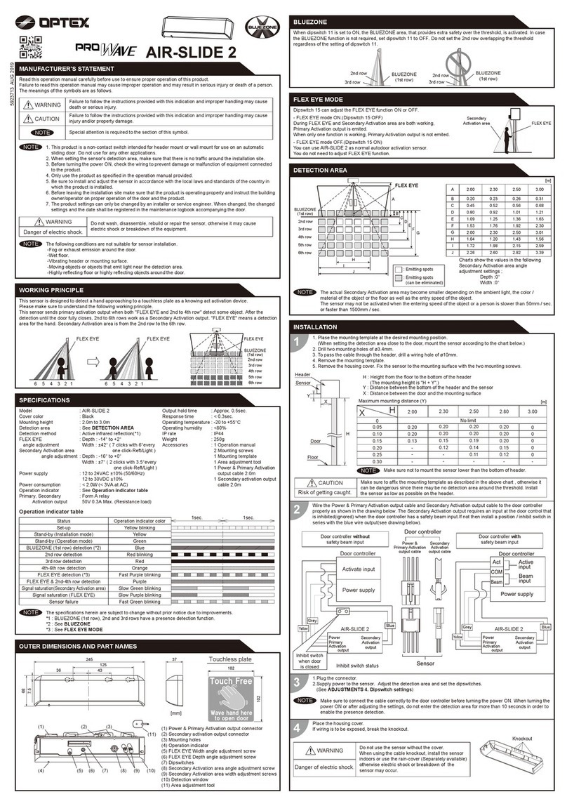
Optex PROWAVE AIR-SLIDE 2 User manual

Optex

Optex PROWAVE AIR-SLIDE 2 User manual

Optex AP-360BR User manual

Optex

Optex AP-360BR User manual

Popular Security Sensor manuals by other brands

Nationwide Industries The Protector NW308 Installation, adjustment and maintenance instructions

Nationwide Industries

Nationwide Industries The Protector NW308 Installation, adjustment and maintenance instructions

CS Instruments LD 450 instruction manual

CS Instruments

CS Instruments LD 450 instruction manual

Facom SLS.G13 instruction manual

Facom

Facom SLS.G13 instruction manual

SUREN M-TEC CDP-808 Installation, operation and specification manual

SUREN

SUREN M-TEC CDP-808 Installation, operation and specification manual

CENS PROFLEX DX5 Quick start guides

CENS

CENS PROFLEX DX5 Quick start guides

CSP Pacific BarrierGuard 800 installation manual

CSP Pacific

CSP Pacific BarrierGuard 800 installation manual

Keysight Technologies 423B Operating and service manual

Keysight Technologies

Keysight Technologies 423B Operating and service manual

STEINEL DALI-2 IS 3360 Information

STEINEL

STEINEL DALI-2 IS 3360 Information

jablotron JA-151P-WG Installation

jablotron

jablotron JA-151P-WG Installation

Vega EL 8 operating instructions

Vega

Vega EL 8 operating instructions

Bosch GMS 120 Original instructions

Bosch

Bosch GMS 120 Original instructions

MSA altair 5 Quick start card

MSA

MSA altair 5 Quick start card

Bosch ISC-BDL2-WP6 installation guide

Bosch

Bosch ISC-BDL2-WP6 installation guide

clare ClareOne CLR-C1-CO Installation sheet

clare

clare ClareOne CLR-C1-CO Installation sheet

ST Group ST 401 'CAYMAN' operating manual

ST Group

ST Group ST 401 'CAYMAN' operating manual

Chauvin Arnoux C.A 771 user manual

Chauvin Arnoux

Chauvin Arnoux C.A 771 user manual

Safety Technology International STI-7535MED Quick installation

Safety Technology International

Safety Technology International STI-7535MED Quick installation

DEFA LedgeCircle RF manual

DEFA

DEFA LedgeCircle RF manual

manuals.online logo
manuals.online logoBrands
  • About & Mission
  • Contact us
  • Privacy Policy
  • Terms and Conditions

Copyright 2025 Manuals.Online. All Rights Reserved.