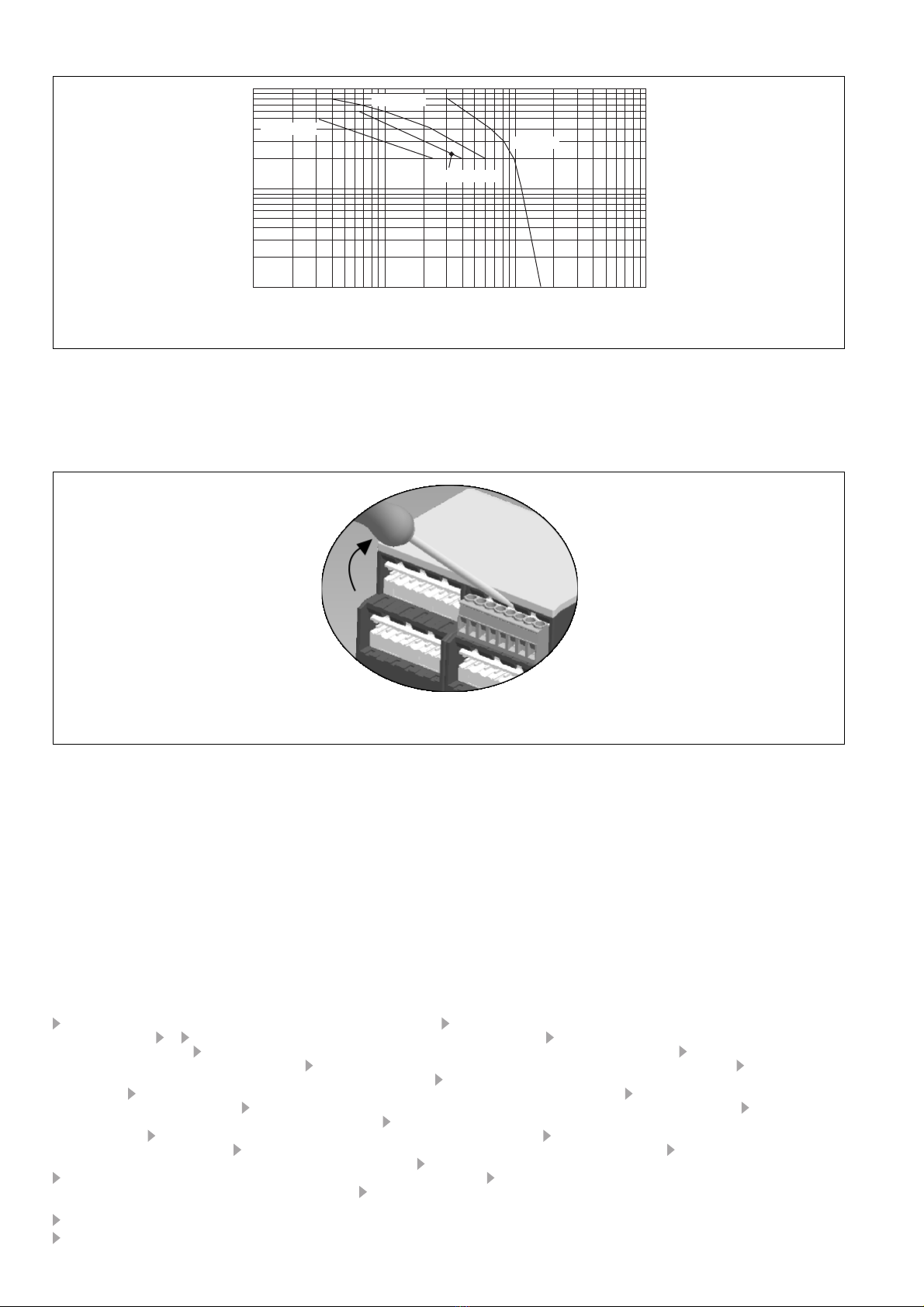
Pilz PNOZ X2.1VP User manual

- 1 -
Safety Regulations
• The unit may only be installed and
operated by personnel who are familiar
with both these instructions and the current
regulations for safety at work and accident
prevention. Follow VDE and local
regulations especially as regards
preventative measures.
•
Transport, storage and operating
conditions should all conform to
EN 60068-2-6.
• Any guarantee is void following opening of
the housing or unauthorised modifications.
• The unit should be panel mounted,
otherwise dampness or dust could lead to
function impairment.
• Adequate protection must be provided on
all output contacts especially with
capacitive and inductive loads.
Sicherheitsbestimmungen
• Das Gerät darf nur von Personen installiert
und in Betrieb genommen werden, die mit
dieser Betriebsanleitung und den gel-
tenden Vorschriften über Arbeitssicherheit
und Unfallverhütung vertraut sind.
Beachten Sie die VDE- sowie die örtlichen
Vorschriften, insbesondere hinsichtlich
Schutzmaßnahmen.
• Beim Transport, der Lagerung und im
Betrieb die Bedingungen nach EN 60068-2-
6 einhalten (s. technische Daten).
• Durch Öffnen des Gehäuses oder eigen-
mächtige Umbauten erlischt jegliche Ge-
währleistung.
• Montieren Sie das Gerät in einen Schalt-
schrank; Staub und Feuchtigkeit können
sonst zu Beeinträchtigungen der Funktio-
nen führen.
• Sorgen Sie an allen Ausgangskontakten
bei kapazitiven und induktiven Lasten für
eine ausreichende Schutzbeschaltung.
Conseils préliminaires
• La mise en oeuvre de l’appareil doit être
effectuée par une personne spécialisée en
installations électriques, en tenant compte
des prescriptions des différentes normes
applicables (NF, EN, VDE...) notamment
au niveau des risques encourus en cas de
défaillance de l’équipement électrique.
• Respecter les exigences de la norme
EN 60068-2-6 lors du transport, du
stockage et de l'utilisation de l'appareil.
• L’ouverture de l’appareil ou sa modification
annule automatiquement la garantie.
• L’appareil doit être monté dans une ar-
moire; l’humidité et la poussière pouvant
entraîner des aléas de fonctionnement.
• Vérifiez que le pouvoir de coupure des
contacts de sortie est suffisant en cas de
circuits capacitifs ou inductifs.
Bestimmungsgemäße Verwendung
Das Sicherheitsschaltgerät dient dem
sicherheitsgerichteten Unterbrechen eines
Sicherheitsstromkreises. Das Sicherheits-
schaltgerät erfüllt Forderungen der
EN 60947-5-1, EN 60204-1 und VDE 0113-1
und darf eingesetzt werden in Anwendungen
mit
• Not-Halt-Tastern
• Schutztüren
Das Gerät ist nicht für die Absicherung von
berührungslosen Verdeckungen geeignet, da
• kein dynamischer Start möglich ist.
• Gerät während dem Ablauf der Rückfall-
verzögerung gestartet werden kann.
Beachten Sie unbedingt die Sicherheitsab-
stände nach EN 294 und die Mindestabstän-
de nach EN 349.
Gerätebeschreibung
Das Sicherheitsschaltgerät PNOZ X2.1VP ist
in einem S-99-Gehäuse untergebracht. Die
Versorgungsspannung beträgt 24 V DC.
Merkmale:
• Relaisausgänge: 2 Sicherheitskontakte
(Schließer), zwangsgeführt, rückfall-
verzögert
• Anschlussmöglichkeit für Not-Halt-Taster,
Schutztürgrenztaster und Starttaster
• Statusanzeigen
• Halbleiterausgang für Reglersteuerung
• Start während Ablauf der Rückfall-
verzögerung möglich
• Überwachung externer Schütze möglich
• keine galvanische Trennung
Das Schaltgerät erfüllt folgende Sicherheits-
anforderungen:
• Schaltung ist redundant mit Selbstüberwa-
chung aufgebaut.
Domaines d’utilisation
Le bloc logique de sécurité sert à interrompre
en toute sécurité un circuit de sécurité. Le
bloc logique de sécurité satisfait aux
exigences des normes EN 60947-5-1,
EN 60204-1 et VDE 0113-1 et peut être
utilisé dans des applications avec des
• poussoirs d'arrêt d'urgence
• protecteurs mobiles
Le relais n’est pas adapté pour la
surveillance de barrages immatériels car
• un réarmement dynamique n’est pas
possible.
• le réarmement du relais est possible
pendant l’écoulement de la temporisation
à la retombée.
Veuillez respecter impérativement les
distances de sécurité d’après la
norme EN 294 et les distances minimales
d’après la norme EN 349.
Description de l’appareil
Inséré dans un boîtier S-99, le bloc logique
de sécurité PNOZ X2.1VP est alimenté en
24 V DC.
Particularités :
• Sorties disponibles : 2 contacts à
fermeture de sécurité, temporisés à la
retombée
• Bornes de raccordement pour poussoirs
AU, détecteurs de position et poussoir de
validation
• LEDs de visualisation
• Sortie statique pour variateur
• Le réarmement du relais est possible
pendant l’écoulement de la temporisation
à la retombée.
• Auto-contrôle des contacteurs externes
possible
• pas d'isolation galvanique
Authorised Applications
The safety relay provides a safety-related
interruption of a safety circuit. The safety
relay meets the requirements of EN 60947-5-
1, EN 60204-1 and VDE 0113-1 and may be
used in applications with
• E-STOP pushbuttons
• Safety gates
The unit is not suitable for use with non-
contact guards, e.g. ESPE as
• a dynamic start is not possible.
• the unit can be reset during delay-on de-
energisation.
Safety distances in accordance with EN 294
and minimum distances in accordance with
EN 349 must be observed.
Description
The Safety Relay PNOZ X2.1VP is enclosed
in a S-99 housing. The version available is
for 24 V DC operation only.
Features:
• Relay outputs: 2 safety contacts (N/O),
positive-guided, delay-on de-energised
• Connections for Emergency Stop Button,
Safety Gate Limit Switch and Reset button
• Status Indicators
• Semiconductor output for variable
frequency inverter
• reset during delay-on de-energisation
possible
• Feedback Control Loop for monitoring of
external contactors/relays possible
• No galvanic separation
The relay complies with the following safety
requirements:
• The circuit is redundant with built-in self-
monitoring.
20 211-04
PNOZ X2.1VP
4D Betriebsanleitung
4GB Operating instructions
4F Manuel d'utilisation

- 2 -
• Sicherheitseinrichtung bleibt auch bei
Ausfall eines Bauteils wirksam.
• Bei jedem Ein-Aus-Zyklus der Maschine
wird automatisch überprüft, ob die Relais
der Sicherheitseinrichtung richtig öffnen und
schließen.
• Durch geeignete Schaltungsmaßnahmen ist
sichergestellt, dass auch bei Ausfall eines
Bauteils die aktivierte Rückfallverzögerung
maximal 1,5 s beträgt.
Funktionsbeschreibung
Das Schaltgerät PNOZ X2.1VP dient dem
sicherheitsgerichteten Unterbrechen eines
Sicherheitsstromkreises. Nach Anlegen der
Versorgungsspannung leuchtet die LED
"POWER". Das Gerät ist betriebsbereit, wenn
der Startkreis S33-S34 geschlossen ist.
• Eingangskreis geschlossen (z. B. Not-Halt-
Taster nicht betätigt):
Relais K1 und K2 gehen in Wirkstellung und
halten sich selbst. Die Statusanzeigen für
"CH.1" und "CH.2" leuchten. Die Sicher-
heitskontakte 27-28/37-38 sind geschlossen.
Der Halbleiterausgang Y11-Y12 leitet und die
Statusanzeige "ON" leuchtet.
• Eingangskreis wird geöffnet (z. B. Not-Halt-
Taster betätigt):
Der Halbleiterausgang sperrt (<50 ms). Die
Statusanzeige "ON" erlischt. Nach Ablauf
der Rückfallverzögerung fallen Relais K1
und K2 in die Ruhestellung zurück. Die
Statusanzeige für "CH.1" und "CH.2"
erlischt. Die Sicherheitskontakte
27-28/37-
38
werden redundant geöffnet.
Modes de fonctionnement
• Commande par 1 canal : conforme aux
prescriptions de la EN 60204/1, pas de
redondance dans le circuit d’entrée. La
mise à la terre du circuit de réarmement
est détectée. En cas de mise à la terre des
circuits d'entrée, le fusible électronique
déclenche.
• Commande par 2 canaux: circuit d’entrée
redondant. La mise à la terre et les courts-
circuits entre les contacts sont détectées.
• Réarmement automatique : le relais est
activé dès la fermeture des canaux
d’entrée.
• Réarmement manuel: le relais n’est activé
qu’après une impulsion sur un poussoir de
validation.
• Augmentation du nombre de contacts ou
du pouvoir de coupure par l’utilisation de
contacteurs externes.
Operating Modes
• Single-channel operation: Input wiring
according to VDE 0113 part 1 and
EN 60204-1, no redundancy in the input
circuit. Earth faults are detected in the
reset circuit. Earth faults in the
Emergency Stop circuit trigger the internal
electronic fuse.
• Two-channel operation: Redundancy in
the input circuit. Earth faults in the
Emergency Stop circuit and shorts across
the emergency stop push button are also
detected.
• Automatic reset: Unit is active as soon as
the input circuit is closed.
• Manual reset: Unit is only active when a
start button has been pressed.
• Increase in the number of available
contacts by connection of external
contactors/relays.
Betriebsarten:
• Einkanaliger Betrieb: Eingangsbeschaltung
nach VDE 0113 -1 und EN 60204-1; keine
Redundanz im Eingangskreis; Erdschlüsse
im Startkreis werden erkannt. Bei
Erdschlüssen im Not-Halt-Kreis löst die
Sicherung der Versorgungsspannung aus.
• Zweikanaliger Betrieb: redundanter Ein-
gangskreis, Erdschlüsse im Tasterkreis
und Querschlüsse zwischen den Taster-
kontakten werden erkannt.
• Automatischer Start: Gerät ist aktiv, sobald
Eingangskreis geschlossen ist.
• Manueller Start: Gerät ist erst dann aktiv,
wenn ein Starttaster betätigt wird.
• Kontaktvervielfachung und -verstärkung
durch Anschluss von externen Schützen.
• The safety function remains effective in the
case of a component failure.
• The correct opening and closing of the
safety function relays is tested
automatically in each on-off cycle.
• Appropriate measures ensure that, in case
of a component failure, the activated
delay-on de-energisation is a maximum of
1.5 s.
Function Description
The relay PNOZ X2.1VP provides a safety-
oriented interruption of a safety circuit. When
the operating voltage is supplied the LED
"POWER" is illuminated. The unit is ready for
operation, when the reset circuit S33-S34 is
closed.
• Input Circuit closed (e.g. the Emergency
Stop button is not pressed):
Relays K1and K2 energise and retain
themselves. The status indicators for
"CH.1" and "CH.2" illuminate. The safety
contacts (
27-28/37-38
) are closed. The
semi-conductor Y11-Y12 conducts and the
status indicator "ON" illuminates.
• Input Circuit is opened (e.g. Emergency
Stop is pressed):
The semi-conductor Y11-Y12 switches off
(<50 ms). The status indicator "ON" goes
out. Following the delay-on de-
energisation period, relays K1 and K2 de-
energise. The status indicators for "CH.1"
and "CH.2" go out. The safety contacts
(27-28/37-38) will be opened (redundant).
Le relais PNOZ X2.1VP répond aux
exigences suivantes :
• conception redondante avec auto-
surveillance
• sécurité garantie même en cas de
défaillance d’un composant
• test cyclique (ouverture/fermeture des
relais internes) à chaque cycle Marche/
• La conception interne du relais permet de
garantir que la temporisation à la retombée
sera d’une durée max. de 1,5 s même en
cas de défaillance d’un composant interne.
Description du fonctionnement
Le relais PNOZ X2.1VP assure de façon
sure, l’ouverture d’un circuit de sécurité. A la
mise sous tension du relais (A1-A2), la LED
"POWER" s'allume. Le relais est activé si le
circuit de réarmement S33-S34 est fermé.
• Circuits d'entrée fermés (poussoir AU non
actionné) :
Les relais K1 et K2 passent en position
travail et s'auto-maintiennent. Les LEDs
"CH.1" et CH.2" s'allument. Les contacts
de sécurité (
27-28/37-38
) sont fermés.
La
sortie statique Y11-Y12 est passante et
le
LED "ON" s'allume.
• Circuits d'entrée ouverts (poussoir AU
actionné) :
La sortie statique Y11-Y12
est bloquée
(<50 ms). Le LED "ON" s'éteingne. Au
bout de la temporisation, les relais K1 et
K2 retombent. Les LEDs "CH.1" et "CH.2"
s'éteingnent. Les contacts de sécurité (27-
28, 37-38) s'ouvrent.
A1 (L+) A2 (L-)
S22
S31
S21
S32
S33 27
28
K1
K2
37
38
S34
Start
Unit
Start
Unit
S11 S12
Y11 &
Y12
Fig. 1: Innenschaltbild/Internal Wiring Diagram/
Schéma de principe

- 3 -
Montage
Das Sicherheitsschaltgerät muss in einen
Schaltschrank mit einer Schutzart von mind.
IP54 eingebaut werden. Zur Befestigung auf
einer Normschiene dient ein Rastelement auf
der Rückseite des Geräts. Sichern Sie das
Gerät bei Montage auf einer senkrechten
Tragschiene (35 mm) durch ein Halteelement
wie z. B. Endhalter oder Endwinkel.
Inbetriebnahme
Beachten Sie bei der Inbetriebnahme:
• Der Einsatz des Halbleiterausgangs ist für
sichere Anwendungen unzulässig.
•Vor die Ausgangskontakte eine
Sicherung (s. techn. Daten) schalten,
um das Verschweißen der Kontakte zu
verhindern.
• Berechnung der max. Leitungslänge Imax im
Eingangskreis:
R
lmax
R
l
/ km
I
max
=
Rlmax = max. Gesamtleitungs-
widerstand (s. technische Daten)
Rl/km = Leitungswiderstand/km
• Da die Funktion Querschlusserkennung
nicht einfehlersicher ist, wird sie von Pilz
während der Endkontrolle geprüft. Eine
Überprüfung nach der Installation des
Geräts ist wie folgt möglich:
1. Gerät betriebsbereit (Ausgangskontakte
geschlossen)
2. Die Testklemmen S12-S22 zur
Querschlussprüfung kurzschließen.
3. Die Sicherung im Gerät muss auslösen
und die Ausgangskontakte öffnen.
Leitungslängen in der Größenordnung der
Maximallänge können das Auslösen der
Sicherung um bis zu 2 Minuten verzögern.
4. Sicherung wieder zurücksetzen: den
Kurzschluss entfernen und die Versor-
gungsspannung für ca. 1 Minute abschal-
ten.
• Leitungsmaterial aus Kupferdraht mit einer
Temperaturbeständigkeit von 60/75 °C
verwenden.
• Angaben im Kapitel „Technische Daten“
unbedingt einhalten.
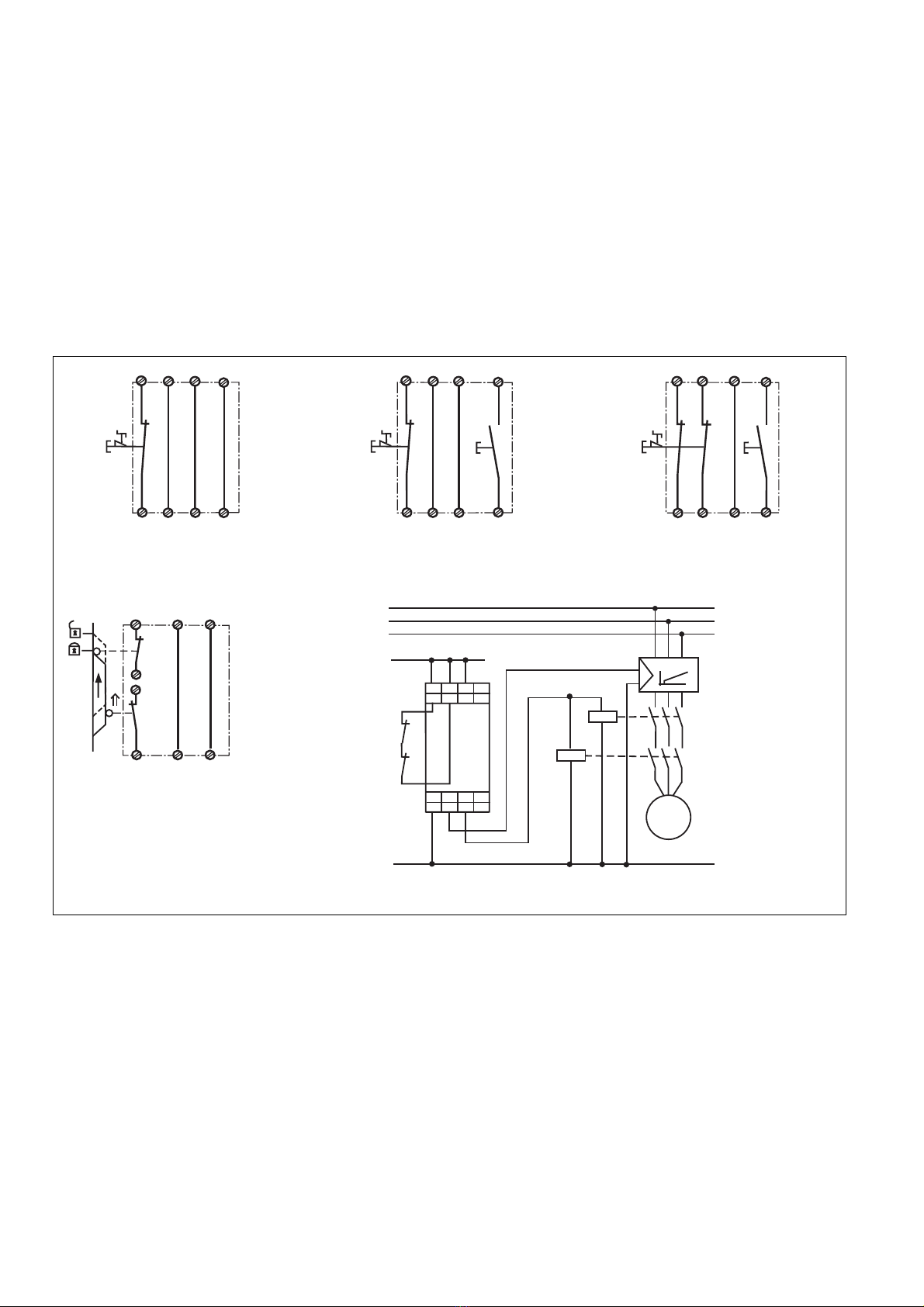
Ablauf:
• Versorgungsspannung:
Versorgungsspannung an Klemmen A1
und A2 anlegen.
• Startkreis:
- Automatischer Start: S33-S34 brücken.
- Manueller Start: Taster an S33-S34
anschließen.
• Eingangskreis:
- Einkanalig:
Öffnerkontakt von Auslöseelement an
S11 und S12 anschließen, S21-S22 und
S31-S32 brücken.
- Zweikanalig: Öffnerkontakt von Auslöse-
element an S21-S22 und S31-S32
anschließen und S11-S12 brücken.
•
Rückführkreis:
Externe Schütze in Reihe zu Startkreis
S33-S34 anschließen.
Die Sicherheitskontakte sind aktiviert (ge-
schlossen), der Halbleiterkontakt leitet. Die
Statusanzeigen für "CH.1", "CH.2" und "ON"
leuchten. Das Gerät ist betriebsbereit.
Wird der Eingangskreis geöffnet, sperrt der
Halbleiterausgang sofort und die
Sicherheitskontakte 27-28/37-38 öffnen
nach Ablauf der Rückfallverzögerung. Die
Statusanzeige erlischt.
Montage
Le relais doit être monté en armoire ayant un
indice de protection mini IP54. Sa face
arrière permet un montage sur rail DIN.
Immobilisez l'appareil monté sur un rail DIN
vertical (35 mm) à l'aide d'un élément de
maintien comme par ex. un support ou une
équerre terminale.
Mise en oeuvre
Remarques préliminaires :
• L’utilisation de la sortie statique est
interdite pour des fonctions de sécurité.
•Protection de contacts de sortie par des
fusibles (voir les caractéristiques
techniques) normaux pour éviter leur
soudage
• Calcular les longueurs de câblage max Imax
dans le circuit d’entrée:
R
lmax
R
l
/ km
I
max
=
Rlmax = résistivité de câblage totale max.
(voir les caractéristiques techniques)
Rl/km = résistivité de câblage/km
• La fonction de détection de court-circuit est
testé par Pilz lors du contrôle final. Un test
sur site est possible de la façon suivante :
1. Appareil en fonction (contacts de sortie
fermés)
2. Court-circuiter les bornes de
raccordement nécessaires au test S12-
S22
3. Le fusible interne du relais doit
déclencher et les contacts de sortie
doivent s‘ouvrir. Le temps de réponse du
fuisible peut aller jusqu‘à 2 min. si les
longueurs de câblage sont proches des
valeurs maximales.
4. Réarmement du fusible : enlever le
court-circuit et couper l‘alimentation du
relais pendant au moins 1 min.
• Utiliser uniquement des fils de cablâge en
cuivre 60/75 °C.
• Respecter les données indiquées dans le
chap. „Caractéristiques techniques“.
Mise en oeuvre :
• Tension d’alimentation:
amener la tension d’alimentation sur A1 et
A2
• Circuit de réarmement:
- Réarmement automatique: pontage des
bornes S33-S34
- Réarmement manuel : câblage d'un
poussoir sur S33-S34
• Circuits d’entrée:
- Commande par 1 canal : câblage des
contacts à ouverture entre S11-S12,
pontage des bornes S21-S22 et S31-
S32.
- Commande par 2 canaux: câblage des
contacts à ouverture entre S21-S22 et
S31-S32 et pontage des bornes S11-
S12.
• Boucle de retour:
Câblage en série des contacts externes
dans le circuit de rèarmement S33-S34
Les contacts de sécurité se ferment,
la sortie
statique est passante
. Les LEDs "CH.1" et
"CH.2" et "ON" sont allumées. L’appareil est
prêt à fonctionner.
Si le circuit d’entrée est ouvert,
la sortie
statique Y11-Y12
est bloquée tout de suite et
les contacts de sécurité retombent au bout
de la temporisation. Les LEDs s’éteignent.
Installation
The safety relay must be panel mounted
(min. IP54). There is a notch on the rear of
the unit for DIN-Rail attachment.
If the unit is installed on a vertical mounting
rail (35 mm), ensure it is secured using a
fixing bracket such as end bracket.
Operation
Please note for operation:
• Use of the semiconductor output for safe
applications is not permitted.
•To prevent a welding together of the
contacts, a fuse (see technical detail)
must be connected before the output
contacts.
• Calculate the max. Cable runs Imax in the
input circuit:
R
lmax
R
l
/ km
I
max
=
Rlmax = Max. Total cable resistance
(see technical details)
Rl/km = Cable resistance/km
• As the function for detecting shorts across
the inputs is not failsafe, it is tested by Pilz
during the final control check. However, a
test is possible after installing the unit and
it can be carried out as follows:
1. Unit ready for operation (output contacts
closed)
2. Short circuit the test (connection)
terminals S12-S22 for detecting shorts
across the inputs.
3. The unit‘s fuse must be triggered and
the output contacts must open. Cable
lengths in the scale of the maximum length
can delay the fuse triggering for up to 2
minutes.
4. Reset the fuse: remove the short circuit
and switch off the operating voltage for
approx. 1 minute.
• Use copper wiring that will withstand
60/75 °C.
• Important details in the section "Technical
Data“ should be noted and adhered to.
To operate:
• Supply operating voltage:
Connect the operating voltage to terminals
A1 and A2.
• Reset circuit:
- Automatic reset: Bridge S33-S34.
- Manual reset: Connect button to S33-
S34.
• Input circuit:
- Single-channel: Connect N/C contact
from trigger element (e.g. E-Stop) to
S11-S12, bridge S21-S22 and S31-S32.
- Two-channel: Connect N/C contact from
safety switch (e.g. Emergency-Stop) to
S21-S22 and S31-S32 and bridge S11-
S12.
• Feedback control loop:
Connect external contactors/relays in
series with reset circuit S33-S34.
The safety contacts are activated (closed),
the semi-conductor conducts. The status
indicators "CH.1" and "CH.2" and "ON" are
illuminated. The unit is ready for operation. If
the input circuit is opened, the semi-
conductor Y11-Y12 switches off immediately
and the safety contacts 27-28/37-38 open
following the delay-on de-energisation
period. The status indicator goes out.

- 4 -
Wieder aktivieren
• Eingangskreis schließen.
• Bei manuellem Start zusätzlich Taster
zwischen S33 und S34 betätigen.
Die Statusanzeigen leuchten wieder, die
Sicherheitskontakte sind geschlossen.
Anwendung
In Fig. 2 ... Fig. 9 sind Anschlussbeispiele für
Not-Halt-Beschaltung, Schutztüransteue-
rungen, Reglersteuerung Kontakt-
vervielfachung durch externe Schütze, sowie
den Halbleiterausgang.
Beachten Sie bei Fig. 2: Das Gerät startet bei
Spannungsausfall und -wiederkehr automa-
tisch. Verhindern Sie einen unerwarteten
Wiederanlauf durch externe Schaltungs-
maßnahmen.
Reactivation
• Close the input circuit.
• For manual reset press the button between
S33-S34.
The status indicators light up again, the
safety contacts are closed.
Application
In Fig. 2...Fig. 9 are connection examples for
Emergency Stop wiring, safety gate control,
variable frequency inverter, contact
expansion via external contactors as well as
semiconductor output.
Please note for Fig. 2: the device starts
automatically after loss of power. You should
prevent an unintended start-up by using
external circuitry measures.
Remise en route :
•fermer le circuit d’entrée
• en cas de réarmement manuel, appuyer sur
le poussoir de validation entre S33-S34.
Les affichages d'état s'allument à nouveau.
Les contacts de sécurité sont fermées.
Utilisation
Dans les figures 2 à 9 sont représentés les
différents cablages possibles du
PNOZ X2.1VP : poussoirs AU, interrupteur
de position, variateur, augmentation du
nombre des contacts par contacteurs
externes et le sortie statique.
Dans le cas de la figure 2, l’appareil se
réarme automatiquement après une coupure
et une remise sous tension. Evitez tout
risque de redémarrage par un câblage
externe approprié.
S31
S32 S34
S22
S33
S21
S1 S3
S12
S11
S34
S33
S21
S32
S22
S31
S1S1
S2
S12
S11
Fig. 5: Schutztürsteuerung zweikanalig,
automatischer Start/Dual-channel safety gate
control, automatic reset/Surveillance de
protecteur, commande par 2 canaux,
réarmement automatique
Fig. 4: Eingangskreis zweikanalig,
manueller Start/Two-channel input circuit,
manual reset/Commande par 2 canaux,
réarmement manuel
S31
S32 S34
S22
S33
S21
S11
S12
S1 S3
Fig. 3: Eingangskreis einkanalig, manueller
Start/Single-channel input circuit, manual
reset/Commande par 2 canal, réarmement
manuel
S31
S32 S34
S22
S33
S21
S11
S12
S1
Fig. 2: Eingangskreis einkanalig, automati-
scher Start/Single-channel input circuit,
automatic reset/Commande par 2 canal,
réarmement automatique
Fig. 6: Reglersteuerung mit Halbleiterausgang/Variable frequency inverter with
semiconductor output/Variateur pour sortie statique
K4
n
Dreh ahlregler
Speed Regulator
K3
N
L1
L2
L3
M
37
38
S33 S34 S11 S12
A1 Y11 27
A2 Y12 28
S31 S32 S21 S22
1L+
STOPP
K3
K4

- 5 -
Erreurs - Défaillances
• Défaut de masse
La tension d’alimentation s’effondre et les
contacts de sortie s’ouvrent. Un fusible
électronique entraîne l’ouverture des
contacts de sortie. Une fois la cause du
défaut éliminée et la tension d’alimentation
coupée, l’appareil est à nouveau prêt à
fonctionner après environ 1 minute.
• Défaut de fonctionnement des contacts de
sortie: en cas de soudage d’un contact lors
de l’ouverture du circuit d’entrée, un
nouvel réarmement est impossible.
• LED "Power" éteinte: tension
d'alimentation non présente ou court-
circuit interne.
Faults
• Earth fault
The supply voltage fails and the safety
contacts are opened. An electronic fuse
causes the output contacts to open. Once
the cause of the fault has been removed
and operating voltage is switched off, the
unit will be ready for operation after
approximately 1 minute.
• Contact failure: In the case of welded
contacts, no further activation is possible
following an opening of the input circuit.
• LED "Power" is not illuminated if short-
circuit or the supply voltage is lost.
Fehler - Störungen
• Erdschluss
Die Versorgungsspannung bricht zusam-
men und die Sicherheitskontakte werden
geöffnet. Eine elektronische Sicherung
bewirkt das Öffnen der Ausgangskontakte.
Nach Wegfall der Störungsursache und
Abschalten der Versorgungsspannung für
ca. 1 Minute ist das Gerät wieder betriebs-
bereit.
• Fehlfunktionen der Kontakte: Bei ver-
schweißten Kontakten ist nach Öffnen des
Eingangskreises keine neue Aktivierung
möglich.
• LED "Power" leuchtet nicht: Kurzschluss
oder fehlende Versorgungsspannung.
K3
S33 S34
K4
K3 K4
27
28
L1
N
Fig. 7: Anschlussbeispiel für externe
Schütze, einkanalig/Connection example for
external contactors/relays, single-channel/
Branchement contacteurs externes,
commande par 1 canal
Fig. 8: Im Störfall Low-Pegel am Eingang der
Steuerung/If a fault occurs there is low level
at the controller's input/En cas de défaut,
signal bas sur entrée API
Fig. 9: Im Störfall High-Pegel am Eingang
der Steuerung/If a fault occurs there is high
level at the controller's input/En cas de
défaut, signal haut sur entrée API
E0.0
+ 24V
0V
SPS
28
Y12
A2
S32 S21 S22
38
S31
Y11 27 37
S11
S34
S33
A1
S12
PNOZ X2.1VP
E0.0
+ 24V
0V
SPS
28
Y12
A2
S32 S21 S22
38
S31
Y11 27 37
S11
S34
S33
A1
S12
PNOZ X2.1VP
S1/S2: Not-Halt- bzw. Schutztürschalter/Emergency Stop Button, Safety
Gate Limit Switch/Poussoir AU, détecteurs de position
S3: Starttaster/Reset button/Poussoir de réarmement
Tür nicht geschlossen/Gate open/porte ouverte
betätigtes Element/Switch activated/élément actionné
Tür geschlossen/Gate closed/porte fermée

- 6 -
Technische Daten
Elektrische Daten
Versorgungsspannung UB
Spannungstoleranz
Leistungsaufnahme bei UB
Restwelligkeit
Spannung und Strom an
Eingangskreis
Start- und Rückführkreis
Anzahl der Ausgangskontakte
Sicherheitskontakte (S)
Gebrauchskategorie nach
EN 60947-4-1
EN 60947-5-1(DC13:
6 Schaltspiele/Min.)
Konventioneller thermischer Strom
Kontaktmaterial
Kontaktabsicherung extern
EN 60947-5-1 (IK= 1 kA)
Schmelzsicherung flink
Schmelzsicherung träge
Sicherungsautomat
Charakteristik
Halbleiterausgang (kurzschlussfest)
externe Spannungsversorgung
Spannungstoleranz
Max. Gesamtleitungswiderstand Rlmax
Eingangskreise
einkanalig DC
zweikanalig mit
Querschlusserkennung DC
Sicherheitstechnische Kenndaten
der Sicherheitsausgänge
PL nach EN ISO 13849-1
Kategorie nach EN 954-1
SIL CL nach EN IEC 62061
PFH nach EN IEC 62061
SIL nach IEC 61511
PFD nach IEC 61511
tMin Jahren
Zeiten
Einschaltverzögerung
Automatischer Start
Manueller Start
Rückfallverzögerung
bei Not-Halt
bei Netzausfall
Wiederbereitschaftszeit bei max.
Schaltfrequenz 1/s
nach Not-Halt
nach Netzausfall
Gleichzeitigkeit Kanal 1 und 2
Überbrückung bei
Spannungseinbrüchen
Umweltdaten
EMV
Schwingungen nach EN 60068-2-6
Frequenz
Amplitude
Klimabeanspruchung
Luft- und Kriechstrecken nach
EN 60947-1
Verschmutzungsgrad
Überspannungskategorie
DC: 24 V
-15 ... +10 %
1,5 W
DC: 20 %
24 V DC: 25 mA
24 V DC: 50 mA
2
AC1: 240 V/0,01 ... 6 A/
1500 VA
DC1: 24 V/0,01 ... 6 A/
150 W
AC15: 230 V/5 A;
DC13: 24 V/4 A
6,0 A
AgSnO2+ 0,2 µm Au
6 A
4 A
24 V AC/DC: 4 A
B/C
24 V DC, 100 mA
24 V DC
+/- 20 %
40 Ohm
20 Ohm
PL d (Cat. 3)
Cat. 3
SIL CL 3
2,64E-09
SIL 3
1,26E-05
20
typ. 100 ms, max. 210 ms
typ. 35 ms, max. 210 ms
0,75 s, -30 %/+100 %
typ. 1,1 s, max. 1,5 s
1550 ms
1550 ms
∞
10 ms
EN 60947-5-1,
EN 61000-6-2
10 ... 55 Hz
0,35 mm
EN 60068-2-78
2
III
Technical Data
Electrical data
Supply Voltage UB
Voltage Tolerance
Power consumption at UB
Residual Ripple
Voltage and Current at
Input circuit
Reset circuit and feedback loop
Number of output contacts
Safety contacts (N/O)
Utilization category in accordance with
EN 60947-4-1
EN 60947-5-1(DC13: 6 cycles/min)
Conventional thermal current
Contact material
External contact fuse protection
EN 60947-5-1 (IK= 1 kA)
Blow-out fuse quick
Blow-out fuse slow
Safety cut-out
Cvaracteristic
Semiconductor output (short-circuit
proof)
External supply voltage
Voltage Tolerance
Max. overall cable resistance Rlmax
input circuits
Single-channel DC
Dual-channel with detection of
shorts across contacts DC
Safety-related characteristics of
the safety outputs
PL in accordance with
EN ISO 13849-1
Category in accordance with
EN 954-1
SIL CL in accordance with
EN IEC 62061
PFH in accordance with
EN IEC 62061
SIL in accordance with IEC 61511
PFD in accordance with IEC 61511
tM in years
Times
Switch-on delay
Automatic reset
Manual reset
Delay-on De-Energisation
at E-STOP
with power failure
Recovery time at max. switching
frequency 1/s
after E-STOP
after power failure
Simultaneity channel 1 and 2
Supply interruption before de-
energisation
Environmental data
EMC
Vibration to EN 60068-2-6
Frequency
Amplitude
Climate Suitability
Airgap Creepage in accordance with
EN 60947-1
Pollution degree
Overvoltage category
Caractéristiques techniques
Données électriques
Tension d’alimentation UB
Plage de la tension d’alimentation
Consommation pour UB
Ondulation résiduelle
Tension et courant du
Circuit d’entrée
Circuit de réarmement et boucle
de retour
Nombre de contacts de sortie
contacts de sécurité (F)
Catégorie d’utilisation selon
EN 60947-4-1
EN 60947-5-1(DC13:
6 manoeuvres/min)
Courant thermique conventionnel
Matériau contact
Protection des contacts externe
EN 60947-5-1 (IK= 1 kA)
Fusibles rapide
Fusibles normal
Dijoncteur
Caractéristique
Sortie statique (résist. aux courts-
circuit)
Tension d'alimentation externe
Plage de la tension d’alimentation
Résistance de câblage totale max.
Rlmax circuits d'entrée
Commande par 1 canal DC
Commande par 2 canaux avec
détection des court-circuits DC
Caractéristiques techniques de
sécurité des sorties de sécurité
PL selon EN ISO 13849-1
Catégorie selon EN 954-1
SIL CL selon EN IEC 62061
PFH selon EN IEC 62061
SIL selon IEC 61511
PFD selon IEC 61511
tM en années
Temporisations
Temps de réarmement
Réarmement automatique
Réarmement manuel
Temps de retombée
en cas d'arrêt d'urgence
en cas de coupure d'alimentation
Temps de remise en service en cas de
fréquence de commutation max. 1/s
arrêt d'urgence
après une coupure d'alimentation
Désynchronisme canal 1 et 2
Tenue aux micro-coupures
Données sur l'environnement
CEM
Vibrations selon EN 60068-2-6
Frequence
Amplitude
Conditions climatiques
Cheminement et claquage selon
EN 60947-1
Niveau d'encrassement
Catégorie de surtensions

- 7 -
Abmessungen in mm (")/Dimensions in mm (")/Dimensions en mm (")
Gehäuse mit steckbaren Schraubklemmen/
Housing with plug-in screw terminals/
Boîtier avec borniers débrochables à vis
Gehäuse mit steckbaren Federkraftklemmen/
Housing with plug-in spring-loaded terminals/
Boîtier avec borniers débrochables à ressort/
75 (2.95")
94 (3.70")
121 (4.76")
22,5
(0.88")
87 (3.42")
75 (2.95")
101 (3.98")
121 (4.76")
22,5
(0.88")
87 (3.42")
Es gelten die 2008-02 aktuellen Ausgaben
der Normen
The version of the standards current at
2008-02 shall apply
Se référer à la version des normes en vigeur
au 2008-02.
Bemessungsisolationsspannung
Bemessungsstoßspannungsfestigkeit
Umgebungstemperatur
Lagertemperatur
Schutzart
Einbauraum (z. B. Schaltschrank)
Gehäuse
Klemmenbereich
Mechanische Daten
Gehäusematerial
Gehäuse
Front
Querschnitt des Außenleiters
(Schraubklemmen)
1 Leiter, flexibel
2 Leiter gleichen Querschnitts, flexi-
bel mit Aderendhülse, ohne
Kunststoffhülse
ohne Aderendhülse oder mit TWIN-
Aderendhülse
Querschnitt des Außenleiters
(Federkraftklemmen)
flexibel ohne Aderendhülse
Gehäuse mit Federkraftklemmen
Abisolierlänge
Klemmstellen pro Anschluss
Anzugsdrehmoment für
Schraubklemmen
Abmessungen (Schraubklemmen)
H x B x T
Abmessungen (Federkraftklemmen)
H x B x T
Einbaulage
Gewicht
Rated insulation voltage
Rated impulse withstand voltage
Ambient temperature
Storage temperature
Protection type
Mounting (eg. panel)
Housing
Terminals
Mechanical data
Housing material
Housing
Front panel
Cable cross section (screw
terminals)
1 core, flexible
2 core, same cross section flexible
with crimp connectors, without
insulating sleeve
without crimp connectors or with
TWIN crimp connectors
Cable cross section (spring-loaded
terminals)
flexible without crimp connectors
Housing with spring-loaded terminals
Stripping length
Termination points per connection
Torque setting for screw terminals
Dimensions (screw terminals)
H x W x D
Dimensions (spring-loaded terminals)
H x W x D
Fitting Position
Weight
Tension assignée d'isolement
Tension assignée de tenue aux chocs
Température d’utilisation
Température de stockage
Indice de protection
Lieu d'implantation (ex. armoire)
Boîtier
Bornes
Données mécaniques
Matériau du boîtier
Boîtier
Face avant
Capacité de raccordement
(borniers à vis)
1 conducteur souple
2 conducteurs de même diamètre
souple avec embout, sans chapeau
plastique
souple sans embout ou avec
embout TWIN
Capacité de raccordement (borniers
à ressort)
souple sans embout
Boîtier avec borniers à ressort
Longueur de dénudage
Bornes par raccordement
Couple de serrage (borniers à vis)
Dimensions (borniers à vis)
H x P x L
Dimensions (borniers à ressort)
H x L x P
Position de travail
Poids
250 V
4 kV
-10 ... + 55 °C
-40 ... +85 °C
IP54
IP40
IP20
PPO UL 94 V0
ABS UL 94 V0
0,25 ... 2,5 mm2, 24 - 12 AWG
0,25 ... 1 mm2, 24 - 16 AWG
0,20 ... 1,5 mm2, 24 - 16 AWG
8 mm
2
0,5 Nm
94 x 22,5 x 121 mm
101 x 22,5 x 121 mm
beliebig/any/indifférente
200 g

- 8 -
Originalbetriebsanleitung/Original instructions/Notice originale
20211-04, 2009-11 Printed in Germany
A
Pilz Ges.m.b.H.,
✆
AUS
Pilz Australia,
✆
03 95446300, Fax: 03 95446311, E-Mail:
B L
Pilz Belgium,
✆
BR
Pilz do Brasil,
✆
11 4337-1241, Fax: 11 4337-1242,
E-Mail: pilz@pilzbr.com.br
CH
Pilz lndustrieelektronik GmbH,
✆
DK
Pilz Skandinavien K/S,
✆
E
Pilz lndustrieelektronik S.L.,
✆
F
Pilz France
Electronic,
✆
FIN
Pilz Skandinavien K/S,
✆
09 27093700, Fax: 09 27093709, E-Mail:
pilz.f[email protected]
GB
Pilz Automation Technology,
✆
I
Pilz ltalia Srl,
✆
031 789511,
IRL
Pilz Ireland Industrial Automation,
✆
J
Pilz Japan Co.,
Ltd.,
✆
MEX
Pilz de Mexico, S. de R.L. de C.V.,
✆
55 5572 1300, Fax: 55 5572 4194, E-Mail:
NL
Pilz Nederland,
✆
NZ
Pilz New Zealand,
✆
09- 6345-350, Fax: 09-6345-
P
Pilz Industrieelektronik S.L.,
✆
PRC
Pilz China Representative
Office,
✆
021 62494658, Fax: 021 62491300,
ROK
Pilz Korea,
✆
031 8159541, Fax: 031 8159542, E-Mail: info@pilzkorea.co.kr
SE
Pilz Skandinavien K/S,
✆
TR
Pilz Elektronik Güvenlik Ürünleri ve Hizmetleri Tic. Ltd. ¸Sti.,
✆
USA
Pilz Automation Safety L.P.,
✆
734 354-0272, Fax: 734 354-3355, E-Mail:
www
www.pilz.com
D
Pilz GmbH & Co. KG, Sichere Automation, Felix-Wankel-Straße 2, 73760 Ostfildern, Deutschland,
✆
+49 711 3409-0, Fax: +49 711 3409-133,
E-Mail: [email protected]
Lebensdauer der Ausgangsrelais/Service Life of Output relays/Durée de vie des relais de sortie
Steckbare Klemmen abziehen
Schraubendreher in Gehäuseaussparung
hinter der Klemme ansetzen und Klemme
heraushebeln.
Klemmen nicht an den Kabeln abziehen!
Remove plug-in terminals
Insert screwdriver into the cut-out of the
housing behind the terminal and lever the
terminal.
Do not remove the terminals by pulling the
cables!
Démonter les borniers
débrochables
Placer un tournevis derrière les bornes et
sortir le bornier.
Ne pas retirer les borniers en tirant sur les
câbles !
10
1
10 100 1000 10000
Nennbetriebstrom (A)
Nominal operating current (A)
Courant coupé (A)
0.1
Schaltspielzahl x 103
C cles x 103
Nombre de manvres x 103
DC1: 24 V
DC13: 24 V
AC15: 230 V
AC1: 230 V
Abziehen der Klemmen am Beispiel einer
Schraubklemme
How to remove the terminals using a screw
terminal as an example
Démontage d’un bornier à vis
EG-Konformitätserklärung:
Diese(s) Produkt(e) erfüllen die Anforderun-
gen der Richtlinie 2006/42/EG über Maschi-
nen des europäischen Parlaments und des
Rates.
Die vollständige EG-Konformitätserklärung
finden Sie im Internet unter www.pilz.com
Bevollmächtigter: Norbert Fröhlich,
Pilz GmbH & Co. KG, Felix-Wankel-Str. 2,
73760 Ostfildern, Deutschland
EC Declaration of Conformity:
This (these) product(s) comply with the
requirements of Directive 2006/42/EC of the
European Parliament and of the Council on
machinery.
The complete EC Declaration of Conformity
is available on the Internet at www.pilz.com
Authorised representative: Norbert Fröhlich,
Pilz GmbH & Co. KG, Felix-Wankel-Str. 2,
73760 Ostfildern, Germany
Déclaration de conformité CE :
Ce(s) produit(s) satisfait (satisfont) aux
exigences de la directive 2006/42/CE relative
aux machines du Parlement Européen et du
Conseil.
Vous trouverez la déclaration de conformité
CE complète sur notre site internet
www.pilz.com
Représentant : Norbert Fröhlich,
Pilz GmbH & Co. KG, Felix-Wankel-Str. 2,
73760 Ostfildern, Allemagne
Other manuals for PNOZ X2.1VP
3
This manual suits for next models
1
Table of contents
Other Pilz Relay manuals
Popular Relay manuals by other brands

Siemens
Siemens SIRIUS 3RS1000 operating instructions

Kieback&Peter
Kieback&Peter Z45FK Product description

macromatic
macromatic PAP Series installation instructions

Pickering
Pickering PXI 40-160 Series user manual

Siemens
Siemens SIRIUS 3RU1.1 manual

IFM Electronic
IFM Electronic ecomot200 DL0203 operating instructions