3
ITALIANO
dato un leggero strappo alla guaina far passare il lo nel foro tagliato del nasello (3).
nMONTAGGIO CAVO COMANDO RETROMARCIA (Fig.4 B) Il cavo di comando, con etichetta R, va ssato alla leva retromarcia (6)
nel seguente modo: mettere il terminale (1) nel foro (2) della leva. Dopo aver dato un leggero strappo alla guaina, passare il lo nel foro tagliato del
nasello (3) lasciando il registro (4) e i due dadi (5)come in gura. Bloccare inne il lo alla stegola con la fascetta presente nella busta accessori.
nMONTAGGIO FILO INNESTO BARRA (Fig.16) Il registro del lo, già collegato alla leva tendi attrezzi nera posta sotto il telaio, occorre
farlo passare nel nasello di anco al telaio (g.5 part.10). Arrivare alla stegola e fare passare il terminale (1) prima nel foro del nasello (2), poi in
quello della leva innesto attrezzi rossa (3) come in gura. N.B. Si consiglia di eseguire questo montaggio prima di ssare il gruppo barra falciante
alla motofalce.
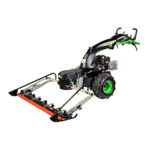
nMONTAGGIO GRUPPO BARRA FALCIANTE (Fig.5) La motofalce Ë provvista di un attacco che consente il collegamento facile
e rapido della barra falciante e di tutti gli altri accessori (spazzola, tosaerba, lama da neve, ecc.). A motore spento e con la macchina in posizione
orizzontale, inserire completamente il perno della barra (1), dopo averlo ingrassato con olio motore, nella sua sede (2).
-Montare la cinghia (3) prima sulla puleggia della macchina (puleggia piccola per la barra, la grande per gli accessori), poi su quella della barra
falciante (6).
-Agganciare le molle (4),che troverete nella busta accessori, nei rispettivi ganci (5).
-Assicurarsi che la cinghia (3) sia nella giusta posizione sulla puleggia che comanda la barra.
-Montare il cofano spartierba (7) ssandolo sull’antivibrante anteriore (8) poi sulla vite saldata. Mettere la rondella ed avvitare con il dado (9).
nMONTAGGIO LAMA FALCIANTE (Fig. 17 e 18) ATTENZIONE!! Per protezione, maneggiando la lama, usare sempre dei guanti robusti.
NB. Per facilitare il montaggio della lama falciante al corpo macchina si consiglia di eseguire il lavoro a banco ( un tavolo da lavoro).
Fig.17 e 18) Nella busta accessori si trova il blocchetto distanziale (5) che va leggermente ingrassato e posizionato sulla piastra comando barra (6).
Portare la lama nella giusta posizione e inlare il perno (7) nel blocchetto (5). Tra l’inizio della lettatura del perno (7) e il blocchetto distanziale (5)
deve esserci un minimo di gioco. Se ciò non si vericasse agire sul perno di registro (7). Fig.17) La lama falciante (1) viene avvitata al supporto barra
(2) per mezzo di quattro viti M8x20 (3) e altrettanti dadi (4) presenti nella busta accessori.
nMESSA IN MOTO (Fig.6) ATTENZIONE : La motofalce viene consegnata con il motore a 4 tempi senza olio. Il serbatoio ha una capacità di
circa 0,5 kg. e va riempito no al livello indicato.In ogni caso leggere sempre attentamente le istruzioni allegate relative al motore. Portare il manettino
dell’acceleratore (3) sulla posizione Start, quindi avviare il motore. Regolare il manettino in modo da raggiungere il regime di giri del motore desiderato.
Abbassare la leva rossa innesto attrezzi (4) PER FALCIARE e tirare la leva di comando sinistra (1) per avanzare cioè MARCIAAVANTI. Per innestare
la leva di comando destra (2) RETRO MARCIA è necessario rilasciare la leva marcia avanti (1). In caso di accidentale e imprevisto ostacolo, bisogna
lasciare immediatamente le due leve di comando (1-4) oppure la leva (2) retromarcia. A lavoro ultimato per spegnere il motore, portare il manettino
acceleratore (3) in posizione stop.
nREGISTRAZIONE E INNESTO BARRA FALCIANTE (Fig.7) Per aumentare la tensione della cinghia tra macchina ed attrezzo,

