2
condition will be occurred if the gap is greater than
35mm.
4. Remove the battery cover with the tamper switch
not being pressed on the Detector (test mode),
detach or close the magnet from the Detector, the
LED on the Detector will illuminate.
5. After proper installation and test, put the battery
cover back to the detector and the Detector enters
the normal mode.
Learning ID code
In order to communicate with the control panel, the
Detector and control panel need to be learned its
ID code with each other. By pressing the tamper
switch, located on the PCB of the Detector, more
than 3 seconds will emit the ID code to the control
panel instantly, subject to the control panel being
set at the ID code learning mode.
To emit the ID code to the control panel, proceed
with the following steps in sequence:
a. Press the learning key located on the PCB
more than 3 seconds until the LED of the
Detector flashes. It implies that the Detector
enters ID code learning mode.
b. A 30-second countdown will start. If the ID
code has been learned within 30 seconds by
the control panel successfully, the LED of the
Detector will be on shortly. If failure, the LED of
the Detector will flash three times rapidly.
c. If next ID code needs to be learned, start from
step a accordingly.
Clearing ID code
a. Press the tamper switch located on the PCB
more than 3 seconds until the LED of the
Detector flashes. It implies that the Detector
enters ID code learning mode.
b. Press the learning key again more than 6
seconds and release before 10 seconds. The
LED of the Detector will be on. The ID code
learned from the Control Panel has been
cleared.
TESTING THE DOOR/WINDOW CONTACTS
Ensure the system is in test mode.
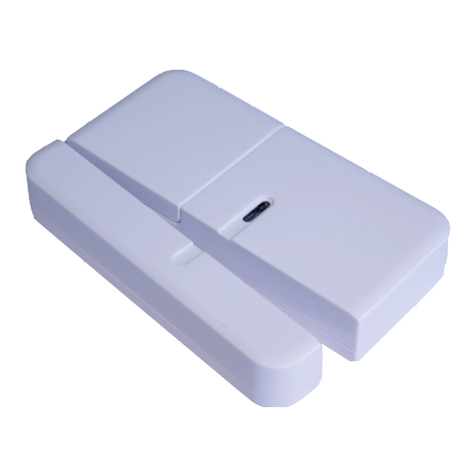
1. With the tamper switch not being pressed, the
Detector enters the test mode.
2. Open the door/window to detach the magnet from
the Detector. As the magnet is parted from the
detector, the LED will illuminate for approx. 1
second to indicate that the Detector has been
triggered.
3. If connected, operate the wired Magnetic Contact.
As the contact is opened the LED on the Detector
should illuminate for 1 second to indicate that it
has been triggered.
4. When the tamper switch is pressed, the Detector
enters the normal mode.
5. It is recommended that the operation of the
detector is also tested with the alarm in normal
operating mode to ensure that the Detector will
successfully trigger a FullAlarm condition.
Refer to your System Installation and Operating
Manual for further details on operating and testing the
system.
SPECIFICATIONS
RF Frequency
Distance
923(Taiwan USA)/868
(EU) MHz
150M @condition 1
Mechanical weight
Dimension (W x H x D)
23.6 g (without
battery)
31x70x11.5 mm
Battery CR2450
Battery life
620mAh
3 years @condition 2
Environment Operation Temperature
Humidity
-10 ~ 40° C
85%RH max
Hardware Magnetic gap(Open→Close)
Magnetic gap(Close→Open)
20 mm
35 mm
Condition 1. Send trigger signal to U-Net Controller like HSE01 or HSC04 in
any direction at open space
Condition 2 . At normal connect situation and trigger 10 times per day
*specifications are subject to change without prior notice.
FCCID: ZGXHSM01
Warning:
Do not dispose of electrical appliances as unsorted
municipal waste, use separate collection facilities.
Contact your local government for information
regarding the collection systems available.
If electrical appliances are disposed of in landfills or
dumps, hazardous substances can leak into the
groundwater and get into the food chain, damaging
your health and well-being.
