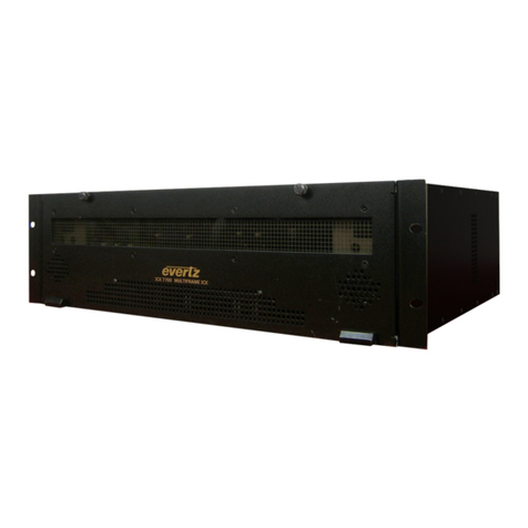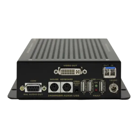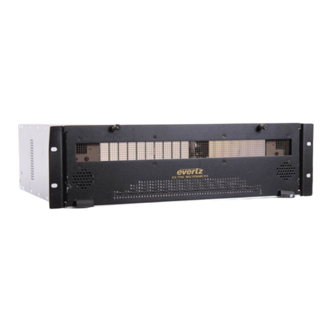
7700 Multi-Frame Manual
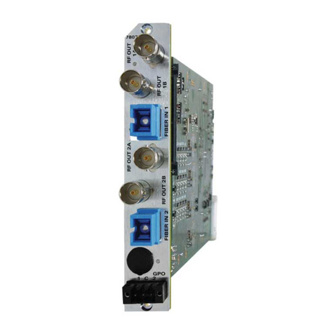
7708LR L-Band Fiber Receiver
Revision 0.3 7708LR
TABLE OF CONTENTS
1. OVERVIEW.........................................................................................................................................1
2. INSTALLATION..................................................................................................................................2
2.1. 7708LR CONNECTIONS...........................................................................................................3
2.2. CARE AND HANDLING OF OPTICAL FIBER..........................................................................3
2.2.1. Handling And Connecting Fibers ...................................................................................3
3. TECHNICAL SPECIFICATIONS........................................................................................................4
3.1.1. RF Output:......................................................................................................................4
3.1.2. Optical Input:..................................................................................................................4
3.1.3. Electrical:........................................................................................................................4
3.1.4. Physical:.........................................................................................................................4
4. STATUS INDICATORS AND DISPLAYS ..........................................................................................5
4.1.1. 7708LR Status Indicators...............................................................................................5
5. JUMPER POSITIONS ........................................................................................................................6
5.1. 7708LR JUMPERS....................................................................................................................6
5.2. SELECTING WHETHER LOCAL FAULTS WILL BE MONITORED
BY THE GLOBAL FRAME STATUS.........................................................................................6
5.3. CONFIGURING THE MODULE FOR FIRMWARE UPGRADES ..............................................7
5.4. FACTORY AND BDM JUMPERS .............................................................................................7
6. DOT-MATRIX DISPLAY.....................................................................................................................8
6.1. 7708LR CONTROLLED PARAMETERS ................................................................................10
6.1.1. Adjusting the Optical Power Alarm Thresholds............................................................10
6.1.2. Adjusting the RF Output Power Alarm and Squelch Thresholds..................................10
6.1.3. Selecting the Output Gain Mode..................................................................................11
6.1.4. Adjusting the RF Output Gain......................................................................................11
6.1.5. Adjusting the AGC Target Level...................................................................................11
6.1.6. Enabling/Disabling Squelch Mode ...............................................................................12
6.1.7. Setting the Card Edge Display Orientation...................................................................12
6.1.8. Resetting Factory Defaults...........................................................................................12
6.2. TRANSMITTER CONTROLLABLE PARAMETERS...............................................................13
6.2.1. Adjusting the RF Input Power Alarm Thresholds .........................................................13
6.2.2. Adjusting the Internal Transmitter Temperature Alarm Thresholds..............................13
6.2.3. Adjusting the Input Voltage Alarm Thresholds.............................................................13
6.3. 7708LR MONITORED CONDITIONS AND PARAMETERS...................................................14
6.3.1. Displaying the Input Optical Power..............................................................................14


