manuals.online logo
Brands
  1. Home
  2. •
  3. Brands
  4. •
  5. HEIDENHAIN
  6. •
  7. Control System
  8. •
  9. HEIDENHAIN TNC 407 User manual

HEIDENHAIN TNC 407 User manual

This manual suits for next models

9

Other HEIDENHAIN Control System manuals

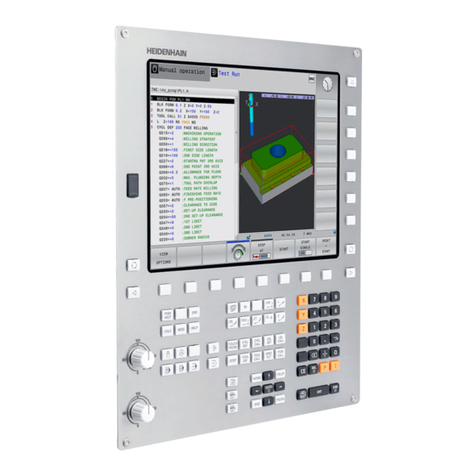
HEIDENHAIN TNC 320 User manual

HEIDENHAIN

HEIDENHAIN TNC 320 User manual

HEIDENHAIN ITNC 530 - CONVERSATIONAL PROGRAMMING User manual

HEIDENHAIN

HEIDENHAIN ITNC 530 - CONVERSATIONAL PROGRAMMING User manual

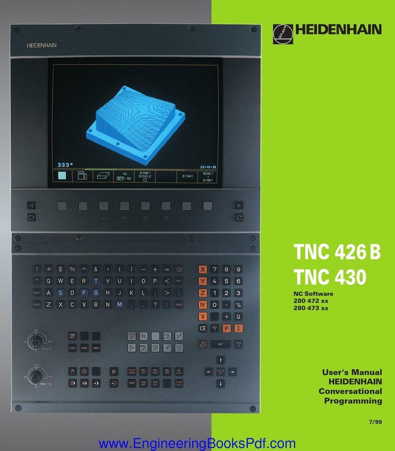
HEIDENHAIN TNC 426 B User manual

HEIDENHAIN

HEIDENHAIN TNC 426 B User manual

HEIDENHAIN TNC 620 User manual

HEIDENHAIN

HEIDENHAIN TNC 620 User manual

HEIDENHAIN TNC 620 Programming Station User manual

HEIDENHAIN

HEIDENHAIN TNC 620 Programming Station User manual

HEIDENHAIN TNC 150 B User manual

HEIDENHAIN

HEIDENHAIN TNC 150 B User manual

HEIDENHAIN TNC 150 B User manual

HEIDENHAIN

HEIDENHAIN TNC 150 B User manual

HEIDENHAIN MANUALPLUS 620 User manual

HEIDENHAIN

HEIDENHAIN MANUALPLUS 620 User manual

HEIDENHAIN ECN 413 2C User manual

HEIDENHAIN

HEIDENHAIN ECN 413 2C User manual

HEIDENHAIN TNC 370 D Manual

HEIDENHAIN

HEIDENHAIN TNC 370 D Manual

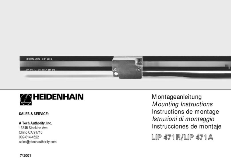
HEIDENHAIN LIP 471R User manual

HEIDENHAIN

HEIDENHAIN LIP 471R User manual

HEIDENHAIN TNC 620 User manual

HEIDENHAIN

HEIDENHAIN TNC 620 User manual

HEIDENHAIN ND 780 User manual

HEIDENHAIN

HEIDENHAIN ND 780 User manual

HEIDENHAIN POSITIP 880 User manual

HEIDENHAIN

HEIDENHAIN POSITIP 880 User manual

HEIDENHAIN TNC151B Operating instructions

HEIDENHAIN

HEIDENHAIN TNC151B Operating instructions

HEIDENHAIN AK ECM 2410 User manual

HEIDENHAIN

HEIDENHAIN AK ECM 2410 User manual

HEIDENHAIN ITNC 530 - CONVERSATIONAL PROGRAMMING User manual

HEIDENHAIN

HEIDENHAIN ITNC 530 - CONVERSATIONAL PROGRAMMING User manual

HEIDENHAIN ITNC 530 - CONVERSATIONAL PROGRAMMING User manual

HEIDENHAIN

HEIDENHAIN ITNC 530 - CONVERSATIONAL PROGRAMMING User manual

HEIDENHAIN ITNC 530 - CONVERSATIONAL PROGRAMMING User manual

HEIDENHAIN

HEIDENHAIN ITNC 530 - CONVERSATIONAL PROGRAMMING User manual

HEIDENHAIN CNC PILOT 640 User manual

HEIDENHAIN

HEIDENHAIN CNC PILOT 640 User manual

HEIDENHAIN iTNC 530 HSCI User manual

HEIDENHAIN

HEIDENHAIN iTNC 530 HSCI User manual

HEIDENHAIN AK LIC 413 User manual

HEIDENHAIN

HEIDENHAIN AK LIC 413 User manual

HEIDENHAIN TNC 320 User manual

HEIDENHAIN

HEIDENHAIN TNC 320 User manual

HEIDENHAIN LIF 181 R User manual

HEIDENHAIN

HEIDENHAIN LIF 181 R User manual

Popular Control System manuals by other brands

Comunello BORDER 400 Installation and user manual

Comunello

Comunello BORDER 400 Installation and user manual

Verlinde EUROBLOC Variator VTN Service manual

Verlinde

Verlinde EUROBLOC Variator VTN Service manual

Diginet DGOZ-TCSW-LR35 installation guide

Diginet

Diginet DGOZ-TCSW-LR35 installation guide

VADDIO ControlVIEW Xtreme manual

VADDIO

VADDIO ControlVIEW Xtreme manual

Duke HSHU 13 SERIES Installation and operation manual

Duke

Duke HSHU 13 SERIES Installation and operation manual

AIRTRONICS Blazer Sport manual

AIRTRONICS

AIRTRONICS Blazer Sport manual

Pentair Pool Products Compool Installation and user guide

Pentair Pool Products

Pentair Pool Products Compool Installation and user guide

ComfortNET CTK04 manual

ComfortNET

ComfortNET CTK04 manual

CAME G3000 installation manual

CAME

CAME G3000 installation manual

Idemia MorphoAccess VP MD installation guide

Idemia

Idemia MorphoAccess VP MD installation guide

Doosan DVF Series Operation user's manual

Doosan

Doosan DVF Series Operation user's manual

Axis P1445-LE-3 user manual

Axis

Axis P1445-LE-3 user manual

CNC-Step High-Z T-Series operating instructions

CNC-Step

CNC-Step High-Z T-Series operating instructions

Honeywell KAP 140 Maintenance manual

Honeywell

Honeywell KAP 140 Maintenance manual

Honeywell vk41 series Handbook

Honeywell

Honeywell vk41 series Handbook

Cypress HHR-3160 product manual

Cypress

Cypress HHR-3160 product manual

Zonex GEN II -VVT Installation and application manual

Zonex

Zonex GEN II -VVT Installation and application manual

Altronics K 9650 quick start guide

Altronics

Altronics K 9650 quick start guide

manuals.online logo
manuals.online logoBrands
  • About & Mission
  • Contact us
  • Privacy Policy
  • Terms and Conditions

Copyright 2025 Manuals.Online. All Rights Reserved.

User's Manual
ISO Programming
TNC 426
TNC 425
TNC 415
B
TNC 407
Oktober 1995
Controls on the visual display unit
Toggle display between machining and
programming modes
Split screen layout
Soft keys for selecting functions in screen
Shift keys for the soft keys
Brightness, contrast
Typewriter keyboard for entering letters and symbols
File names/
comments
ISO
programming
Machine operating modes
MANUAL OPERATION
EL. HANDWHEEL
POSITIONING WITH MDI
PROGRAM RUN/SINGLE BLOCK
PROGRAM RUN/FULL SEQUENCE
Programming modes
PROGRAMMING AND EDITING
TEST RUN
Program and file management
Select programs and files
Delete programs and files
(not on TNC 426)
Enter program call in a program
External data transfer
(not on TNC 426)
MODfunctions
Pocket calculator
(TNC 426 only)
Moving the cursor and going directly to
blocks, cycles and parameter functions
Move the cursor (highlight)
Go directly to blocks, cycles and
parameter functions
Override control knobs
Feed rate Spindle speed
Controls on the TNC 426, TNC 425, TNC 415 B and
TNC 407
...
...
Q
R
Y
W
E
T
G F S T
M
GRAPHICS
TEXT
SPLIT
SCREEN
CR
CT
CHF
RND
APPR
DEP
L
CC
C
R
+
R
TOOL
CALL
TOOL
DEF
R-
L
Programming path movements
(conversational programming only)
Approach/depart contour
Straight line
Circle center/pole for polar coordinates
Circle with center
Circle with radius
Tangential circle
Chamfer
Corner rounding
Tool functions
(conversational programming only)
Enter or call tool length and radius
Activate tool radius compensation
(not on TNC 426)
Cycles, subprograms and program section repeats
(conversational programming only)
Define and call cycles
Enter and call labels for subprogramming
and program section repeats
Enter program stop in a program
Enter touch probe functions in a program
Coordinate axes and numbers, editing
Select coordinate axes or enter
them into a program
Numbers
Decimal point
Arithmetic sign
Polar coordinates
Incremental dimensions
Q parameters for part families or
mathematicalfunctions
Capture actual position
Skip dialog questions, delete words
Confirm entry and resume dialog
End block
Clear numerical entry or TNC message
Abort dialog, delete program sections
+/
NO
ENT
Q
P
CE
DEL
9
V
0
MOD
PGM
CALL
GOTO
1
50
0
50
100
S %
...
CL
PGM
EXT
CYCL
CALL
LBL
SET
LBL
CALL
STOP
TOUCH
PROBE
CYCL
DEF
PGM
MGT
PGM
NAME
CALC
1
50
0
50
100
F %
TNC Guideline
From the workpiece drawing to
program-controlled machining
or
or
or
or
Step Task TNC operating Section in
mode manual
Preparation
1 Select tools —— ——
2 Set workpiece datum for
coordinate system —— ——
3 Determine spindle speeds
and feed rates —— ——
4 Switch on the machine —— 1.3
5 Cross over reference marks 1.3, 2.1
6 Clamp workpiece —— ——
7 Set datum /
Reset position display ...
7a ... with 3D touch probe 2.5
7b ... without
3D touch probe 2.3
Entering and testing part programs
8 Enter part program or download
over external data interface 5 to 8, 9
9 Test part program for errors
3.1
10 Test run: Run the program
block by block without tool 3.2
11 Optimize the part program
(if necessary) 5 to 8
Machining the workpiece
12 Insert tool and run program 3.2
TNC 426/TNC 425/TNC 415 B/TNC 407
How to use this manual
This manual describes functions and features available on TNCs as of the following NC software numbers:
NC Software No.
TNC 407 280 580 04
TNC 415 B, TNC 425 280 540 04
TNC 415 F, TNC 425 E 280 560 04
TNC 426 CA, TNC 426 PA 280 462 01
TNC 426 CE, TNC 426 PE 280 482 01
The suffixes E and F indicate export versions of the TNC.
The export versions TNC 415 F, TNC 425 E, TNC 426 CE, and
TNC 426 PE have the following limitations:
• Input and machining accuracy are limited to 1 µm
• Simultaneous linear movement in up to 4 axes
Some of the functions described in this manual are not available on all
TNCs. These functions are marked with symbols:
Function not available on the TNC 407
Function not available on the TNC 415
Function not available on the TNC 425
Function not available on the TNC 426
The machine manufacturer adapts the features offered by the TNC to the
capabilities of the specific machine tool by setting machine parameters.
This means that not every machine tool will have all of the functions
described in this manual.
Some of the TNC functions which are not available on every machine are:
• Probe functions for the 3D touch probe
• Digitizing option
(conversational programming only)
• Measuring tools with the TT 120 touch probe
(conversational programming only)
• Rigid tapping
• Re-approaching a contour after an interruption
Your machine manual provides more detailed information. If you think a
function may be unavailable because of a defect, please contact the
machine tool builder.
Many machine manufacturers and HEIDENHAIN offer programming
courses for the TNCs. We recommend these courses as an effective way
of improving your programming skill and sharing information and ideas with
other TNC users.
407
415
425
426
TNC 426/TNC 425/TNC 415 B/TNC 407
This manual is intended both for the TNC beginner and the TNC expert.
The TNC beginner can use it as a step-by-step workbook. The manual
begins with an explanation of the basics of numerical control (NC) and
provides a glimpse into their application in the TNC. It then introduces
the technique of conversational programming. All of the examples can
be practiced directly on the TNC. Each function is explained thoroughly
when it is used for the first time.
The TNC beginner should work through this manual completely from
beginning to end to ensure that he is capable of fully exploiting the
features of this powerful tool.
The TNC expert can use the manual as a comprehensive review and
reference work. The table of contents and numerous cross references
help him quickly find the topics and information he needs. Easy-to-read
dialog flowcharts show him how to enter data for the desired function.
The dialog flowcharts aid the beginner by providing a description of the
function of each key in a box to its right. If the user already knows the
keys, he can concentrate on the illustrated input overview at the left of
the flowchart. The TNC dialog messages are represented in shaded
boxes above the answering input sequence.
TNC 426/TNC 425/TNC 415 B/TNC 407
Layout of the dialog flowcharts
Dialog initiation key
DIALOG PROMPT (ON THE TNC SCREEN)
Here the manual explains the function of the keys.
NEXT DIALOG PROMPT
Function of the key
Function of the alternative key
The trail of points means that:
• the dialog is not completely illustrated, or
• the dialog continues on the next page.
Abbreviated dialog flowcharts
In abbreviated flowcharts an arrow (➤) is used to indicate new entries or
worksteps.
e.g.
Press this key
Or this key
Answer the prompt with
these keys
.
.
.
+/
A broken line indicates that
either the key above it or
below it can be pressed.
G
83
ENT
83
1
2
3
4
5
6
7
8
9
10
11
Contents User's Manual TNC 407, TNC 415 B, TNC 425, TNC 426
(280 5x0-xx, 280 462-xx)
ISO Programming
Introduction
Manual Operation and Setup
Test Run and Program Run
Programming
Programming Tool Movements
Subprograms and Program Section Repeats
Programming with Q Parameters
Cycles
External Data Transfer
MOD-Functions
Tabels, Overviews and Diagrams
TNC 426/TNC 425/TNC 415 B/TNC 407
1 Introduction
1.1 The TNC 400 Series ............................................................................1-2
Keyboard........................................................................................................................ 1-4
Visual display unit .......................................................................................................... 1-5
TNC Accessories ........................................................................................................... 1-9
1.2 Fundamentals of NC.........................................................................1-10
Introduction .................................................................................................................. 1-10
What is NC? ................................................................................................................. 1-10
The part program .........................................................................................................1-10
Programming ............................................................................................................... 1-10
Reference system ........................................................................................................ 1-11
Cartesian coordinate system ....................................................................................... 1-11
Additional axes............................................................................................................. 1-12
Polar coordinates .........................................................................................................1-12
Setting the pole ............................................................................................................ 1-13
Datumsetting ............................................................................................................... 1-13
Absolute workpiece positions.......................................................................................1-15
Incremental workpiece positions ..................................................................................1-15
Programming tool movements ..................................................................................... 1-18
Position encoders ........................................................................................................ 1-18
Reference marks......................................................................................................... 1-18
1.3 Switch-On ..........................................................................................1-19
1.4 Graphics and Status Displays .........................................................1-20
Graphics during program run ....................................................................................... 1-20
Plan view...................................................................................................................... 1-21
Projection in 3 planes................................................................................................... 1-22
Cursor position during projection in 3 planes ............................................................... 1-23
3D view ........................................................................................................................ 1-23
Magnifying details ........................................................................................................ 1-25
Repeating graphic simulation....................................................................................... 1-26
Measuring the machining time ..................................................................................... 1-26
Status displays ............................................................................................................. 1-27
Additional status displays.............................................................................................1-27
1.5 File Management on the TNC 426 ...................................................1-30
Data security ................................................................................................................ 1-30
Calling the file manager ............................................................................................... 1-31
Functions for file management..................................................................................... 1-35
Selecting file types .......................................................................................................1-36
To copy individual files ................................................................................................. 1-36
To copy several files into another directory ................................................................. 1-37
To erase a file ..............................................................................................................1-38
To rename a file ........................................................................................................... 1-38
To protect a file ............................................................................................................ 1-38
To cancel file protection ...............................................................................................1-38
To convert a file ........................................................................................................... 1-39
TNC 426/TNC 425/TNC 415 B/TNC 407
1.6 File Management on the TNC 425, TNC 415 B and TNC 407 ........1-40
File directory ................................................................................................................ 1-40
File status.....................................................................................................................1-41
Selecting a file.............................................................................................................. 1-41
To copy a file................................................................................................................ 1-42
To erase a file ..............................................................................................................1-42
To rename a file ........................................................................................................... 1-42
To protect a file ............................................................................................................ 1-42
To cancel file protection ...............................................................................................1-42
To convert a file ........................................................................................................... 1-43
File management for files on external data media ....................................................... 1-43
TNC 426/TNC 425/TNC 415 B/TNC 407
2 Manual Operation and Setup
2.1 Moving the Machine Axes...................................................................2-2
Traversing with the machine axis direction buttons................................................... 2-2
Traversing with an electronic handwheel .................................................................. 2-3
Using the HR 330 electronic handwheel ................................................................... 2-3
Incremental jog positioning........................................................................................ 2-4
Positioning with manual data input (MDI) .................................................................. 2-4
2.2 Spindle Speed S, Feed Rate F and Miscellaneous Functions M.....2-5
To enter the spindle speed S .................................................................................... 2-5
To change the spindle speed S ................................................................................. 2-5
To change the feed rate F .........................................................................................2-6
To enter a miscellaneous function M......................................................................... 2-6
2.3 Setting the Datum Without a 3D Touch Probe ..................................2-7
Setting the datum in the tool axis .............................................................................. 2-7
To set the datum in the working plane ...................................................................... 2-8
2.4 3D Touch Probes .................................................................................2-9
3D Touch probe applications..................................................................................... 2-9
To select the touch probe functions .......................................................................... 2-9
Calibrating the 3D touch probe................................................................................ 2-10
Compensating workpiece misalignment .................................................................. 2-12
2.5 Setting the Datum with a 3D Touch Probe ......................................2-14
To set the datum in an axis ..................................................................................... 2-14
Corner as datum ......................................................................................................2-15
Circle center as datum ............................................................................................ 2-17
2.6 Measuring with a 3D Touch Probe ...................................................2-20
To find the coordinates of a position on an aligned workpiece................................ 2-20
Finding the coordinates of a corner in the working plane ........................................ 2-20
Measuring workpiece dimensions ........................................................................... 2-21
Measuring angles .................................................................................................... 2-22
2.7 Tilting the Working Plane .................................................................2-24
Traversing reference points with tilted axes ............................................................ 2-25
Setting the datum in a tilted coordinate system....................................................... 2-25
Position display in the tilted system......................................................................... 2-25
Limitations on working with the tilting function ........................................................ 2-25
To activate manual tilting......................................................................................... 2-26