Viale Vicenza, 14
36063 Marostica VI - Italy
www.vimar.com
49401643A0 01 2212
03824
BY-ALARM PLUS
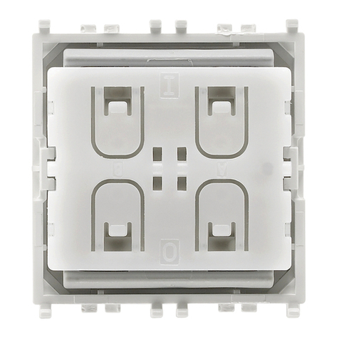
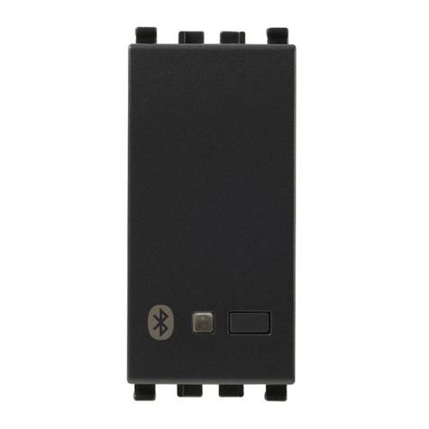
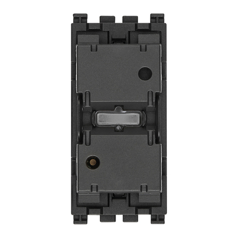
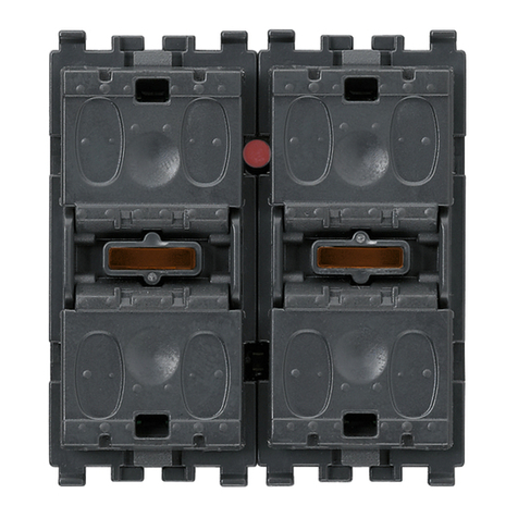
Inseritore/parzializzatore By-alarm Plus, 4 LED di segnalazione associabili a
scenari di inserimento/azionamento.
L’inseritore è il dispositivo che attiva e disattiva l’impianto (completamente o le zone parzializzate
associate) dopo aver riconosciuto il codice emesso dalle chiavi a transponder art. 03825.G o
03825.Y. Consente anche di attivare una macro (automazione) associata alla chiave in uso.
E' provvisto di quattro led che visualizzano la tipologia delle operazioni effettuate sull'impianto
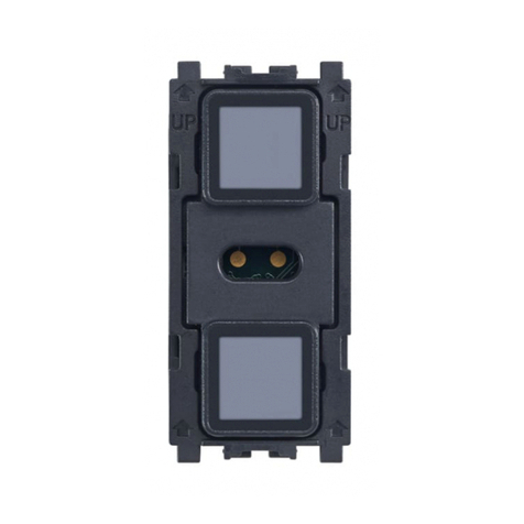
(attivazione, disattivazione, ecc.). L'installazione deve essere completata agganciando al dispo-
sitivo gli appositi adattatori da incasso Linea, Eikon, Arké e Plana che prevedono un montaggio
tipo "keystone".
COLLEGAMENTI
Il collegamento con la centrale va effettuato con un cavo schermato a 4 (o più) fili.
Attenzione: La calza va collegata ad uno dei morsetti di massa (o GND) solo dal lato della
centrale e deve seguire tutto il BUS senza essere collegata a massa in altri punti.
Il collegamento della scheda va effettuato sui morsetti “+ D S -” della centrale.
SEGNALAZIONI DEI LED
Il software By-alarm Plus Manager consente, per ciascun led del dispositivo, di configurare i coman-
di da attivare sulle aree mediante le chiavi a transponder (ad esempio inserimento o disinserimento)
e ottenere informazioni sullo stato delle aree stesse. E' possibile associare al led anche altri comandi
quali tacitazione della sirena, interrompere chiamate, disattivare l'autoinserimento, cancellare la
memoria allarmi.
Importante:
• Le informazioni visualizzate dai led sono riferite ad una o più aree effettivamente associate
sull’inseritore.
• Se il sistema è stato impostato per essere conforme alle normative sugli impianti antintrusione,
lo stato di inserimento delle aree NON è mai visualizzato sui led degli inseritori (questo impedi-
sce agli estranei di conoscere lo stato dell’impianto).
Nella tabella sotto è indicato il significato dei led durante il normale funzionamento.
Modalità alternativa del lettore di segnalazione stato aree = disabilitata
Led Acceso fisso Lampeggio lento Lampeggio veloce
Verde - -
Allarme o sabotaggio in
corso su aree
Blu Zone aperte su aree -
Giallo - -
Rosso Aree inserite Aree in memoria di allarme
o sabotaggio
Modalità alternativa del lettore di segnalazione stato aree = abilitata
Led Acceso fisso Lampeggio lento Lampeggio veloce
Verde Tutte le aree associate
allo specifico led sono
inserite nella modalità
configurata nel software
By-alarm Plus Manager.
Almeno una delle aree
associate allo specifico
led, configurate mediante
By-alarm Plus Manager,
risulta essere in memoria
allarme o sabotaggio.
Almeno una delle aree
associate allo specifico
led, configurate mediante
By-alarm Plus Manager,
risulta in stato di allarme
o sabotaggio.
Blu
Giallo
Rosso
INSTALLAZIONE
1. Effettuare i collegamenti.
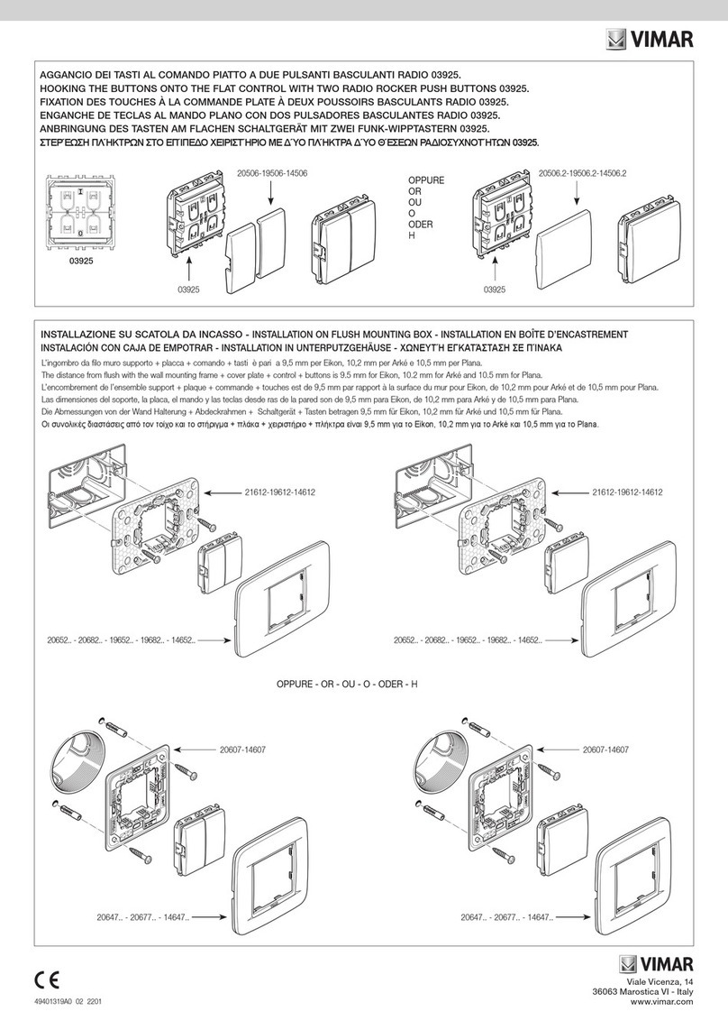
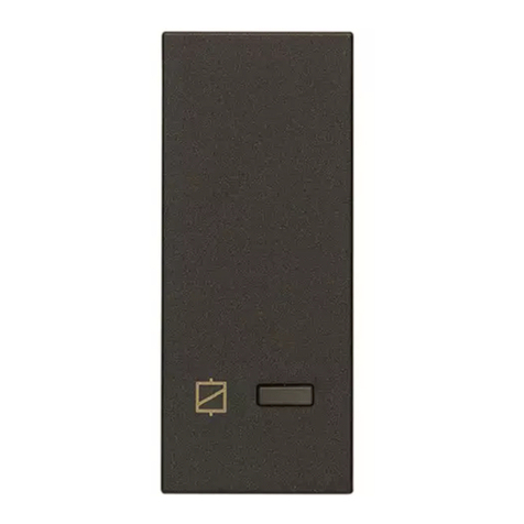
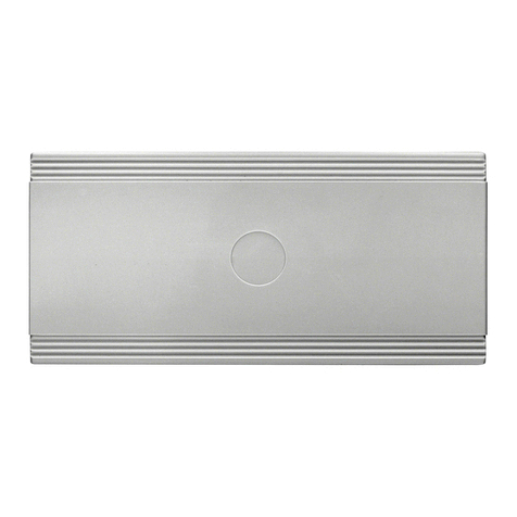
2. Montare il coperchio sul dispositivo (art. 31528.x per Linea, art. 20477 per Eikon, art.19477
per Arké, art. 19477 per Plana) come illustrato nella figura INSTALLAZIONE.
3. Agganciare l'inseritore al supporto.
4. Effettuare la procedura di configurazione del dispositivo.
CONFIGURAZIONE
Per tutti i dettagli si vedano i manuali di installazione del sistema By-Alarm Plus e del software
By-alarm Plus Manager.
REGOLE DI INSTALLAZIONE
• L’installazione e la configurazione devono essere effettuate da personale qualificato con l’os-
servanza delle disposizioni regolanti l’installazione del materiale elettrico in vigore nel paese
dove i prodotti sono installati.
• Il dispositivo deve essere installato su scatole dedicate SELV oppure in scatole con separatori
divisori rispetto ad eventuali parti in tensione a 230 V~.
• Il dispositivo va completato con gli artt. 31528 per Linea, 20477 per Eikon, 19477 per Arké e
14977 per Plana.
CARATTERISTICHE
• Tensione di alimentazione dal bus: da 9 a 15 V
• Corrente assorbita
- senza chiave: 20 mA
- con chiave: 50 mA
• Range di frequenza: 119-128,6 kHz
• Max intensità di campo H: 66dBµA/m a 10 m
• Temperatura di funzionamento: da -10 a +40 °C
• Umidità relativa: ≤75% senza condensazione
• Grado di sicurezza: 3
• Classe d’isolamento: II
• Dimensioni (L x A x P): 42 x 51 x 20 mm
• Peso: 19 g
CONFORMITA' NORMATIVA.
Direttiva RED. Direttiva RoHS.
Norme EN 62368-1, EN 50130-4, EN 50130-5, EN 55032, EN 50131-3, EN 301 489-3, EN 300
330, EN 62479, EN IEC 63000.
Vimar SpA dichiara che l’apparecchiatura radio è conforme alla direttiva 2014/53/UE. Il testo
completo della dichiarazione di conformità UE è disponibile nella scheda di prodotto al seguente
indirizzo Internet: www.vimar.com.
Regolamento REACh (UE) n. 1907/2006 – art.33. Il prodotto potrebbe contenere tracce di
piombo.
RAEE - Informazione agli utilizzatori
Il simbolo del cassonetto barrato riportato sull’apparecchiatura o sulla sua confezione indica che il prodotto alla fine della
propria vita utile deve essere raccolto separatamente dagli altri rifiuti. L’utente dovrà, pertanto, conferire l’apparecchiatura
giunta a fine vita agli idonei centri comunali di raccolta differenziata dei rifiuti elettrotecnici ed elettronici. In alternativa alla
gestione autonoma, è possibile consegnare gratuitamente l’apparecchiatura che si desidera smaltire al distributore, al mo-
mento dell’acquisto di una nuova apparecchiatura di tipo equivalente. Presso i distributori di prodotti elettronici con superficie
di vendita di almeno 400 m2è inoltre possibile consegnare gratuitamente, senza obbligo di acquisto, i prodotti elettronici da
smaltire con dimensioni inferiori a 25 cm. L’adeguata raccolta differenziata per l’avvio successivo dell’apparecchiatura dismes-
sa al riciclaggio, al trattamento e allo smaltimento ambientalmente compatibile contribuisce ad evitare possibili effetti negativi
sull’ambiente e sulla salute e favorisce il reimpiego e/o riciclo dei materiali di cui è composta l’apparecchiatura.
By-alarm Plus actuator/partitioner, 4 indicator LEDs can be associated with
activation/operation scenarios.
The actuator is the device that turns the system on and off (completely or the associated
partitioned zones) after recognising the code emitted by the transponder keys art. 03825.G or
03825.Y. It can also be used to activate a macro (automation) associated with the key being
used. It has four LEDS to display the system operation type (activation, deactivation, etc.). To
complete the installation, attach the special Linea, Eikon, Arké or Plana flush mounting adapter
to the device for "keystone" mounting.
CONNECTIONS
Connect it to the control unit with a 4-wire (or more) shielded cable.
Caution: Connect the shield to one of the earth (or GND) terminals at the control unit end
only, and ensure that it follows the entire BUS without being connected to earth at any other
point.
Connect the board to the “+ D S -” terminals on the control unit.
LED INDICATIONS
For each device LED, the By-alarm Plus Manager software can configure the commands to be
activated in the areas by the transponder keys (e.g. activation or deactivation) and obtain area
status information. The LEDs can be associated with other commands, such as silencing the siren,
ending calls, deactivating self-start or deleting the alarm memory.
Important:
• The information displayed by the LEDs refers to one or more areas associated with the
actuator.
• If the system has been set up to comply with the anti-tampering regulations, the actuator
LEDs never display the area activation status (so that unauthorised persons are not aware of
the system status).
The table below shows the LED meanings during normal operation.
Alternative mode on area status indication reader = disabled
LED On continuously Slow flashing Fast flashing
Green - -
Alarm or tampering
currently taking place in
an area
Blue Open zone in an area -
Yellow - -
Red Areas activated Area in alarm memory or
tampering
Alternative mode on area status indication reader = enabled
LED On continuously Slow flashing Fast flashing
Green All areas associated
with the specific LED
are activated in the
mode configured in the
By-alarm Plus Manager
software.
At least one of the areas
associated with the spe-
cific LED, as configured
with the By-alarm Plus
Manager software, is in
the alarm or tampering
memory.
At least one of the areas
associated with the spe-
cific LED, as configured
with the By-alarm Plus
Manager software, is in
the alarm or tampering
state.
Blue
Yellow
Red
INSTALLATION
1. Make the connections.
2. Fit the cover on the device (art. 31528.x for Linea, art. 20477 for Eikon, art.19477 for Arké,
art. 19477 for Plana) as shown in the INSTALLATION figure.
3. Attach the actuator to the mounting frame.
4. Perform the device configuration procedure.

