Excelitas Technologies X-Cite XLED1 User manual
www.excelitas.com
Guide to Trigger X-Cite®XLED1 with
the optiMOS sCMOS camera
Introduction
Hardware triggering uses high-speed Transistor-Transistor Logic
(TTL) voltage pulses to synchronize multiple devices (camera,
light source, microscope stage, etc.) in an imaging system. This
hardware-based synchronization is often a necessary mode of
operation for high-speed experiments including patch clamp
electrophysiology, particle tracking and Ca2+ imaging.
Triggering a traditional arc lamp system involves opening and
closing of a physical shutter to allow or block light going through
a microscope system. High speed pulsing of arc lamps requires
specialized lamps and high-voltage power supplies, which lack
stability. LEDs on the other hand can be switched ON and OFF
almost instantaneously. This allows them to respond quickly in a
triggering situation. When voltage is sent to the unit, it switches
ON and when the voltage is stopped, it switches OFF without any
delay.
A particularly useful feature of the QImaging optiMOS for
synchronizing with LED sources is the "All Rows" exposure
mode. This mode allows the optiMOS to run in a high-speed
rolling shutter mode while avoiding rolling shutter artifacts,
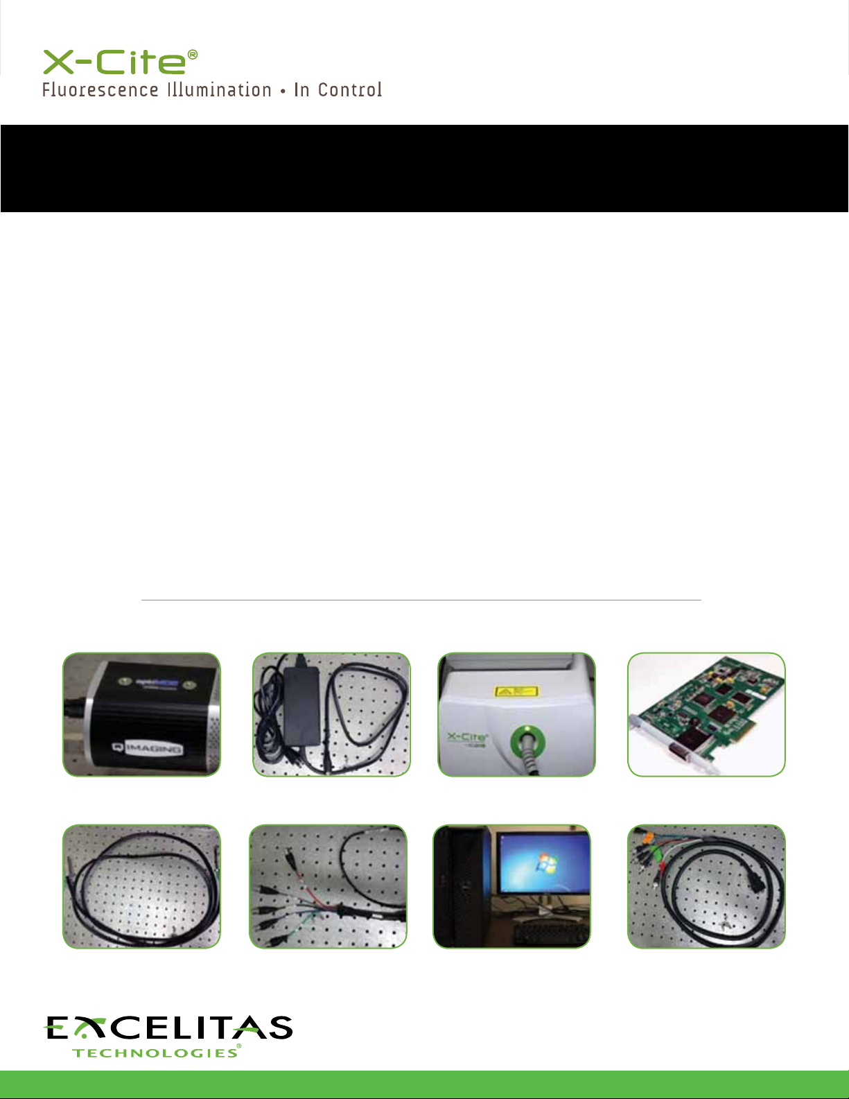
Required Items:
such as uneven illumination across all the rows of an image
or mixing of multiple color channels in a single image. These
artifacts occur as a result of each row beginning exposure at a
slightly later time than the previous row due to the mechanism
of rolling shutter readout. All Rows mode avoids these artifacts
by using the Expose Out TTL voltage pulses to trigger the
light source to illuminate only when all the optiMOS’ rows are
exposing at the same instant in time. For this mode to function
properly, especially at high frame rates, precise synchronization
between the camera and a high speed light source is required.
It is essential that the time required to turn the light on and off
is very small relative to the exposure time of the camera. New
high speed light sources such as the X-Cite®XLED1 from Excelitas
Technologies are capable of shuttering the light on the order
of microseconds, making it possible to both achieve a uniform
global illumination in this All Rows Mode as well as rapidly switch
between multiple excitation wavelengths.
This guide will demonstrate how to use hardware triggering with
the optiMOS sCMOS camera from QImaging and the X-Cite
XLED1 fluorescence light source from Excelitas Technologies.
QImaging optiMOS
sCMOS Camera
optiMOS Data Cable
optiMOS Power Supply
optiMOS Trigger Cable
X-Cite XLED1 Light Source
X-Cite XLED1 Light Source
Trigger Cable
Computer
optiMOS PCIe PC Interface card

2 www.ldgi.com | OmniCure® Application Note |
Mar. 2014
Setup:
Diagram:
optiMOS
Data Cable
Power Supply
optiMOS
Trigger Cable
X-Cite XLED1
Light Source
X-Cite XLED1 Light
Source Trigger Cable
Computer
High PCIe Card
Microscope
The X-Cite XLED1 light source trigger cable splits into 5 separate
lines. The blue, green, red, and white lines each correspond to one
of 4 LEDs in the XLED1 light source, each with a different color/
wavelength range. Each of the 4 different color LEDs can be used
to excite a different fluorophore. Sending a TTL voltage pulse into
a line in the XLED1 trigger cable causes the corresponding LED to
switch on when the TTL pulse voltage is high and off when the TTL
pulse voltage is low. The black line in the XLED1 trigger cable is a
“global” line which triggers all lines/LEDs simultaneously. The light
source must be set up for triggered operation. This procedure will
be described in the next section.
For single color triggering, attach optiMOS trigger cable “Expose
Out” line to the line on the XLED1 trigger cable corresponding
to the specific LED color to be
triggered. With this configuration,
the optiMOS’ Expose Out line will
produce a high TTL pulse while
the optiMOS is exposing, causing
the specific color LED in the XLED1
light source to turn on. The Expose
Out line will produce a low TTL
signal at the end of exposure,
causing the LED in the light source to turn off.
3. Set up external triggering on the XLED1 Display Module touchscreen
or software panel by first pressing the Trigger button.
Note: Even if the button looks greyed out and is labelled "triggered",
it still needs to be pressed.
4. Select the color channel to be triggered and cycle through the trigger
modes using “Change Trigger” until triggering by an “External Source”
(Ext) is chosen. Return to LED screen.
2. Connect the XLED1 trigger
cable to the “Trigger Input”
connector on the back of
the XLED1 controller, as
shown below.
Connection Instructions
1. Connect the components as
diagrammed above. A close-
up of the connectors on the
back of the optiMOS is
shown below.

Software Setup
Install the latest version of the PVCAM driver, version 3.1.8 or
higher. This can be found on the thumb drive included with the
optiMOS or from the Software section of the QImaging website.
Install the high-speed PCI express card with Serial Light connector
into an open PCIe slot with 4 channels or higher. Close the
computer. Connect the data cable from the optiMOS to the high
speed PCI express card. Turn on the computer and the optiMOS.
optiMOS Triggering Modes
The optiMOS should be run in Clear Pre-Sequence mode for the
highest speed performance. There are also three available Expose
Out modes as well as three available Trigger modes. The Expose Out
modes select the TTL pulse behavior of the Expose Out line on the
optiMOS trigger cable. The three modes are First Row, Any Row, and
All Rows. The All Rows behavior is diagrammed below:
• AllRows—GlobalIlluminationMode.ExposeOut
signal voltage is high only while all rows are exposing,
i.e. from when the last row begins exposing until the
first row ends exposing.
These settings can be added to the Micro-manager front panel
forquickavailabilitybyclickingthe“+”buttonnextto“Group”.
Alternatively, these settings can be adjusted under the Device/
Property Browser available under “Tools”.
All Rows (Global Illumination Mode) Vertical axis is Row
number, Horizontal axis is Time:
Frame
Exposure
Expose

2260 Argentia Road
Mississauga, Ontario
L5N 6H7 CANADA
Telephone: +1 905 821-2600
Toll Free (USA and CAN): +1 800 668-8752
Fax: +1 905 821-2055
www.excelitas.com
For a complete listing of our global offices, visit www.excelitas.com/locations
© 2015 Excelitas Canada Inc. X-Cite is a registered trademark of Excelitas Canada Inc. The Excelitas logo and design are registered trademarks of Excelitas Technologies Corp. All other trademarks are the property of their respective owners, and neither
Excelitas Technologies Corp., its affiliates or subsidiaries, or any of their respective products, are endorsed or sponsored by or affiliated in any way whatsoever with those organizations whose trademarks and/or logos may be mentioned herein for reference
purposes. Excelitas Canada Inc. reserves the right to change this document at any time without notice and disclaims liability for editorial, pictorial or typographical errors.
03.2015
3. External triggering in the XLED1 Display Module touchscreen or
software panel can be set up similarly to the single color triggering
setup. First, press the Trigger button.
Note: Even if the button looks greyed out and is labelled "triggered",
it still needs to be pressed.
4. Select each color channel to be triggered and cycle through the trigger
modes using “Change Trigger” until triggering by an “External Source”
(Ext) is chosen. Repeat this for all color channels to be triggered. Return
to LED screen.
For further details about triggering, please refer to XLED1 user guide (http://
www.excelitas.com/Pages/Product/X-Cite-XLED1.aspx)
Multicolor Triggering
For alternating multicolor triggering, a trigger box is needed to
send the TTL pulse from the Expose Out line on the optiMOS
trigger cable to different color lines on the XLED1 light source
trigger cable in a sequential manner. A trigger box is available from
QImaging. This sends trigger pulses to multiple ports in a sequence,
then attach the lines to be triggered on XLED1 trigger cable to each
of the trigger box’s output ports.
Trigger Box Diagram:
Expose Out TTL Pulses
TTL Pulse to XLED Color 1
TTL Pulse to XLED Color 2
TTL Pulse to XLED Color 3
Acknowledgements: We would like to thank QImaging (www.qimaging.com)
for their help in editing this Technical Note.
Edited by: Dr. Kavita Aswani, PhD, Excelitas Technologies Inc.
Other Excelitas Technologies Laboratory Equipment manuals

Excelitas Technologies
Excelitas Technologies X-Cite 120LEDBoost User manual

Excelitas Technologies
Excelitas Technologies X-Cite TURBO User manual

Excelitas Technologies
Excelitas Technologies X-Cite Exacte User manual

Excelitas Technologies
Excelitas Technologies X-Cite XYLIS XT700 Series User manual

Excelitas Technologies
Excelitas Technologies OmniCure S1500 PRO User manual

Excelitas Technologies
Excelitas Technologies X-Cite NOVEM Series User manual

Excelitas Technologies
Excelitas Technologies OmniCure AC2 Series Installation and operating manual


