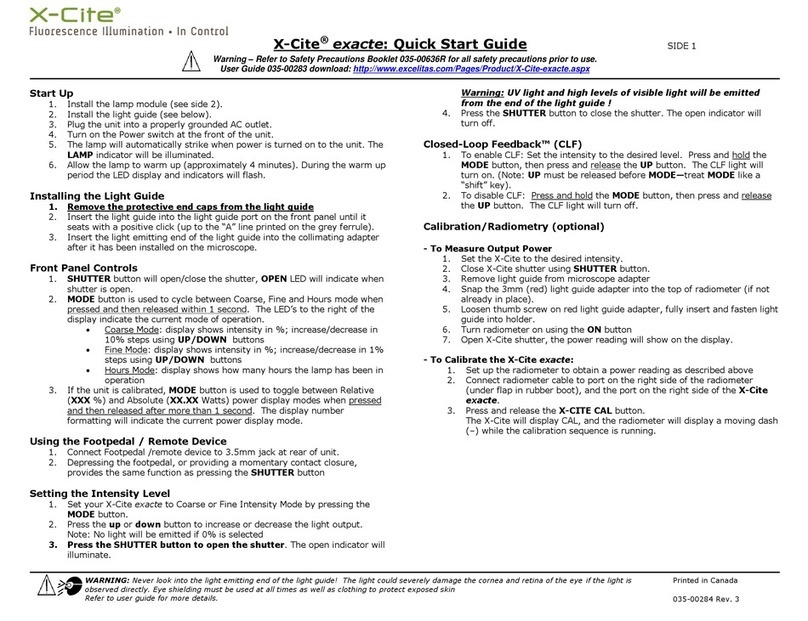
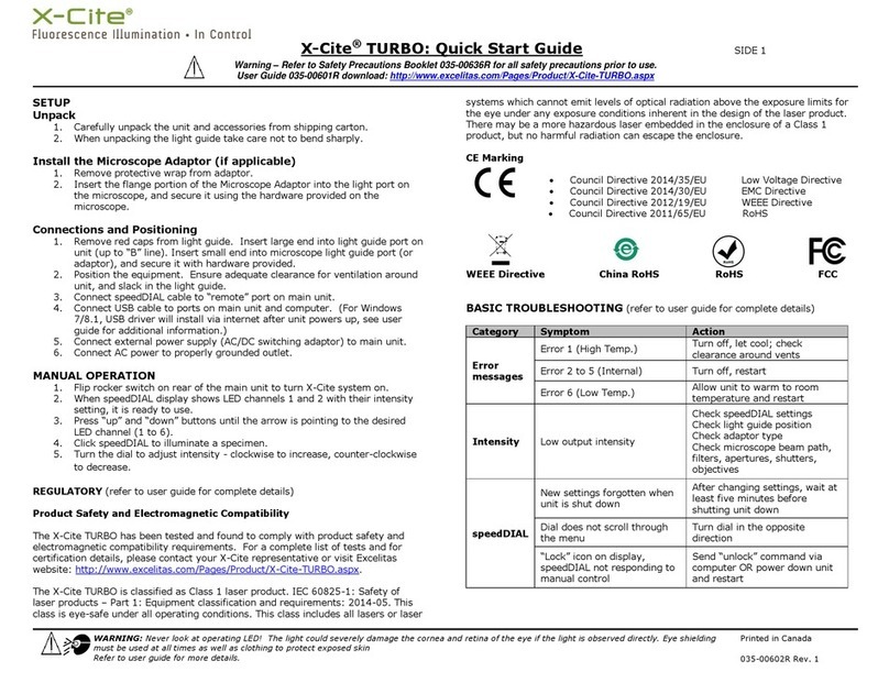
Excelitas Technologies X-Cite NOVEM Series User manual

X-Cite®NOVEM User Guide
Applies to X-Cite NOVEM Models:
XT910 / XT910-F
XT920 / XT920-F
XT930 / XT930-F
XT940 / XT940-F

2
X-Cite® NOVEM User Guide
035-00710R rev 0
X-Cite® NOVEM User Guide
035-00710R rev.0
Made in Canada
Excelitas Canada Inc. 2021
All rights reserved
No part of this publication may be reproduced, transmitted, transcribed, stored in a retrieval system or
translated into any language in any form by any means without the prior written consent of Excelitas
Canada Inc. Every effort has been made to ensure information in this manual is accurate; however,
information in this manual is subject to change without notice and does not represent a commitment on
the part of the authors.
Excelitas Canada Inc.
2260 Argentia Road
Mississauga ON L5N 6H7 CANADA
Trademarks
X-Cite®is a registered trademark of Excelitas Canada Inc. All rights reserved.
All other product names are trademarks of their respective owners.

3
X-Cite® NOVEM User Guide
035-00710R rev 0
Table of Contents
1Safety.........................................................................................................................................6
1.1 Glossary of Symbols ......................................................................................................................6
1.2 Safety Precautions ........................................................................................................................6
2Getting Started...........................................................................................................................8
2.1 System Components .....................................................................................................................8
2.2 System Layout.............................................................................................................................10
2.3 Installation/Set-up ......................................................................................................................13
3Operation –Manual Control .....................................................................................................17
3.1 The Basics....................................................................................................................................17
3.2 SpeedDIAL Menu and Settings....................................................................................................19
3.2.1 SpeedDIAL Menu Structure.................................................................................................19
3.2.2 LCD –Display Screen Brightness and Color Settings...........................................................20
3.2.3 Group –Grouping Mode Control........................................................................................20
3.2.4 Hand –Display Screen Orientation.....................................................................................20
3.2.5 Info......................................................................................................................................20
3.2.6 Srvc –Service Data..............................................................................................................21
3.2.7 Err........................................................................................................................................22
4Operation - External Control .....................................................................................................22
4.1 USB/RS-232.................................................................................................................................22
4.1.1 Driver Installation (automatically via internet)...................................................................22
4.1.2 Driver Update (via ZIP file)..................................................................................................23
4.1.3 Verify Installation & Get COM Port Number.......................................................................24
4.1.4 Software Developer’s Kit (SDK)...........................................................................................25
4.1.5 Commercial Software Support............................................................................................25
4.1.6 Grouping Controls / Compatibility Mode ...........................................................................26
4.2 TTL & Analog ...............................................................................................................................27
4.2.1 TTL Input Specifications ......................................................................................................27
4.2.2 TTL Signal and LED Status....................................................................................................27
4.2.3 Analog Input Specifications.................................................................................................27
4.2.4 Analog Signal and LED Power Setting .................................................................................27
4.2.5 DB15 Pin-Out and Cable Labels –TTL Input........................................................................28
4.2.6 DB15 Pin-Out and Cable Labels –Analog Input..................................................................28
4.3 Tips for Specific Use Cases..........................................................................................................29
4.3.1 Simultaneous Control to produce White Light Mode –USB ..............................................29
4.3.2 Simultaneous Control to produce White Light Mode –TTL & Analog................................29
4.3.3 Ring Buffer / TTL Sequencing Mode....................................................................................29
4.4 Response Times ..........................................................................................................................30
4.4.1 ON/OFF ...............................................................................................................................30
4.4.2 Rotary Filter Changer ..........................................................................................................30
4.5 Photodiode Sensor and Intensity Monitoring.............................................................................30
5Troubleshooting .......................................................................................................................31
5.1 Error Messages............................................................................................................................31
5.2 Failure to Power Up ....................................................................................................................32

4
X-Cite® NOVEM User Guide
035-00710R rev 0
5.3 Low Illumination Intensity ..........................................................................................................33
5.4 Other Potential Symptoms & Questions.....................................................................................34
6Routine Care and Maintenance.................................................................................................35
6.1 General........................................................................................................................................35
6.2 Cleaning - Exterior Surfaces ........................................................................................................35
6.3 Cleaning - Optical Surfaces .........................................................................................................35
7Technical Specifications ............................................................................................................37
7.1 General........................................................................................................................................37
7.2 Electrical......................................................................................................................................37
7.3 Environmental –Operating Conditions ......................................................................................37
7.4 Environmental –Transport and Storage Conditions...................................................................37
7.5 Input/Output (I/O) Connections .................................................................................................38
7.6 Output Stability...........................................................................................................................38
8Regulatory Compliance.............................................................................................................39
8.1 Product Safety and Electromagnetic Compatibility....................................................................39
8.1.1 Laser Safety.........................................................................................................................39
8.1.2 Optical Safety......................................................................................................................39
8.2 CE Marking..................................................................................................................................40
8.3 FCC ..............................................................................................................................................40
8.4 WEEE Directive............................................................................................................................41
8.5 China RoHS..................................................................................................................................42
8.6 Korean KC Certification...............................................................................................................43
8.7 Australia - RCM ...........................................................................................................................43
9Warranty & Repairs..................................................................................................................44
9.1 Warranty Terms..........................................................................................................................44
9.2 Returning equipment to Excelitas...............................................................................................45
10 Contact Information..............................................................................................................46
10.1 General........................................................................................................................................46
10.2 Technical Support and Service....................................................................................................46
10.3 Accessories and Replacement Parts ...........................................................................................46
Table of Figures
Figure 1 Front and Rear Panel Connections.................................................................................................9
Figure 2 SpeedDIAL ......................................................................................................................................9
Figure 3 LED and Filter Layout for All System Configuration Options ........................................................12
Figure 4 Single Filter and Rotary Filter Brackets .......................................................................................14
Figure 5 Correct position for fully inserted X-Cite LLG and LLG with A and B insertion lines...................16
Figure 6 speedDIAL Display –Turning LED ON/OFF...................................................................................18
Figure 7 SpeedDIAL Display –Lock Screen.................................................................................................18
Figure 8 Device Manager, COM Port Listing...............................................................................................25

5
X-Cite® NOVEM User Guide
035-00710R rev 0
Introduction
More Power. More Wavelengths. More X-Cite®.
The Excelitas X-Cite NOVEM™ has it all. With high power output, a wide spectral range and convenient
design features, this 9-channel LED illuminator does everything but compromise.
X-Cite NOVEM provides researchers with fluorophore imaging options never before available. With five
independent LEDs and our patented LaserLED Hybrid Drive® powering four additional channels, X-Cite
NOVEM is the most versatile X-Cite platform, offering full spectral coverage that extends further than
any previous X-Cite system -- from Fura-2 all the way to IR800.
Preinstalled clean-up filters and a four-position motorized filter changer offer an unprecedented level of
convenience. Avoid unnecessary hassle during initial set-up, and then let X-Cite NOVEM’s filter changer
automatically move the appropriate green-yellow filters into place as needed.
Whatever the application, from slide scanning to FISH, Fura-2 to IR800, X-Cite NOVEM has it covered!
Excelitas recommends reading this manual to discover all the features available in X-Cite NOVEM.
Thank you for choosing X-Cite!
This product is intended for use in fluorescence illumination. It allows researchers the ability to excite
fluorescence in samples being studied and characterize their location or behavior.
Excelitas Technologies Corp. is a global technology leader focused on delivering innovative, customized
solutions to meet the lighting, detection and other high-performance technology needs of customers. X-
Cite, formerly of Lumen Dynamics (which was acquired by Excelitas Technologies Corp. in November
2013) offers the Life Science and Analytical Instrumentation market a broad range of innovative lamp
and LED fluorescence illumination and measurement solutions. Recognized as the industry standard in
research microscopy, X-Cite also provides solid state LED technologies to instrument manufacturers, and
combines maximum optical performance with flexible design, as well as best-in-class manufacturing
quality and lead time.

6
X-Cite® NOVEM User Guide
035-00710R rev 0
1Safety
1.1 Glossary of Symbols
Symbol
Meaning
CAUTION - Risk of danger: consult accompanying
documents
WARNING –Eye damage may result from directly viewing
ultraviolet light. Protective eye shielding and clothing
must be used at all times.
WARNING –UV light hazard.
IEC 60825-1: Safety of laser products –
Part 1: Equipment classification and
requirements: 2014-05
WARNING –Class 1 laser product.
Input/Output Signals
Input Signal
CAUTION –Hot surface
1.2 Safety Precautions
Please observe the following safety precautions at all times during operation and maintenance of this
product. Failure to do so may result in personal injury or property damage.
1. UV emitted from this product. Avoid eye and skin exposure to unshielded product. Do not look
at operating lamp/LED. Eye injury may result.
2. Never look into the light emitting end of the light guide. The light could severely damage the
cornea and retina of the eye if the light is observed directly. Eye shielding must be used at all
times as well as clothing to protect exposed skin.
3. Always make sure the light guide and microscope adapter (if applicable) are securely attached to
the microscope prior to turning on power to the unit. This will minimize the risk of exposure to
the UV light.

7
X-Cite® NOVEM User Guide
035-00710R rev 0
4. Always use this product with the external power supply and power cord set provided. Ensure
the external power supply cord is connected to a grounded 3-pin outlet only. Any substitution of
these components will invalidate regulatory certification of this product and may impair
operating safety.
5. Disconnecting of main supply source is done by putting the on/off button in the off position and
unplugging the power cord.
6. It is recommended that ONLY QUALIFIED TECHNICAL PERSONNEL perform any testing or repairs
of this unit. If servicing the unit, disconnect the external power supply before opening the
cover of this unit. All cover screws must be replaced prior to applying power to the unit, or
safety of the unit will be impaired. Note that opening the cover and/or altering the unit in any
way may void the warranty (see section 10 for more details).
7. Monitoring the unit during manual operation
The level of UV and visible energy supplied by this product is sufficient to ignite flammable
substances. During manual operation, the unit must be attended at all times by a qualified
operator. The unit must not be left unattended while turned on. If an operator leaves the work
area of the unit, the power switch must be turned off.
8. Monitoring the unit during automated operation
The level of UV and visible energy supplied by this product is sufficient to ignite flammable
substances. Therefore, when the unit is operated unattended in an automated environment, an
alarm function must be provided by the user to indicate a malfunction in the associated
equipment used.
9. Should this X-Cite unit be used in a manner not specified by Excelitas, the protection provided
by the equipment may be impaired.
10. This unit is designed for bench top use only! Always ensure that the unit is placed on a hard,
stable surface, ensuring that ventilation openings are not obstructed. Any obstruction of these
openings could result in a possible over-heating condition.
11. To clean the exterior of the unit, use a slightly dampened cloth and a simple water/ detergent
solution only. Avoid the optical surfaces and lenses. Cleaning of optics should only be attempted
by qualified personnel using appropriate fluids and lens paper.
12. The unit has an embedded class 4 laser that should not be tampered with or accessed.

8
X-Cite® NOVEM User Guide
035-00710R rev 0
2Getting Started
2.1 System Components
This X-Cite system contains the following components:
1. X-Cite NOVEM unit (Series XT900), LEDs and dichroics are installed.
2. Clean-up Filters, installed (model numbers ending in “-F” only)
3. SpeedDIAL Manual Controller
4. Power Cord
5. Microscope Adaptor (if ordered)
6. Accessories Box, containing:
a. Quick Start Instruction Sheet (User Guide and Software download are available on
Excelitas website: https://www.excelitas.com/)
b. Hex Tools (Allen Keys), 3mm, 1.5mm and 0.05”
c. USB Cable
d. Light Guide (if ordered)
e. TTL/Analog Trigger Cable, DB15 to 9 x BNC
f. Safety Precautions Booklet
If any components are missing or appear damaged, please contact Excelitas immediately.
Note: one TTL/Analog Trigger Cable is supplied per unit. To control the X-Cite NOVEM via both TTL and
analog, a second cable must be ordered.

9
X-Cite® NOVEM User Guide
035-00710R rev 0
Figure 1 Front and Rear Panel Connections
Figure 2 SpeedDIAL
“up” / “down”
buttons
Rotating Dial
Display Screen (LCD)

10
X-Cite® NOVEM User Guide
035-00710R rev 0
2.2 System Layout
The LEDs installed in the unit, and their positions, depend on the configuration type. The X-Cite unit
contains the following LED wavelengths:
Fluorophore
Wavelength
LED Position
Notes
XT910
XT920
XT930
XT940
FURA-2
340
9
DAPI
365
1
1
DAPI
385
1
1
CFP
435
2
2
2
2
FITC
475
3
3
3
3
YFP, TRITC,
mCherry
HD
(LaserLED
Hybrid Drive
500-600)
4
4
4
Powered by LaserLED
Hybrid Drive. 500-
600nm broad peak,
selectable with
motorized rotary filter
changer
5
5
5
4
6
6
6
5
7
7
7
6
Cy5
635
8
8
8
7
Cy7
735
9
9
8
IR800
785
9
The LEDs and filters (if installed) are positioned as shown in Figure 3.
Clean up Filters Installed in Configuration Option XT910-F
Channel
Fluorophore
Wavelength
Filter Installed
1
DAPI
365
378/52
2
CFP
430
438/24
3
FITC
475
474/27
4
Blank Filter
HD (500-600)
5
YFP
510
509/22
6
TRITC
555
554/23
7
mCherry
580
578/21
8
Cy5
635
635/18
9
Cy7
735
735/28

11
X-Cite® NOVEM User Guide
035-00710R rev 0
Clean up Filters Installed in Configuration Option XT920-F
Channel
Fluorophore
Wavelength
Filter Installed
1
DAPI
385
378/52
2
CFP
430
438/24
3
FITC
475
474/27
4
Blank Filter
HD (500-600)
5
YFP
510
509/22
6
TRITC
555
554/23
7
mCherry
580
578/21
8
Cy5
635
635/18
9
Cy7
735
735/28
Clean up Filters Installed in Configuration Option XT930-F
Channel
Fluorophore
Wavelength
Filter Installed
9
FURA-2
340
1
FURA-2/DAPI
385
387/11
2
CFP
430
438/24
3
FITC
475
474/27
4
Blank Filter
HD (500-600)
5
YFP
510
509/22
6
TRITC
555
554/23
7
mCherry
580
578/21
8
Cy5
635
635/18
Clean up Filters Installed in Configuration Option XT940-F
Channel
Fluorophore
Wavelength
Filter Installed
1
DAPI
365
378/52
2
CFP
430
438/24
3
FITC
475
474/27
4
YFP
510
509/22
5
TRITC
555
554/23
6
mCherry
580
578/21
7
Cy5
635
635/18
8
Cy7
735
735/28
9
IR800
785
775/46

12
X-Cite® NOVEM User Guide
035-00710R rev 0
Figure 3 LED and Filter Layout for All System Configuration Options

13
X-Cite® NOVEM User Guide
035-00710R rev 0
2.3 Installation/Set-up
For additional assistance with installation and set-up, videos are available. Refer to the X-Cite NOVEM
website under “related content”.
1. Unpack
a. Carefully unpack the unit and accessories from the shipping carton.
b. When unpacking the light guide (liquid or quartz fiber), take care not to bend sharply or
kink.
2. To remove or change clean-up filters in Single Filter Brackets:
Important: Ensure that main unit is powered OFF before attempting to install filters
a. Lay the X-Cite unit on its side, access panel side up. Remove the filter access panel with
the 3mm hex tool.
b. Refer to Figure 3 to determine location of specific LEDs.
c. Slide out the relevant filter brackets by grasping the black “tabs”.
d. Remove filter:
i. Loosen set screw at bottom of filter bracket.
ii. Over a clean surface, turn filter bracket over, letting the filter drop out.
e. Install filter:
i. Place 25mm mounted filter in the bracket in the correct orientation advised by
the filter manufacturer. Secure set screw.
ii. Over a clean surface, turn filter bracket over to ensure the filter is firmly
installed.
iii. Repeat for any additional filters being installed.
f. Reinstall the filter bracket(s) by aligning the holes with the locator pins, and gently
sliding the bracket all the way in.
g. Reattach the filter access panel.

14
X-Cite® NOVEM User Guide
035-00710R rev 0
Figure 4 Single Filter and Rotary Filter Brackets
3. To install, remove or change clean-up filters in Rotary Filter Changer
Important: Ensure that main unit is powered OFF before attempting to install filters
a. Lay the X-Cite unit on its side, access panel side up. Remove the filter access panel with
the 3mm hex tool.
b. Refer to tables in section 2.2 determine location of filters for specific LEDs in the rotary
filter changer (positions 4-7).
c. Gently rotate the assembly until the desired position number is showing.
d. Block the gaps with the X-Cite filter shield, KimWipe, or paper to avoid losing parts.
e. Remove relevant filter bracket by loosening the set screw on the right (A), and
detaching bracket from the rotary assembly.
f. Remove filter:
i. Loosen set screws (B) at bottom of filter bracket.
ii. Over a clean surface, turn filter bracket over, letting the filter drop out.
g. Install filter:

15
X-Cite® NOVEM User Guide
035-00710R rev 0
i. Place 25mm mounted filter in the bracket in the correct orientation advised by
the filter manufacturer. Secure set screws (B).
ii. Over a clean surface, turn filter bracket over to ensure the filter is firmly
installed.
iii. Reinstall the filter holder on the rotary assembly and secure the set screw (A).
h. Remove X-Cite filter shield or other gap blocking material so that rotary filter assembly
can turn freely.
i. Repeat for any additional filters being installed.
j. Reattach the filter access panel.
4. Install the Microscope Adaptor (if applicable)
a. Remove the protective wrap from the Microscope Adaptor, being careful not to touch
the lens surfaces.
a. Insert the flange portion of the Microscope Adaptor into the light port on the
microscope, and secure it using the hardware provided on the microscope. (Refer to
relevant microscope user manual for complete instructions on mounting a standard epi-
fluorescence lamphouse.) General guidelines:
i. Carl Zeiss –Tighten the hex fastener on the side of the light port with the 3mm
Hex Tool.
ii. Leica - Tighten the hex fastener on the side of the light port with the 3mm Hex
Tool.
iii. Nikon –Line up the “notch” with the pin on the microscope fitting, hold the
adaptor firmly against the light port, and twist the collar to lock the components
together.
iv. Olympus - Tighten the hex fastener(s) with the 3mm Hex Tool. Depending on
the model, there may be one (1) fastener on the side, or two (2) fasteners
located at the 10:00 and 2:00 positions.
5. Install the Light Guide
a. Remove the red plug from the light guide port located on front fascia.
b. Remove the red caps from the ends of the light guide.
c. Insert the larger end of the light guide into the light guide port. For this X-Cite unit, the
light guide must be inserted up to the “B” line printed on the grey ferrule, see Figure 5.
[Note: If using an X-Cite 3mm or 5mm light guide with only one “insertion line” on the
grey ferrule, this line will be 20mm away from the light guide port.]
d. Insert smaller end of the light guide into the Microscope Adaptor (or light guide port on
the microscope/imaging instrument). Ensure that light guide is fully inserted and lock in
place with thumbscrew (or appropriate fastener).

16
X-Cite® NOVEM User Guide
035-00710R rev 0
Figure 5 Correct position for fully inserted X-Cite LLG and LLG with A and B insertion lines
6. Check Position of the Equipment
a. The X-Cite unit should be positioned to avoid sharp bends and strain on the light guide.
This applies to both liquid and quartz fiber light guides. Ideally, the unit should be
positioned so that:
i. The light guide has as few bends as possible.
ii. Bends have the largest bend radius possible.
iii. There is some slack in the light guide.
b. To avoid overheating the LEDs and other electronics, ensure all air vents on the side
panel and rear of the unit are clear of obstruction and have ready access to room
temperature air. Recommended clearance is 20cm (8 inches).
c. If installing the unit within another imaging instrument, the air vent side should be
placed against an outside panel with venting to allow fresh air to be drawn into the
system. The system exhausts via the bottom.
7. Connect speedDIAL to main unit
a. Important: Ensure that main unit is powered OFF before attempting to connect
speedDIAL, or damage to the device may result.
b. Insert the mini DIN plug into the “speedDIAL” port on the rear of the unit. Ensure the
arrow mark on the connector is on the right (i.e. at the 3:00 position). Note: Never
force the connector –this can damage the pins. If connector does not insert smoothly,
stop and check for bent pins.
c. Place speedDIAL next to the microscope, or another easily accessible location.

17
X-Cite® NOVEM User Guide
035-00710R rev 0
8. Connect USB (if using)
a. Insert “B” (square) end into the “USB” port on rear of the unit.
b. Insert “A” (flat) end into an available port on the computer.
c. Note: For best performance, use the supplied USB cable (or one of equivalent quality
and length), and plug directly into the computer. Using a USB hub or longer USB cable
than the one supplied may result in intermittent communication errors.
9. Connect TTL/Analog Trigger Cable (if using)
a. Insert DB15 end into the port on rear of the unit. Tighten fasteners with a flat head
screwdriver (e.g. 1/8 inch, not included)
b. Connect BNC cables to appropriate signal generating device. BNC connectors are
labeled with channel numbers.
10. Connect AC Power
a. Connect Power Cord: Connect female end of the power cord to AC port on the power
supply. Connect male end to a properly grounded electrical outlet.
b. For safe operation, use only the power cord supplied or one with an equivalent rating.
3Operation –Manual Control
3.1 The Basics
1. Start the unit
a. Flip the rocker switch on front of the main unit to turn X-Cite system on.
b. The system will have a brief initialization period (approximately 5 seconds). The
speedDIAL display will show “X-Cite” during this time.
c. When the display shows LED positions 1 and 2 with their intensity setting (a number
from 5 to 100), it is ready to use.
d. Note: If speedDIAL will be used for manual control, it must be connected before
turning system on. SpeedDIAL can be damaged if it is plugged into, or unplugged
from, the system while it is powered on.
2. Illuminate a specimen
a. Press the “up” and “down” buttons the desired LED channel (1 to 9) is displayed.
b. Click the dial (shutter button) on speedDIAL to turn on/off the excitation light. A
check mark will appear beside the LED channel numbers that are ON. (See Figure 6 –
Channel 8 is on at 100% intensity.)
c. To turn all LEDs ON/OFF at once, move arrow to “All” at the bottom of the list. Click
the dial.

18
X-Cite® NOVEM User Guide
035-00710R rev 0
-Note: Using the “All” function on X-Cite NOVEM-FURA (models XT930 and
XT930-F) is not recommended. The 340nm LED has a lower maximum
temperature limit than the other LEDs. The heat generated while all LEDs are
on may trigger an overheating error (Error 1) on the 340nm LED.
Figure 6 speedDIAL Display –Turning LED ON/OFF
3. Adjust intensity
a. Press the “up” and “down” buttons to the LED to be adjusted.
b. Turn the dial to adjust intensity - clockwise to increase, counter-clockwise to decrease.
intensity is updated in real time)
c. Repeat for any other LEDs requiring adjustment.
d. The dial is speed sensitive –turning slowly will allow adjustments in smaller
increments, turning quickly will increase the step sizes.
e. Intensity can be adjusted in 1% increments from 5% to 100%.
f. NOTE: If the LEDs are Locked via PC, the “Lock” symbol will briefly display if the
rotating dial is pressed/turned (Figure 7). SpeedDIAL control can only be unlocked
via PC control, or by power cycling the unit.
Figure 7 SpeedDIAL Display –Lock Screen

19
X-Cite® NOVEM User Guide
035-00710R rev 0
3.2 SpeedDIAL Menu and Settings
In addition to the intuitive intensity adjustment and illumination ON/OFF control, speedDIAL has several
advanced settings and control options.
To access the main menu, press and hold the dial for one (1) second.
To navigate the menus, turn the dial to scroll through the options. An arrowhead will indicate
the currently selected menu option; click the dial to make a selection.
To adjust settings, turn the dial. To exit the setting adjustment, click the dial.
To exit the menu system at any time, press and hold the dial for one (1) second, or select Exit at
the bottom of the menu list.
Note: Setting changes will take effect immediately during selection. However, for the first five (5)
minutes, the new settings are not saved for restoration after power cycle. If the X-Cite unit is powered
down during this time, settings will revert back to their previous values. To ensure that new settings will
be remembered, wait at least five (5) minutes after the last settings adjustment before powering down
the unit. “Up” and “down” buttons are disabled in the speedDIAL menu and settings.
3.2.1 SpeedDIAL Menu Structure
LCD
Dim
Brig
Color
Exit
Group
Hand
Info
LED1
oHour, Wave, FWH, WLR,
Temp, Max
LED2 to LED9
(same as LED1)
Exit
Srvc
SN
S/W1
S/W2
Spd (no function in X-Cite XXX)
Exit
Err
Exit

20
X-Cite® NOVEM User Guide
035-00710R rev 0
3.2.2 LCD –Display Screen Brightness and Color Settings
In the LCD sub menu, the time before the backlight is turned off (the backlight will turn back on
with a movement of the speedDIAL), the backlight on the display screen can be turned on/off,
set to a different brightness level, or set to a different color.
a. Select the “LCD” option from main menu.
b. To adjust LCD display backlight time out:
i. Select “Dim” and scroll through the time out options, which are: Off and 1 thru
999 seconds in 1 second increments. “Off” will turn off the backlight timer (i.e.
backlight will always be on).
ii. Click dial to return to “LCD” menu.
c. To adjust LCD brightness:
i. Select “Brig” and scroll through % brightness settings until the desired level is
reached. To turn backlight off, set level to 0%.
ii. Click dial to return to “LCD” menu.
d. To change LCD color:
i. Select “Color” and scroll up /down through the options until desired color is on
LCD.
ii. Click dial to return to “LCD” menu.
e. Select “Exit” to go back to the main menu, or press and hold dial to return to the home
screen.
3.2.3 Group –Grouping Mode Control
In this menu, “Grouping Mode” can be turned ON or OFF. For more information on creating
groups, see section 4.1.6.
a. Select “Group” option from main menu.
b. Turn dial to toggle between “ON” and “OFF”.
c. Click dial to return to the main menu.
3.2.4 Hand –Display Screen Orientation
In this menu, the LCD orientation can be rotated 180°. This allows operators to use speedDIAL
on the left or right side of the microscope without blocking the view of the display with their
hand.
a. Select “Hand” option from main menu.
b. Turn dial to toggle between “Right Hand”and “Left Hand” operation. Note that the
screen will flip while adjusting this setting.
c. Click dial to return to the main menu.
3.2.5 Info
In this menu, information specific to each LED may be found. This includes total hours
accumulated on the LED, center wavelength, full width half maximum of each LED, useable
wavelength range and temperature.
This manual suits for next models
8
Table of contents
Other Excelitas Technologies Laboratory Equipment manuals

Excelitas Technologies
Excelitas Technologies X-Cite XLED1 User manual

Excelitas Technologies
Excelitas Technologies X-Cite Exacte User manual

Excelitas Technologies
Excelitas Technologies OmniCure AC2 Series Installation and operating manual

Excelitas Technologies
Excelitas Technologies X-Cite TURBO User manual

Excelitas Technologies
Excelitas Technologies X-Cite 120LEDBoost User manual

Excelitas Technologies
Excelitas Technologies X-Cite XYLIS XT700 Series User manual

Excelitas Technologies
Excelitas Technologies OmniCure S1500 PRO User manual