± 0.05 ~
6A, 0.6kVA
3.5kg
138W x 150D x 312H (Excluding any projection)
5 ~ 35°C
AC-100V 50/60Hz
11A, 1.1kVA
500W (SUS316L) 1kW (SUS316L)
7L / min
(50 / 60 Hz / water / high circulation)
1.2m / 1.5m
(50 / 60 Hz / water / high circulation)
± 0.1 ~
2
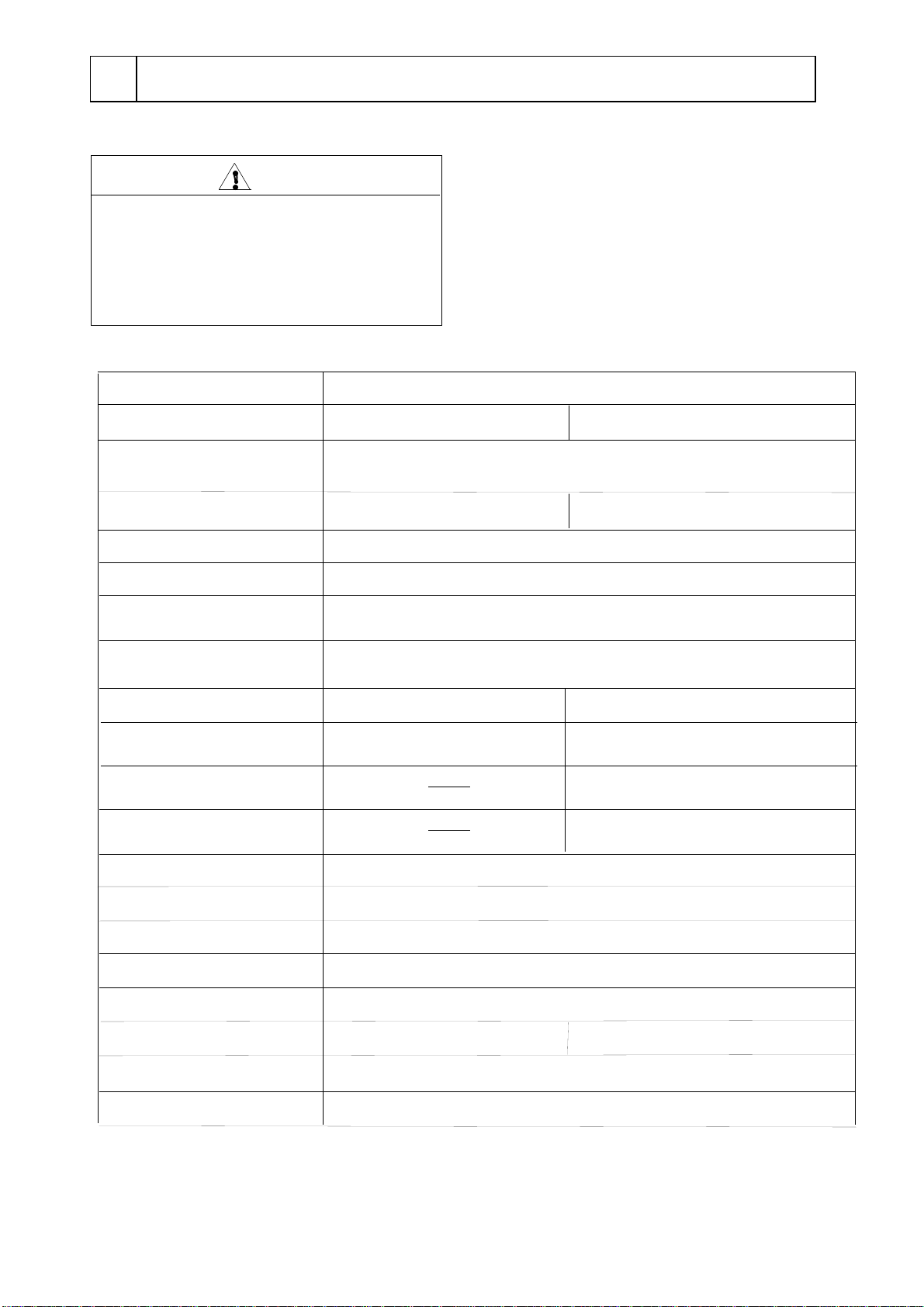
Outline
Warning
Do not remodel.
Do not use out of applications.
Remodeling or use out of applications may
cause an electric shock or mechanical troubles.
This unit is applicable for wide variety of
experiments / examinations of reaction,
crystallization, synthesis, deposition of organic
steel, environmental tests of materials,
breakdown tests, endurance test, and such.
Room Temperature (RT) +5℃〜80℃(If you use a supplied bath, Max.
70°C) * 1 (If you use this with a cooling bath, -20〜RT+5℃)
Alarm function (Low water level, Over shoot, Control, Sensor),
Variable independent over temperature protector, Circuit protector
Changeable jet flow
Thermistor
Auto-tuning, Temperature calibration, Auto-stop 1, Auto-stop 2,
Auto-start, Selectable operation after power failure
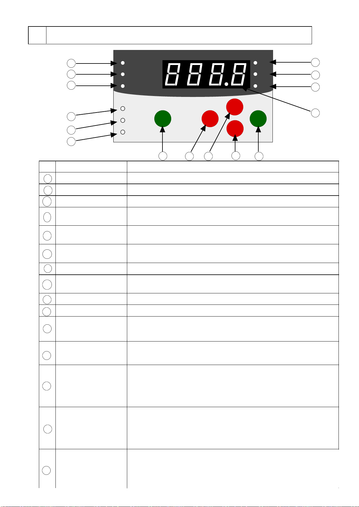
Digital setting by membrane switch, digital read-out by 0.1°C
PID microprocessor control, SSR output
Model
Name of product
Heater output
Safety features
Temperature control
Temp. settings / indication
Additional functions
Temp. control accuracy
Temp. control range
Temperature sensor
Stirring method
Max. flow rate of
Max. head of circulation pump
circulation pump
Applicable ambient temp. range
Overall dimensions
Net weight
Power source input
Rated power source
(Possible external circulation)
Protection cover
Water bath
Anti-bacterial stainless steel-made
Self-extinguishing resin (Max. 70°C) 9L capacity
* 1 Use an anti-freeze solution when the temperature is 10°C or lower.
If you use at Room temperature + 5°C or lower, combine with other cooling unit such as an immersion
cooler or a cooling water circulator, etc.
* 2 The performance is shown at room temperature 20°C , 100V, 50Hz, using a supplied water bath filled
with 7L water without lid.
*2
Immersion type Thermo regulating bath
Propeller by stirring speed control