3
==Notice ==
When you require to perform continuous operation of 24 hours/day under temp. of less than
0deg℃for more than one week duration.
Please contact us.
We will propose customized version of the chiller for such cases.
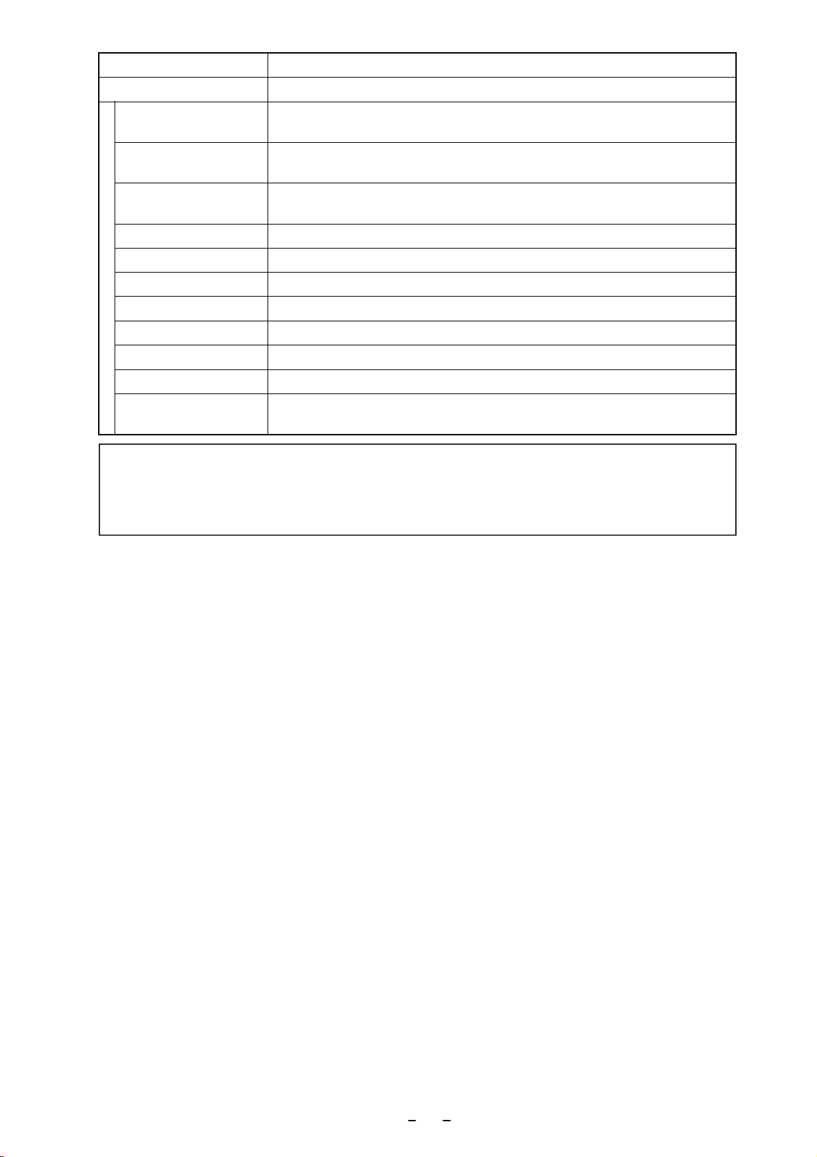
Product name Low temperature circulator (Cool Ace)
Model CA-1116A
S
P
E
C
.
Range of ambient
temperature 5~40℃( Indoor use only) ※5
Range of ambient
humidity 20~80% ( Indoor use only )
Dimensions ※6
(main unit)354(W)×384(D)×851(H)(excluding nozzle)
Dimension of the bath 280 (Diameter)×270 (Depth)
Supply voltage AC 220V±10% 50/60Hz
Supply power ※7 4.3A 950 VA
Weight Approx. 43 kg
Operation presser max. 2.45 MPa
Pollution degree 2
Over voltage category Ⅱ
Operation at a
terrestrial altitude Max 2000m above sea level
※1 ・Heater is not equipped.
・Temperature control not available when the ambient temperature is low, unloaded and high
temperature setting.
※2 Condition
・Room temperature 20℃・Water 14ℓ・Circulation flow Max. ・Setting 5~30℃
・Heat load Less than 90% of cooling capability(displayed capability)
・Power source AC 220V 50Hz
・In some cases the accuracy differs depending on room temperature, supply power, type of
refrigerant, the condition of stirring in the bath and etc.
※3 Condition
・Room temperature 20℃・Circulation volume Max. ・Supply power: AC 220V 50Hz
・Cooling capability is ±10%of displayed capability.
・Cooling capability differs depending on room temperature, supply power, voltage,
type of refrigerant, condition of stirring in the bath and etc.
※4 Condition
・Water temperature 20℃・Supply power / voltage AC 220V 50Hz
・Circulation capability is ±10%of displayed capability.
・Circulation capability differs depending on the type of secondary refrigerant.
※5 In order to guarantee the performance of the instrument described in this manual
ambient temperature must be within the range from 5 to 35℃.
※6 External dimension does not include protrusion.
※7 When voltage is dipped during operation, the unit may indicate “ A14 ” may be on the
control panel and then quit operation. However, this is not a fault of the unit.