EYELA FDS-1000 User manual

取扱説明書
Freeze dryer
Model FDS-1000
R00
Instruction Manual
This instruction manual is designed to use the product safely with keeping its best
performance.
Please keep this manual in a place easily accessible to every users.
IMPORTANT Be sure to read “Safety precautions” before use.
Tokyo Rikakikai Co., Ltd.
(230V)


IMPORTANT SAFETY INFORMATION
1. Warning signal word
Attempting to carelessly operate the product or to
touch the portion not-specified may result in
unexpected injury.
Most of such accidents can be prevented if such
danger is known beforehand.
To ensure the safety, this manual defines the
information on such matters as requiring particular
care in the safety as follows in terms of the
importance and risk and attaches the alert mark and
signal word.
It is recommended to follow the instruction to ensure
the safe use of the product.
We have undertaken thorough verification concerning the possible occurrence of risk in the
course of use of the product, but prediction of all and every kind of risk is extremely difficult.
Namely, cautions contained in this manual are not necessarily all of possible risks.
However, if the product is operated according to the procedure described in this manual, the
safe operation and work is ensured. Be sure to pay utmost care during handling of the product
to prevent accident or failure of the product.
Alert mark
Signal word Definition
Wrong handling is assumed to cause the possibility of the death
or heavy injury of the user.
Wrong handling is assumed to cause the risk of injury of the
operator or physical damages.
Warning
Caution

Leak filter
No. Nomenclature Quantity
1 Main body 1
2 Trap barrier 1
3 Leak filter 1
4 Tube 1
5Tube(spare)1
6 Connector 1
7Operation manual 1
8Guarantee 1
Tube
Tube (spare)
Trap barrier
1 For safe operations
2. Product Outline
2 - 1 Application
2 - 2 Specification
2 - 3 Sublimation rate data(reference)
2 - 4 Optional parts
2 - 5 Name of parts
3. Name and Functions of Parts
3 - 1 Control panel
3 - 2 Safety Functions
4. Installation
4 - 1 Installation environment
4 - 2 Installation conditions
4 - 3 Connecting the utilities
1
2
2
3
4
7
8
11
13
13
14
5. Operation
5 - 1 Preparation
5 - 2 Operation method
6. Troubleshooting Guide
7. Maintenance and Inspection
7 - 1 Replacing the consumables
7 - 2 Operation test of the leak breaker
7 - 3 Oil control of vacuum pump
Replacing the cartridge
7 - 4 Cleaning and care of the product
8. Disposal of Product
9. After-sale Services
10. Optional Products
15
20
29
32
33
33
34
35
36
37
Thank you for purchasing our product.
Introduction
This instruction manual explains
installation, operation, troubleshooting,
maintenance and inspection, and discarding
procedures for the Freeze dryer FDS-1000.
Always read this manual before use to
ensure familiarization of the product.
Contents
Be sure to confirm the kinds and quantities of parts before starting installation.
Package Contents
Connector

Be very careful when drying flammable substances, such organic
solvent, etc.
Solvent that cannot be trapped may be drawn by the vacuum pump,
possibly causing ignition and explosion
Take utmost care when drying the sample containing
flammable substances, such as organic solvent, etc.
Warning
- 1 -
●Carry out prior freezing of sample container.
●Change oil of the vacuum pump periodically.
1For safe operations
This product is not explosion-proof. Be sure to take extreme care for safety during
operation.
Caution Do not touch the cooling fin with bare hand during maintenance work. The
cooling fan is keen and may cut your hand.
Do not touch the cooling fin with bare hands.
Cooling fin

- 2 -
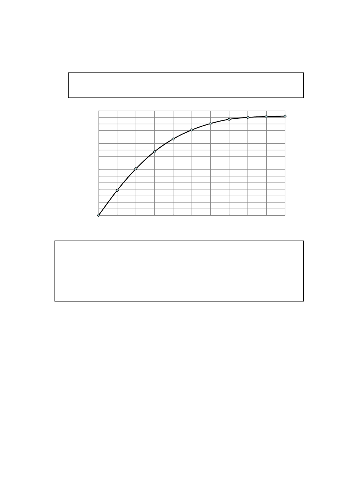
※1.The performance shown is at the ambient temperature of 20℃and at no load.
※2.The power input shown is the value not including the capacity of service outlet.
This product is applicable to drying of the
diluted aqueous solution of protein, enzyme, etc.
or drying of the extracted solution of biologic
sample or biotic sample (urine, blood serum, etc.).
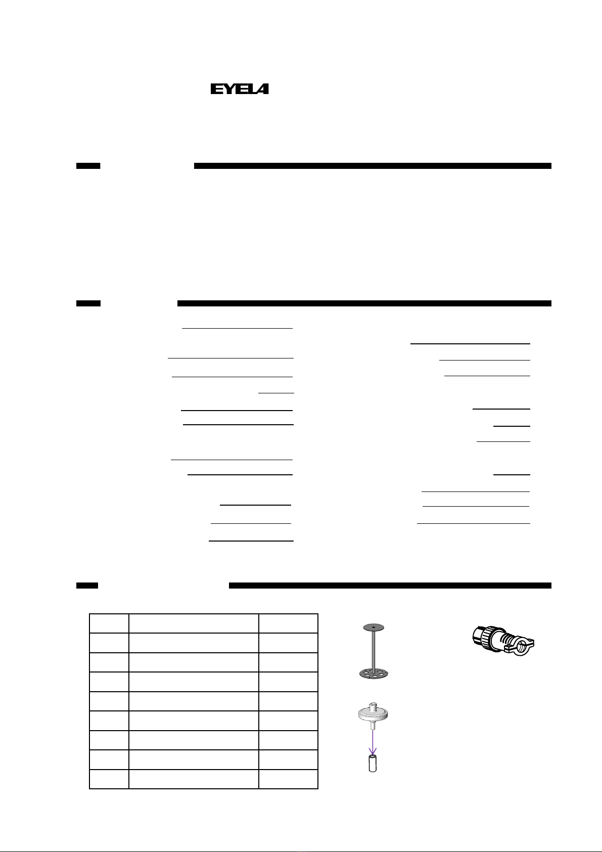
Product name Freeze dryer
Model FDS-1000
Cooling method Can body cooling
Perfor-
mance
Trap cooling temperature ※1 -80℃
Dehumidification rate 150mL/one batch
Function
Setting and display function Sheet key input and digital display
Safety function Leak/overcurrent breaker, circuit protector for socket outlet, refrigerator self-diagnosis
function, control board self-diagnosis function
Vacuum releasing function Automatic vacuum leak valve
Trap deicing function Deicing by the can body heater
Other functions Automatic vacuum pump operation, display of automatic vacuum pump operation
time, stopwatch function, freeze-drying ready display, selection of power recovery,
monitoring of vacuum abnormality, monitoring of trap temperature
Compo-
sition
Temperature sensor Ttype thermocouple sensor
Refrigerator, refrigerant Stirling refrigerator, helium(non-CFC)
Defrosting heater Silicon rubber heater, 60W
Standard
Vacuum pump (required
displacement) Option: 50L/min or more
Vacuum gauge
Pirani vacuum indicator:Digital display(0.0~533Pa)
Display accuracy at 0.4~4.0Pa ±2.0 Pa
at 4.1~10.0Pa ±3.0 Pa
at 10.1~15.0Pa ±4.0 Pa
at 15.1~40.0Pa ±7.0 Pa
Trap size (mm)・material Φ90×145(about 0.85L)・SUS304
Vacuum pump connection port
(mm) Outside diameter 17 (Rear side of main body)
Service socket Max.5A for both vacuum pump and driver chamber
Operating ambient temperature range 5~35℃
Outside dimensions (mm)(excluding
projection))455W×220D×497H
Weight About 19kg
Power input/rated power ※20.9A 200VA・AC230V 50Hz
2Product Outline
2-1 Application
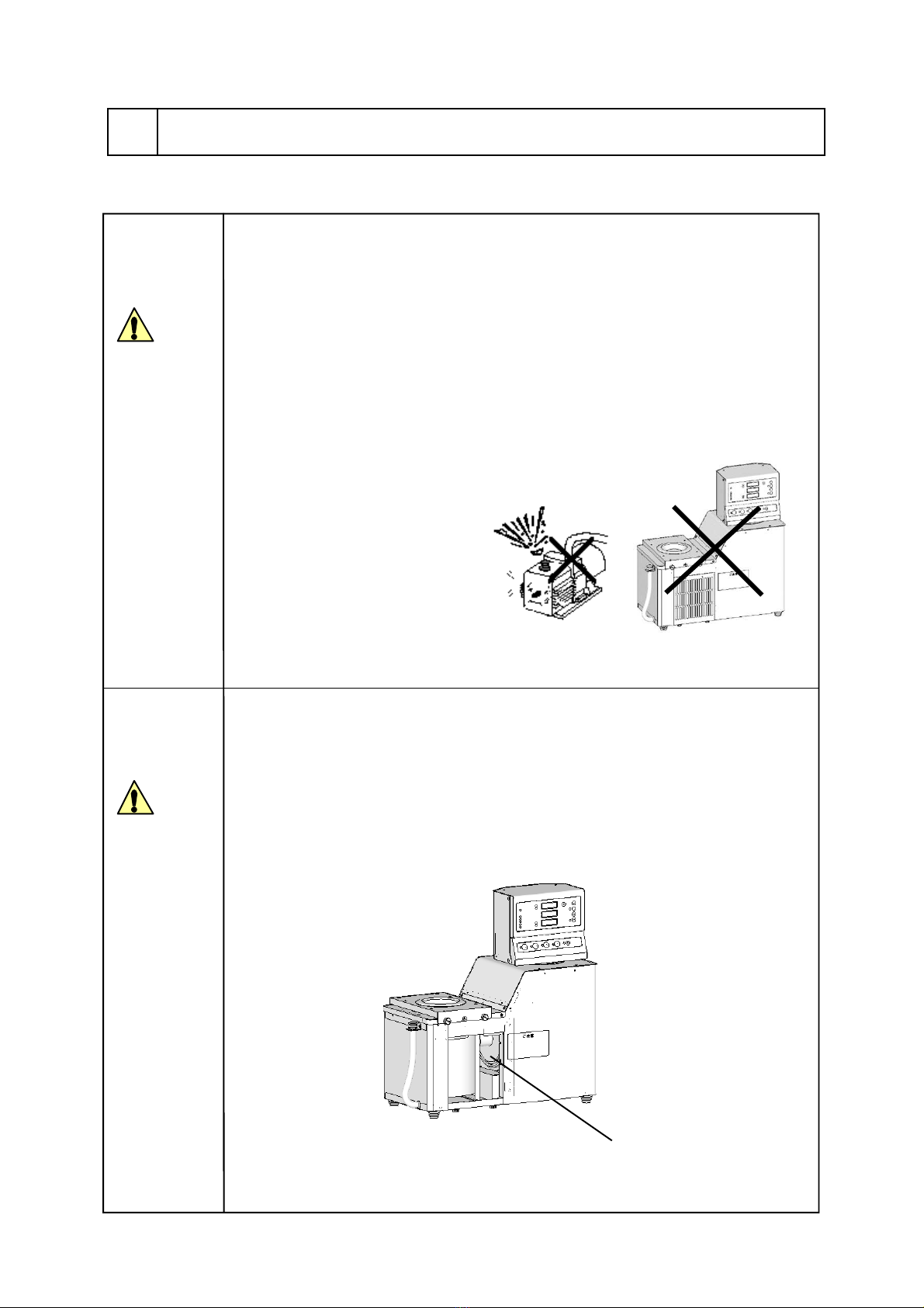
Never attempt to modify the product.
Operate the unit for the specified
purpose only.
An electric shock or a malfunction may result if the
product is modified or used for any purposes other
than that specified.
Warning
2-2 Specification

2-3 Sublimation rate data(reference)
・After prior freezing of four 100 mL sample (egg-plant shaped) flasks, each filled with 38g of water (a total
of 152g), they were installed to the trap. The sublimation rate was calculated back from the residue of flasks
after the time had passed.
Conditions ・AC230V,50Hz
・Ambient temperature 20℃
Sublimation
rate(g)
■Model FDS-1000
・The sublimation rate differs depending on the use conditions, such as the room temperature, capacity
and shape of sample containers (egg-plant shaped flask, freeze-drying bottle), type and amount of
samples, the degree of prior-freezing of samples.
・When the ambient temperature is 35℃, install one 100mL sample (egg-plant shaped) flask filled
with 40 g (max) of water (after prior freezing).
As the time passes, the trap time and the degree of vacuum decrease. When they decrease below the
set value, install the similarly-prepared container to he remaining adaptor.
0
10
20
30
40
50
60
70
80
90
100
110
120
130
140
150
160
0 1 2 3 4 5 6 7 8 9 10
Evaporation (g)
Time(h)
- 3 -

2-4 Optional parts
■Cock C,test tube, ampoule, etc.
①22
④
⑤
⑥③
② ⑦
⑧
⑨
⑩ ⑮
⑪⑫
⑬
⑭
⑯
⑰
⑱
⑲
⑳
22
※① The cock C belongs to the manifold. Prepare other adapters separately according to the intended use.
- 4 -

No. Name Standard Quantity Code No.
1 Cock C FD-1000,PMS-4S/4A(manifold for FDS-1000)1 191140
2 Adapter for ampoule For φ8 1 120520
For 6 1 120530
3 Ampoule Egg-plant shaped(1ml)20 120210
Pencil shaped with round bottom(1ml)20 120220
Pencil shaped with flat bottom(1ml)20 120221
Flat bottom(2ml)20 120230
Flat bottom(5ml)20 120240
Flat bottom(10ml)20 120250
Round bottom (2ml)20 120260
Round bottom (5ml)20 120270
Round bottom (10ml)20 120280
4 Type B adapter for test tube 1 120510
5 Sealing 1 145610
6 Rimmed test tube φ10×75(3ml)100 143970
φ12×75(4ml)100 143980
φ12×90(5ml)100 143990
φ12×105(6ml)100 144000
φ12×120(7ml)100 144010
φ13×75(5ml)100 144020
φ13×90(6ml)100 144030
φ13×100(7ml)100 144040
φ15×85(8ml)100 144050
φ15×105(10ml)100 144060
φ15×150(15ml)50 144070
φ16.5×10⁵(12ml)100 144080
φ16.5×165(20ml)50 144090
φ18×165(24ml)50 144100
φ18×180(27ml)50 144110
φ21×200(42ml)50 144120
7 Type C adapter for flask Taper size 29 1 191120
8 Sample flask For 50ml, taper size 29 1 116040
For 100ml, taper size 29 1 116150
9 Type C adapter for freezing bottle 1 191130
10 Cap (for freeze-drying Φ45, (for 40ml and 80ml)1 120020
11 Filter holder 1 120100
12 Filter 100 pieces/box 1 120110
13 Freeze-drying bottle 40ml (φ45)1 120050
80ml (φ45)1 120060
14 Freeze-drying bottle set 40ml 1 119940
80ml 1 119950
- 5 -

No. Name Standard Quantity Code No.
15 Cap (for freeze-drying bottle)φ70、(for 120ml, 150ml, 300ml)1 120030
16 Micro-tube holder 1.5ml×12 micro-tubes installed 1 191110
17 Freeze-drying bottle 150ml、φ70 1 120130
18 Freeze-drying bottle set Bottle:150ml、φ70 / cap:φ70 1 119970
19 Micro-tube holder 1.5ml×24 micro-tubes installed 1 191150
20 Freeze-drying bottle 300ml、φ70 1 120140
21 Freeze-drying bottle set Bottle:300ml、φ70 / cap:φ70 1 119980
22 Air filter 1 187450
■Drip box for egg-plant shaped flask Code No. 263490
The drip box receives drips of thawed frost adhering to the container outside when 50ml and 100ml flaks are used.
This is made from stainless steel and can be cleaned with ease.
- 6 -

2-5 Name of parts
Leak filter
Ventilation cover
Trap packing
Option fixing plate
Set screw (x 8)
Control panel
Receptacle x 2
(Commonly for vacuum pump and dry chamber)
Vacuum pump
connection port)
(OD φ17mm)
Circuit protector for
receptacle (5A)
Leak/overcurrent breaker
Set screw (x 8)
Power switch
Drain hose
Rubber leg (x 4)
One-touch
coupling for
leak filter
Install a tube to the one-touch coupling for leak filter and insert
the filter onto the tube.
※Set the filter so that its face with character comes on the
outside.
Projection side
Tube
※Details of filter installation
One-touch
coupling for
leak filter
Hose holder
Drain plug
Tube
Leak filter
Trap bath
Trap barrier
180°turn
- 7 -

3-1 Control panel
3 Name and Functions of Parts
①Power switch
Power
On
Off
Freeze Drying
Refrigerator
Alarm
Ref.Alarm
Vac
Pump
Def
Auto
②AUTO/MANUAL
selector switch
③AUTO lamp
⑧Defrost key
⑨Defrost lamp
⑰Timer mode display
lamp
⑯Refrigerator alarm
lamp
⑮Alarm lamp
⑭Refrigerator operation
lamp
⑬Freeze-drying ready
display lamp
⑦Vacuum pump lamp
⑥Vacuum pump key
⑤Refrigerator lamp
④Refrigerator key
㉓Timer lamp
㉒Timer key
㉑Timer reset key
⑲Set key
⑱Timer mode
selector key
⑳Set lamp⑫Timer indicator
⑪Vacuum indicator ⑩Trap temperature display
℃
Pa
hour
hour.min
Run
Stop
Reset
Set
Disp
Mode1
Mode2
Timer
Vacuum
Gauge
Trap
Temp.
Timer
Run
Stop
- 8 -

No. Name Functions
①Power switch Switch to turn ON/OFF system power
②AUTO/MANUAL selector
switch Switch to select the automatic operation or manual operation
③AUTO lamp ON when the automatic operation is selected
④Refrigerator key With this key ON in the automatic or manual operation, the refrigerator
operates. In the automatic operation, the vacuum pump is put into automatic
operation (with the receptacle ON) when the trap temperature reaches -
30℃.
With the key OFF (when pressed continuously for about three seconds), the
refrigerator stops operation. In the automatic operation, the vacuum pump
also stops automatically (with the receptacle OFF), resulting in full stop of
control.
※Connect the power of vacuum pump to the receptacle for use.
⑤Refrigerator lamp The lamp goes ON when the refrigerator key is turned ON
⑥Vacuum pump key With this key ON in the manual operation, the receptacle is turned ON.
This ON operation becomes invalid in the automatic operation.
With the key OFF (when pressed continuously for about three seconds), the
receptacle is turned OFF. In the automatic operation, the vacuum pump is
turned OFF automatically (the receptacle OFF) and the operation mode is
changed over to the manual operation.
※Connect the vacuum pump power to the receptacle for operation.
⑦Vacuum pump lamp The lamp goes ON when the vacuum pump switch is turned OFF.In the
automatic operation, the lamp goes ON when the vacuum pump is put into
automatic operation and OFF when it is stopped automatically.
⑧Defrost key With this switch ON (when kept pressed continuously for about three
seconds) after freeze-drying, the cooling section is defrosted. In this event,
the vacuum pump is put into automatic stop (with the receptacle OFF).
When the switch is turned OFF (by pressing continuously for about three
seconds) during defrosting, defrosting is forced to stop, resulting in full stop
of control.
※Defrosting stops automatically.
⑨Defrost lamp The lamp goes ON when the defrost key is turned ON. The lamp goes OFF
after completion of defrosting.
⑩Trap temperature indicator Indicates the set temperature of trap cooling.
⑪Vacuum indicator Indicates the measured degree of vacuum of the system.
⑫Timer indicator Indicates the measuring time according to the selected mode.
⑬Freeze-drying ready lamp The lamp goes ON when the trap temperature and the degree of vacuum
reach the drying conditions in the automatic operation, showing that the
sample container can be installed.
⑭Refrigerator ON lamp The lamp goes ON while the refrigerator is operating/during defrosting.
⑮Alarm lamp The lamp goes ON in case of vacuum abnormality, vacuum sensor
abnormality, and power failure alarm.
⑯Refrigerator alarm lamp The lamp goes on in case of refrigerator abnormality.
- 9 -

No. Name Functions
⑰Time mode display lamp The lamp goes on to display the timer measuring time mode:
Mode1:ON for display of the vacuum pump operation time
Mode2:On to display the time of stopwatch function
⑱Timer mode selector key Key to select the timer display time (Mode1・2)
To set the power failure time, press the key. The value increased by one
each time the key is pressed. The value increases continuously when the
key is kept pressing.
⑲Set key Used to change the input of power failure set value (default: 5 minutes) for
the power recovery function.
If alarm is issued, this key can cancel the alarm lamp and display, and stop
the buzzer.
⑳Set lamp The lamp goes ON when the set key is pressed ON.
※The lamp does not go ON when the alarm is canceled.
㉑Time reset key Keep pressing this switch for five seconds or more. The timer display time
of the timer mode can be reset.
To set the power failure time, the value decreases by one each time the key
is pressed. The press value decreases continuously when the key is kept
pressing.
㉒Timer key Key to turn ON/OFF the stopwatch function the timer Mode2.
With this key ON, time count begins. With the key OFF (by pressing
continuously for about three seconds or more), time count stops.
※When the Timer Mode1 is displayed with the key ON, the key OFF
causes change of the display automatically to Timer Mode2.
㉓Timer lamp With the timer key ON (during time count in the stopwatch function), the
lamp goes ON.
- 10 -

3-2 Safety Functions
This product has the safety functions and alarm display functions as shown in the table below.
Safety functions
Alarm functions
Safety device Description Cause
Leak/overcurrent
breaker OFF to turn OFF power supply ・Either the leak or overcurrent has occurred.
Refrigerator self-
diagnosis function The refrigerator is stopped when its
exhaust temperature exceeds 54℃or the
input supply voltage is outside the range.
・The operating ambient temperature exceeds
35℃.
・Air filter is clogged with dust.
・The set space cannot be ensured.
・The supply voltage is less than the rated
value (-10%).
Safety valve (leak
valve) for vacuum
pump
The safety valve opens to open the vacuum
system to the atmosphere, preventing oil in
the vacuum pump from flowing into the
vacuum system.
・This valve is activated when the vacuum
pump stops running because of power failure
or accident during experiment.
・This valve is activated when the automatic
operation is stopped or defrosting at
completion of freeze drying or when the
vacuum pump is stopped by manual operation.
Circuit protector for
the receptacle The circuit protector is activated to stop
power application to the receptacle. ・The current to be connected to the
receptacle must be 10A or less as a total of
two pieces of equipment connected.
Control board self-
diagnosis function The control board becomes abnormal,
causing the buzzer to sound continuously
and the control to stop.
・Abnormal state, such as failure inside the
control board or noise, id detected to stop
control.
・The operating ambient temperature exceeds
35℃.
・Effects of noise
Name of alarm Alarm display and operation Cause and canceling
Refrigerator alarm Ref.Alarm lamp goes ON, “Measured temperature”of
the trap temperature display flashes, and the buzzer
sounds (10 sec) . The operation is stopped totally.
Cause
・The self-diagnosis function of refrigerator
is active.
Alarm canceling
・Alarm can be canceled with the [Set] key.
Temperature sensor
break alarm Alarm lamp goes ON, the trap temperature display
shows “oooo”, and the buzzer sounds (10 sec) .
The control continues in the manual operation. In the
automatic operation, the mode is changed
automatically to manual, and the control is continues.
Cause
・Temperature sensor broken
Alarm canceling
・Turn OFF power supply, replace the sensor,
and turn ON power supply again. The
alarm can be canceled.
Lower-limit
temperature alarm Alarm lamp goes ON, the trap temperature display
shows “uuuu”, and the buzzer sounds (10 sec).
The control continues in the manual operation. In the
automatic operation, the mode is changed
automatically to manual, and the control is continues.
Cause
・The measured temperature is “-115.0℃” or
below.
Alarm canceling
・With the measured temperature at “-
115.0℃” or above, the alarm is
automatically reset.
※Use with the cooling capacity selector
switch at “Normal.”
Alarm
Ref.Alarm ℃
Trap
Temp.
Trap temperature display
Alarm lamp
Alarm
Ref.Alarm ℃
Trap
Temp.
Trap temperature display
Alarm lamp
Alarm
Ref.Alarm ℃
Trap
Temp.
Trap temperature display
Alarm lamp
- 11 -

Alarm functions
Name of alarm Alarm display and operation Cause and canceling
Vacuum sensor
break alarm Alarm lamp goes ON, the vacuum display
shows “PrEr”, and the buzzer sounds (10
sec).
The control continues in the manual
operation. In the automatic operation, the
mode is changed automatically to manual,
and the control is continues.
Cause
・The vacuum sensor broken
Alarm canceling
・Turn OFF power supply, replace the sensor,
and turn ON power supply again. The alarm
can be canceled.
Power failure alarm Alarm lamp goes ON, the trap temperature display
shows “Measured temperature” and “oFF”
alternately, and the buzzer sound (10 sec).
Operation according to selection of power recovery
(setting)
Cause
・Power failure during control or the power
turned OFF without interrupting control.
Alarm canceling
・Alarm can be canceled with the [Set] key
Vacuum
abnormality alarm
Alarm lamp goes ON, the vacuum display shows
“PUPm”, and the buzzer sounds (10 sec).
Only the vacuum pump stops in the manual operation.
In the automatic operation, the control continues with
the vacuum pump OFF and others operating in the
manual mode.
Cause
・”Atmo” display continued for 30 sec or
more.
Alarm canceling
・Alarm can be canceled with the [Set] key.
Backup battery
abnormality alarm
Alarm lamp goes ON, the trap temperature display
shows “cPAr”, and the buzzer sounds (10 sec).
Control is totally stopped.
※The time count of mode1 is cleared.
※In case of power failure, the control is totally shut
down regardless of the “Power recovery set time.”
Cause
・Either backup battery abnormality or
battery down
Alarm canceling
・Press the [Set] key to cancel the alarm
display and to return to the normal display.
In this case, the power recovery select
function and mode1 time count (vacuum
pump operation time) backup function do
not operate correctly.
Control board
abnormality alarm The buzzer sounds continuously and the
control is shut down totally. (Display is not
definite because of the abnormal state.)
Auto reset is attempted.
Cause
・Noise, etc. has caused abnormal state of
control board, making automatic reset
impossible.
Alarm canceling
・Turn ON power supply again. Alarm can
be canceled.
Alarm
Ref.Alarm Pa
Vacuum
Guage
Vacuum display
Alarm lamp
Alarm
Ref.Alarm
℃
Trap
Temp.
Trap temperature display
Alarm lamp
℃
Trap
Temp.
Alternate display
Alarm
Ref.Alarm Pa
Vacuum
Guage
Vacuum display
Alarm lamp
Alarm
Ref.Alarm ℃
Trap
Temp.
Trap temperature display
Alarm lamp
※1
- 12 -

Caution
Take sufficient care when
transporting the product since it is a
heavy object.
Caution
4-1 Installation environment
Caution
This product employs an air-cooled refrigerator and
emits heat.
Be sure to operate the product at a place with
sufficient ventilation or properly air-conditioned in
order to avoid environmental temperature from
rising.
Operating the unit at a higher environmental
temperature will degrade the operating efficiency
and cooling capacity. In addition, the refrigerator
may be operated at high temperature and pressure,
possibly resulting in failure.
Poor installation environment may cause early
damage of the product or may prevent
demonstration of the functions and performance to
the full extent.
●Place free from direct sunshine
●Place where the ambient temperature can be kept
within a range of 5~35℃.
●Place where airy or well-ventilated
●Place free of flammable gas, liquid, or solid materials
in the vicinity of the product.
●Place free from condensation
●Place with less humidity and free from splashing water。
●Place with minimum dust
●Level, stable, and firm place
(Check the product weight for operation.)
FDS-1000(Approx.18kg)
20cm
Air intake
4Installation
20cm 15cm
Exhaust
When installing the product, select the locations as
follows:
Take sufficient care for the installation
environment.
In particular, pay special attention to the
installation site, air conditioning, and
ventilation.
4-2 Installation conditions
Be sure to secure a sufficient
space around the system.
Be sure to secure a space at least of sizes shown
in the illustration between the product and
wall/ceiling surfaces so as to maintain the product
performance.
- 13 -

WARNING
WARNING
Product type Required power supply
Voltage Capacity
FDS-1000 AC230V 6A
WARNING
4-3 Connecting the utilities
Confirm the voltage, phase, capacity,
and the type of receptacle of power
supply.
Wrong connection of power supply may cause fire
or electric shock
Do not use the branching socket or
table tap.
Over-current may cause cable burn, fire.
Take sufficient care for connection of the earth adaptor
and the power plug. Skewed or insufficient insertion
may lead to overheating or ignition.
Be sure to connect the unit to an
earthed outlet.
(1) Check the product type as well as the voltage,
phase, and capacity of power supply to be
connected.
Power supply to be connected to the product
is as shown in the right.
(2) Check the receptacle of installation place.
( * Do not connect the power supply yet. )
The power plug with an earth pole can be
connected to an earthed outlet directly.
- 14 -

5-1 Preparation
1.Connecting the vacuum pump
(1) Prepare the vacuum pump.
5 Operation
(2)Connect the system’s vacuum hose connection
nozzle with the vacuum pump via the vacuum hose.
(The vacuum hose is not attached.)
※Connect the hose firmly enough to prevent vacuum
leak.
※When connecting, apply the sealing oil compound
for vacuum seal to the connection. The sealing
performance is improved.
■Vacuum pump (option) ※AC100V
Model Displacement
(L/min) Connection
port(mm) Code
No.
Consum-
ption
current
(A)
Standard
GLD-051 50/60 18 190840 5.6
GLD-136CN 135/162 22 200540 7.5
Corrosion
resistant
GCD-051X 50/60 18 190850 5.6
GCD-136XN 135/162 22 189160 7.7
With oil filtration
cassette
GCD-051XF 50/60 18 191080 5.6
GCD-136XNF 135/162 22 191090 7.7
Hybrid vacuum pump 96/113 20又は12 216380 3.7
■Vacuum hose(option)(mm×mm×m)
Standard Code No.
Inside dia. 12×
Outside dia. 30×5119210
φ15×φ36×5m 217910
Vacuum hose
connection nozzle
(O.D 17mm)
Receptacle
Commonly for vacuum
pump and dry chamber
※The consumption current for two receptacles
of FDS-1000 main body is a total of 【Max
5A】.
When only one receptacle is used, the
vacuum pump of 【max 5A】can be
connected.
【Max 5A(a total of two receptacles)】
Take utmost care when drying flammable materials,
such as organic solvent, etc.
Any solvent that cannot be trapped may
be drawn into the vacuum pump, possibly
causing ignition or explosion.
Take utmost care when drying any
sample containing flammable materials
, such as organic solvent, etc.
Warning Caution
The dehumidification capacity of the product
is 150 mL. Dehumidification of the sample amount
exceeding the capacity may cause failure of the
vacuum pump or system.
Take utmost care for the amount of
dry sample.
The materials of evacuation path in the system
is stainless steel, chloroprene rubber,
acetal resin and, in certain cases, brass.
Drying of any sample corroding these materials
may accelerate corrosion and deterioration
of parts in the path.
Pay attention to the material of
evacuation path.
Caution
- 15 -

(3)Wiring the connector for vacuum pump
1) Disassemble the connector for vacuum pump
and solder the lead wiresof external device
on the terminal of connector.
※Insulate soldered terminalswith heat
shrinkable tube.
※Don't lose the Clamp and the Screw .
2) Assemble the disassembled connector.
※When attaching the Shell to the main unit,
turn it opposite.
※After attaching the Shell to the Main unit, then
the Screw and the Clamp are attached.
.3) Insert the plug of power cord of vacuum pump
into one of Receptacle on the right-hand side
of the main body.
vacuum pump cord
Terminal 1:LIVE
Terminal 3:EARTH
Terminal 2:NEUTRAL
12
3
Main unit
Lead wireTerminal
Heat shrinkable tube
Wiring the connector for vacuum pump
Soldering
※After soldering, shrink heat shrinkable tube
with drier.
Disassembling the connector for vacuum pump
Main unit
Shell Clamp for
fixing lead wire
Remove the
Screw for the
clamp for fixing
lead wire
Turn the shell
left to remove
Remove the
Screw for fixing
Shell
- 16 -
Table of contents
Other EYELA Laboratory Equipment manuals
Popular Laboratory Equipment manuals by other brands

MO BIO Laboratories
MO BIO Laboratories PowerWater DNA instruction manual

ThermoFisher Scientific
ThermoFisher Scientific ARL EQUINOX Series Instruction Notice

Linkam Scientific Instruments
Linkam Scientific Instruments LTS420 user guide

RayTek
RayTek ThermoView Pi20 operating instructions

ARA
ARA G-FL user manual

3M
3M 6432 Product instructions