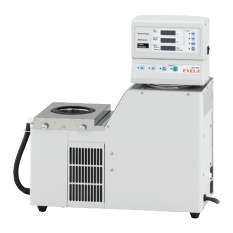
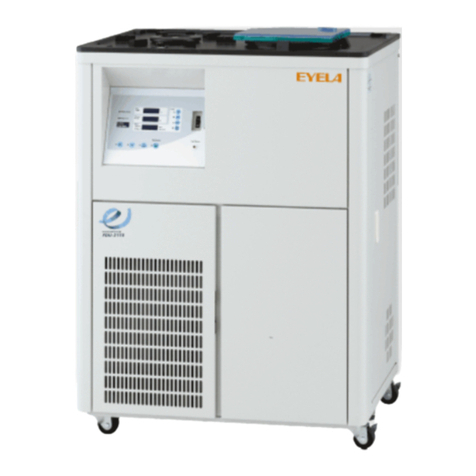
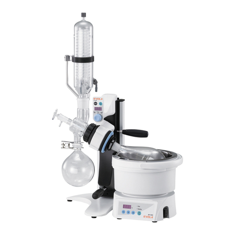
EYELA N-1210 Series User manual

取扱説明書
取扱説明書
Rotary
Vacuum
N-1210 Series
R00
Evaporator 取扱説明書
Instruction Manual
Tokyo Rikakikai Co., Ltd.
This instruction manual is designed to use the product safely with keeping its best
performance.
Please keep this manual in a place easily accessible to every users.
IMPORTANT Be sure to read “Safety precautions” before use.

Important Safety Notice
This unit is not explosion-proof. If you use flammable
substance/sample or organic solvents, take extreme
care not to spill them.
This unit is operated with some parts rotating in the
hot bath because of its function and characteristics.
Glass parts are used in the product and if improperly
handled, glass may break and cause personal injury
or other accidents. Most of such accidents can be
prevented if such danger can be assumed beforehand.
1. Warning Signal Word
To ensure the safety, this manual defines the
information on such matters as requiring particular
care in the safety for each danger and attaches the
alert mark and signal word.
It is recommended to follow the instruction to ensure
the safe use of the product.
We have undertaken thorough verification concerning the possible occurrence of risk when
using the product, but prediction of all and every kind of risk is extremely difficult. Namely,
cautions contained in this manual are not necessarily all of possible risks.
However, if the product is operated according to the procedure described in this manual, the
safe operation and work is ensured. Be sure to pay utmost care during handling of the product
to prevent accident or failure of the product.
Alert mark
Signal word Definition
Wrong handling can cause the possibility of the death or heavy
injury of the user.
Wrong handling can cause the risk of injury of the operator or
physical damages.
Warning
Caution

Contents 5.Operation
5-1 Preparation for operation
5-2 Operating procedures
6.Causes of troubles and solutions
7.Maintenance and check up
7-1 Cleaning and care of the product
7-2 Replacing consumable parts
7-3 Replacing the fuse
8.Disposal of Products
9.After-sales Services
10.Reference material
11.List of Consumable and Replacement parts/
Optional parts
1
2
2
3
6
6
7
8
9
16
18
19
19
19
20
21
22
23
1.For safe operation
2.Product Outline
2-1 Application
2-2 Specifications
2-3 Names of parts
3.Names and functions of control
assembly
3-1 Control panel
3-2 Safety functions
4.Installation
4-1 Installation environment
4-2 Connecting utilities
Thank you very much for purchasing
product.
This instruction manual explains procedures for
installation, operation, troubleshooting, maintenance and
inspection, and disposal of the following Rotary Vacuum
Evaporators:
N-1210B(motorized jack type)
Be sure to carefully read this manual and understand its
description before using this product.
Foreword
When using this product, also refer to the instruction
manual of a water bath used with it.
Be sure to check the types and quantity of parts before installing them.
Package 2
3 Fuse
2 Instruction manual
N-1210
1
1
1 Power cord 1
Package 3
2 Sample flask
3 Receiver flask
4 Rotary joint
5 Capillary feed tube
6 Ball joint clamp
7 Eyela clip
Nozzle set
S
1
1 set
1
1
1
1
1 Condenser 1
Package 1N-1210B
1 Main unit 1
10 Vacuum nozzle set (white)
11 Cooling nozzle set (gray)
12 Screw cap(sealed)
13 Condenser clamp
14 Condenser support bar
15 Thread screw
2 sets
1
-
-
-
-
V
1
1 set
1
1
1
1
1
2 sets
1
1
1
1
2
T
1
1 set
1
1
1
1
1
-
1
-
1
1
2
8 Rotary joint ring
9 Adapter
1
-
11
1
■Main unit ■Cord set
■Glass parts
Rotary joint ring
Ball joint clamp
Eyela clip
Screw cap Threadscrew
2 Vacuum seal 1
3 Hose holder 1
Package Contents
1

For safe operation1
- 1 –
Be cautions, high liquid temperatures bring the rise of burns
Caution
Do not touch the sample flask or the bath when you use the product at high liquid
temperature.
Also take care of the rotation speed of the flask because of possible splashing and
burning depending on the rotation speed.
Do not touch the rotation parts while the flask is rotating
Caution
Do not touch the clip or the specimen flask while the flask is rotating. Your finger
might be caught between protruding parts and grooves of the clip and get injured.
Do not put any objects below the jack
If any objects is caught or placed between the bottom of the jack and the top
surface of the stand base, a malfunction of the unit may occur or the unit may
fall down and cause a personal injury.
Caution
Check the up/down movement range of the jack
While lowering the jack, the flask may strike against the bath and glass may
break or the unit may fall down depending on the inclination angle of the
specimen or the size of the flask used.
Use the manual slide mechanism to adjust the up/down movement range
appropriately on based on the lower limit of the jack.
Caution
※Do not put any
objects below the jack.
Clip
Sample flask
Water Bath
(SB-1300, sold
separately)
Manual slide
Caution Use the thicker type of Rotary Joint for large sample flasks
Use the thicker type of Rotary Joint when 2L or 3L Sample Flask is used. Otherwise
there may be a possibility that the rotary joint is damaged that may cause some injury.

2
- 2 –
2-2 Specifications
This product is a rotary evaporator that is used for
condensation, purification, and fractional distillation of
solutions under reduced pressure.
Vacuum seal
Connection port dia. Nozzle O.D.: 10mm
Type (- glass set)
Rotation motor
Receiver flask
Product name Rotary evaporator
Evaporating capacity
Rev. setting and display
Jack upper/lower limit switch , auto lift-up on power failure
Specimen flask
Volume setting ・digital display
Stepping motor
Rev. speed range 5~280rpm
Jack function Motorized lift + manual extension slide
Teflon seal
※Performance results have been measured at room temperature of 20℃, rated power source voltage.
※Evaporating capacity differs depending on the vacuum, water bath temperature, coolant temperature or other
conditions.
N-1210B -S
Attainable vacuum level
Max.23mL/min(water)
399.9Pa(3mmHg)or less
Condenser
Round flask:1L ball joint S35/20
Pear shaped flask: 1L TS29/38
Horizontal dual spiral condenser
Take care for conditions and
handling of glass parts
Broken or flowed glass parts may result in accidents.
Inspect for damages or flows on glass parts and take
care when handling them.
Caution
※This product is not explosion-proof. Never use the
product for heating solvents under normal pressure or
for chemical reaction.
N-1210B -V N-1210B -T
Performance
Safety function Fuse (2A), motor overload protection circuit
Jack motor DC motor
Power input
Rated power supply AC100V~240V、50/60Hz
Stand base
Weight
Operational envtl temp.
External side(mm)
T-shape base: 490×335mm
2A , 200VA
5~35℃
Approx.13kg
670W×359D×520(750)H
Jack stroke 100mm(motorized lift)+ 130mm(manual extension slide)
Cooling area:0.14㎡
Vertical dual spiral condenser
Cooling area:0.14㎡
Dewar vessel
O.D.110×340H (mm)
(Internal size:91×230mm)
Configuration Standard
Approx.13.5kg
510W×359D×840(1070)H
Approx.14kg
510W×359D×748(978)H
Functions
Product Outline
2-1 Application
Never attempt to modify the product.
Operate the unit for the specified purpose
only.
An electric shock or a malfunction may result if the
product is modified or used for any purposes other
than that specified.
Warning

2-3 Names of parts
N-1210B -S type
Jack up/down key
Capillary feed tube
Continuous
specimen supply
port
Condenser
Ball joint clamp
Eyela clip
Receiving flask
Power switch
Stand base
Driving unit
Jack body
Angle adjusting knob bolt
Manual slide
knob bolt
Slide main body
Hose holder
Vacuum nozzle (white)
Cooling nozzle(gray)
Outlet
(For SB-1300 ・OSB-2200 only)
Fuse
Inlet
Vacuum control
signal connector
Signal connector for
circulating chiller
Sample flask
- 3 -

- 4 -
N-1210B –V type
Jack up/down key
Capillary
Continuous
sample supply
port
Condenser
Ball joint clamp
Eyela clip
Receiver flask
Power switch
Stand base
Driving unit
Jack body
Angle adjusting knob bolt
Manual slide knob bolt
Slide main body
Hose holder
Vacuum nozzle (white)
Cooling nozzle (gray)
Outlet
(For SB-1300・
OSB-2200 only)
Fuse
Inlet
Vacuum control
signal connector
Signal connector for
circulating chiller
Sample flask
Screw plug
Set screw
Condenser clamp
Condenser support bar
Adaptor

- 5 -
N-1210B -T type
Jack up/down key
Capillary feed tube
Continuous
sample supply
port
Cool trap
Ball joint clamp
Eyela clip
Receiver flask
Power switch
Stand base
Driving unit
Jack body
Angle adjusting knob bolt
Manual slide knob bolt
Slide main body
Hose holder
Vacuum nozzle
Outlet
(For SB-1300・
OSB-2200 only)
Fuse
Inlet
Vacuum control signal
connector
Coolant circulating unit
signal connector
Specimen flask
Set screw
Condenser clamp
Condenser support bar
Adaptor

3-1 Control panel
④Rotation control
knob
⑤Rotation lamp
①Power switch
②Run/Stop key
③Speed indicator
No. Name Function
①
Run/Stop key ※1
Speed indicator
Rotation control knob
Alarm lamp
②
③
④
⑤
Press this button to start rotation and press again to stop.
For B type, the jack will automatically go up to the upper limit when rotation
is stopped.
Indicates the rotation speed.
This knob is used to adjust the rotation speed of the sample flask.
Rotation starts at 5rpm at minimum position.
3-2 Safety functions
The product has the following safety functions.
If you encounter any abnormality, take appropriate
measures referring to P.18 “Possible causes of troubles
and solutions”.
- 6 –
Names and functions of control assembly3
Jack up/down key The jack goes up with up arrow key and lowers with down key. The jack keeps
moving while the key is pressed.
Power switch Turning this ON to power on and the switch lamp comes on.
⑥
⑦
Safety function Causes
Fuse The fuse is blown and power is shut off.
Description of operation
Short-circuit occurred or over current flowed
in the power supply circuit.
Motor overload
protection circuit The sample flask rotation axis locked or was
subjected to overload beyond the specification.
Jack upper/lower limit
switch Stops at the jack upper/lower position. Jack upper/lower limit is reached.
Auto lift-up on power
failure ※2
Rotations stops during operation with the
jack lowered and the jack lifts up
automatically.
Power failure occurred or the power switch
was turned OFF.
※2. The jack may not lift completely if it is under load beyond its specification.
Fuse
rpm
Alarm
Rotation
Run
Stop
⑥Alarm lamp ⑦Jack up/down key
Min position
Turns on when an abnormality occurs for rotation control function..
Stops rotation and illuminates the Alarm lamp.
Type B displays [ALr] and lifts the jack.
Rotation lamp The lamp comes on when Run key is pressed and rotation is started and
goes off when rotation is stopped.
※1. Please do not run empty, because rotating without placing the glass set can result into defective rotation.

4-1 Installation environment
Select a place that meets the conditions below for
installing this product:
- 7 –
Installation4
Never install the product in a
potentially hazardous atmosphere.
The product is not explosion-proof. Use in a
potentially hazardous atmosphere may cause a fire
or other accidents.
Warning
●A place free of flammable gas, liquid, or solid
materials in the vicinity of the product.
●A place where the ambient temperature can be kept
within a range of 5~35℃.
●A place free from condensation
●A place with less humidity and free from splashing
water
●A place with minimum dust。
●A place out of/away from direct sunshine
●An airy or well-ventilated place
●A level, stable, and firm place

- 8 -
4-2 Connecting utilities
Warning
Connect the ground wire correctly.
Never connect the ground wire to a gas pipe or a
water pipe to avoid an electrical shock .
Warning
Do not use the branching socket or
table tap.
Over-current may cause cable burn, fire.
Power supply to connect
Voltage Capacity
AC230V 8A
* At this time, do not connect the power plug.
* When connecting to the power supply, do not
use a branch socket or table tap.
* Make sure that the sleeve of power cord is not
damaged. Such damage may cause electric
shock.
* Use attached power cord. Otherwise, lack of
capacity, etc. may cause fire or electric shock.
(1) Check the product type as well as the voltage, phase,
and capacity of power supply to be connected.
Power supply to be connected to the product is as
shown in the right.
(2) Check the receptacle of installation place.
Prepare an outlet with a ground terminal.
Specification of Power Cord
Warning
Confirm the voltage, phase, capacity,
and the type of receptacle of power
supply.
Wrong connection of power supply may cause fire or
electric shock
Name Code No
Cable Cros-sectional area of
cable(AWG) Region
covered
Length Thickness
(Outer dia.)
230V Power Cord B Type 245373 Approx.2.0m Approx.6.9mm 1.25mm2(AWG16) India
230V Power Cord C Type 245372 Approx.2.0m Approx.6.9mm 1.25mm2(AWG16) Europe
230V Power Cord O Type 245371 Approx.2.0m Approx.6.9mm 1.25mm2(AWG16) Oceania

- 9 -
1. Raise the jack
(1) While holding the top surface of the “jack body”,
(2) Remove the “PP band” that ties around the stand
base and the driver together.
The jack body will go up to the upper end with the
spring force.
※Note that the lifting force is stronger.
5-1 Preparation for operation
Operation
5
Be careful for jumping of the jack.
This jack is always under a lifting force.
When you release the lock, be sure to put your hand
on the jack.
Caution
Be sure to raise the jack before
setting glass parts.
First raise the jack before setting glass parts. If the
jack is raised during setting work, a personal injury
may result.
Caution
Be careful when handling the glass parts
Glass parts are easily damaged.
Handle them with care.
Caution
PP band
Jack body Driving unit
Stand base

- 10 –
2. Installing the rotary joint
(1) Fit the rotary joint ring over the rotary joint.
(2) With the flask removal screw installed on the drive
body, insert the rotary joint and the rotary joint
ring altogether into the drive body.
(3) Securely insert the rotary joint until it is hooked on
the sleeve pin inside the drive assembly.
Set the rotary joint ring so that it will hook on the
inside of the flask removal screw.
※If the rotary joint is not inserted completely,
imperfect rotation, dropping of the sample flask,
or vacuum leakage may result.
(4) When you want to remove the rotary joint, turn the
flask removal screw anticlockwise, and then pull
out the rotary joint while allowing the rotary joint
ring to touch the joint.
3. Installation of the vacuum seal
The vacuum seal is an important part for the
performance of the evaporator. Take sufficient
care handling it.
(1) Holding the rotary joint so that the side on the
vacuum seal spring and the O ring are visible
toward the driver body and insert into the rotary
joint at the right angle into the housing.
※Be sure to install the rotary joint before
installing the vacuum seal.
※Verify the direction of the seal faces.
※Take care not to damage the seal lip during
washing and thoroughly dry it after washing.
※When storing, put the product in a plastic bag
to protect from external pressures.
※When you use the vacuum seal for the first time,
the unit may present an insufficient rotation
and cannot obtain sudden high rotation because
of initial tightening of the seal lip . In this case,
start with a low rotation speed and gradually
increase it.
※The vacuum seal is a consumable part.
Rotary joint ring
Rotary joint
Vacuum seal
O-ring
Spring
Rotary joint
Drive body
Housing
Sleeve pin
Flask removal screw
Rotary joint ring
Drive body
Seal lip
※When 2L or 3L size of the sample flask is used,
use the thicker type of Rotary Joint ( Option )
should be used.

- 11 –
(1) Allow the condenser to tightly touch the vacuum
seal in the housing and then tighten with the set
screw.
When you have tightened to some extent, re-
tighten both the set screw and the condenser at the
same time and position the receiver flask so that its
fixing opening faces down.
(2) Fix the receiver flask to the condenser with the
ball joint clamp.
For S type
Nozzle set Nozzle packing
(3) Fix the sample flask to the rotary joint with the
Eyela clip.
(4) Gently insert the capillary into the condensers.
(5) Install two cooling nozzles (gray) and a vacuum
nozzle (white) to the condenser.
Make sure that the nozzle packing sits in the
groove before installation.
(6) Follow the procedures above in reverse order to
remove.
Condenser
Capillary feed
tube
Coolant nozzle(gray)
Vacuum nozzle (white) Set screw
Housing
Rotary joint
Eyela clip
Sample flask
Receiver flask
Ball joint clamp
4. Installing the cooler and a flask
If you want to use a glass trap ball, perform steps
in P.15 “8. Adjusting position for a glass trap ball”
before performing the following procedures.
Caution Be sure to raise the jack before
setting glass parts.
First raise the jack before setting glass parts. If the
jack is raised during setting work, a personal injury
may result.
Caution
Take care for condition and
handling of glass parts
Broken or flowed glass parts may lead to accidents.
Inspect for damage or flows on the glass parts and
take care when handling them.

For V Type
- 12 –
Set screw
Housing
Receiver flask
Ball joint clamp
Set screw
Caution Be sure to raise the jack before
setting glass parts.
First raise the jack before setting glass parts. If
the jack is raised during setting work, a personal
injury may result.
Caution
Take care for condition and
handling of glass parts
Broken or flowed glass parts may result in accidents.
Inspect for damage or flows on the glass parts and
take care when handling them.
(1) Fix the condenser support bar into the hole at the back
of the unit using the set screw. (Adjust its position
after setting glass parts.)
(2) Allow the adopter to tightly contact against the
vacuum seal in the housing and then tighten with the
cap screw.
When you have tighten to some extent, re-tighten both
the cap screw and the adopter at the same time and
position the receiver flask so that its fixing opening
faces downward.
(3) Install the cooler to the adaptor.
(4) Install the cooler clamp.
Adjust the cooler support bar and the cooler positions
and fix with the set screw.
(5) Fix the receiver flask to the cooler with the ball
joint clamp.
(6) Fix the specimen flask to the rotary joint with the
Eyela clip.
(7) Gently insert the capillary into the adopter
(8) Install two coolant nozzles (gray), a vacuum nozzle
(white) and screw plug to the cooler.
Make sure that the nozzle packing sits in the groove
before installation.
(9) Follow the procedures above in the reversed order
to remove.
Cooler
Capillary feed tube
Coolant nozzle(gray)
Vacuum nozzle (white)
Rotary joint
Eyela clip
Specimen flask
Nozzle set Nozzle packing
Screw plug
Cooler clamp
Cooler support bar
Adopter

For T Type
- 13 –
Cool trap
Capillary
feed tube
Set screw
Housing
Rotary joint
Eyela clip
Sample flask
Receiver flask
Ball joint clamp
Set screw
Condenser support bar
Condenser clamp
(1) Fix the condenser support bar into the hole at the
back of the unit using the set screw. (Adjust its
position after setting glass parts.)
(2) Allow the adaptor to tightly contact against the
vacuum seal in the housing and then tighten with
the set screw.
When you have tightened to some extent, re-
tighten both the set screw and the adapter at the
same time and position the receiver flask so that
its fixing opening faces down.
(3) Install the condenser to the adaptor.
(4) Install the condenser clamp.
Adjust the condenser support bar and the
condenser positions and fix with the set screw.
(5) Fix the receiver flask to the condenser with the
ball joint clamp.
(6) Fix the sample flask to the rotary joint with the
Eyela clip.
(7) Gently insert the capillary into the condenser.
(8) Install the vacuum nozzle to the cooler.
Make sure that the nozzle packing sits in the
groove before installation.
(9) Follow the procedures above in reverse order to
remove.
Nozzle set Nozzle packing
Vacuum nozzle
Adaptor
Caution Be sure to raise the jack before
setting glass parts.
First raise the jack before setting glass parts. If the
jack is raised during setting work, a personal injury
may result.
Caution
Take care for conditions and
handling of glass parts
Broken or flowed glass parts may result in accidents.
Inspect for damages or flows on glass parts and take
care when handling them.

- 14 –
5. Adjusting the angle of the drive body
Adjust the angle of the drive body
while holding the condenser with a
hand.
When you loosen the angle adjusting knob bolt, the
drive may suddenly incline from the weight of the
cooler or sample flask and fall down and you might
get injured by the broken glass.
Caution
(1) Lift the jack body.
(2) Loosen the angle adjusting knob bolt to adjust the
angle while supporting the condenser with a hand.
(3) Check the vertical position of the jack and its
position relative to the bath and then securely
tighten the angle adjusting knob bolt.
6. Connecting the vacuum hose and
the coolant hose
(1) Insert the hose holder into the groove on the right
side of the jack body.
(2) Connect the condenser vacuum nozzle and the
suction port of your vacuum unit using a vacuum
hose through the hose holder.
※The vacuum hose for connecting to the vacuum
unit is not included. Check the size of the
connection nozzle and prepare a correct hose.
※Take care not to apply excessive force when
connecting the vacuum hose. The nozzle is
made of resin and may be damaged if it is
subject to an excessive force.
(3) Connect the cooler coolant nozzle and the
circulation port of you circulating chiller using a
connecting hose through the hose holder.
※The connecting hose is not included. Check the
capacity of your circulation unit and the size of
the connection nozzle and prepare a correct
hose.
Vacuum nozzle (white)
Cooling nozzle inlet
Cooling nozzle outlet
Vacuum nozzle
Cooling nozzle inlet
Cooling nozzle outlet
Vacuum nozzle
LOCK
FREE
Angle adjusting knob bolt
Hose holder
Right side of
the jack body

- 15 –
8. Adjusting the position of the glass trap ball
(Adjusting the manual slide)
Use both hands to lift the manual
slide slowly.
After loosening the manual slide knob bolt, the
drive body may fall down, glass may break and
result in a personal injury if you try to lift the body
suddenly.
Caution
You can adjust the manual slide assembly to a
position appropriate for the trap ball or specimen
flask sizes.
Follow the procedures below to install a trap ball
before installing the cooler.
7. Connecting the power cord
(1) Insert the power cord plug into the inlet on the
back of the stand base.
(2) Make sure that the power switch is turned OFF
and then insert the power plug into an outlet.
Be sure to lower the manual slide
slowly while supporting the driving
assembly with a hand.
When you loosen the manual slide knob bolt
suddenly, the drive may suddenly lower from the
weight of the cooler or sample flask causing the
glass to break from the shock and you might get
injured by the broken glass.
Caution
(1) Loosen the manual slide knob bolt, hold the drive
body with both hands and slowly lift it and then
tighten the manual slide knob bolt.
※Remove the cooler before attempting these
procedures.
※The internal tightening plate may come if you
loosen the manual slide knob excessively. If it
occurs, lower the slide body, align the knob
bolt with the internal plate and then tighten the
knob.
(2) Install the trap ball and the specimen flask using
the Eyela clamps.
(3) Set the bath, support the lower part of the front of
the drive with one hand, gently loosen the manual
slide knob bolt to adjust the height.
※When you loosen the manual slide knob bolt
suddenly, the drive may suddenly lower from
the weight of itself causing the glass from
shocks and you might be injured with broken
glass.
Plug Inlet
LOCK
FREE
Manual slide knob bolt
Drive body
Slide body
Trap bulb
Sample flask
Eyela clip
Eyela clip

5-2 Operating procedures
Stop operating the unit if you notice
any abnormal conditions.
If you notice any abnormal condition, immediately
turn the power switch OFF and refer to the section
“Causes of troubles and countermeasures”.
Caution
Never touch the sample flask or the
bath during condensation.
The bath and the specimen flask will be hot during
condensation and there is a danger of burning.
Caution
- 16 –
Caution
Never spill sample on the unit.
If any sample is spilt on the body or on the water
bath, immediately wipe it out.
Some types of sample may be ignited with heat of
the body or the water bath.
Warning
Jack up/down key
Continuous
sample feeding
port
Capillary feed tube
Water bath
(SB-1300 type)
Sample flask
Condenser
(S-type)
Rotation control knob
Power switch
Continuous
sample
feeding port
Capillary
feed tube
Continuous
sample
feeding port
Capillary
feed tube
Condenser
(V-type)Condenser
(T-type)
Receiver flask
Take care for conditions and
handling of glass parts
Broken or flowed glass parts may result in accidents.
Inspect for damages or flows on glass parts and take
care when handling them.

- 17 –
(1) Set the temperature for the water bath and coolant.
(Refer to the operation manuals of the water bath
and the cooling circulator unit for operating
procedures of them.)
(2) Turn the power switch ON.
(3) Close the capillary cock. Turn it so that the blue
mark will face you.
※Apply some vacuum grease before operating the
unit.
(4) Supply or set samples with the procedures (I)or
(II)below.
(I)To supply samples continuously
①Connect the continuous sample feed port and the
sample container with a tube.
②Gently lower the jack so that the sample flask will
be lowered into the heating bath.
③Press Run/Stop key and turn the rotation control
knob to set the number of rotations you want.
④Start the vacuum unit to depressurized inside the
evaporator.
⑤Align the capillary cock with the continuous
sample feed port (blue mark points downward) and
supply sample.
Operation
Stopping operation
Procedures after operations
(1) Press Run/Stop key to stop rotation, gently raise
the jack and then take out the sample flask.
※Will automatically go up and stop.
(2) Open the capillary cock (blue mark points upward)
and return the internal pressure to the normal
pressure.
(3) Stop the vacuum unit.
(4) If you are not going to set samples, stop operation
of all of the cooling circulator and the water bath.
※Note that the heating bath and the sample flask are
hot for some time after completion of
concentration and may cause burning.
(5)To remove the sample flask, remove the Eyela clip,
turn the flask removal screw as shown in the right
diagram, apply the rotary joint to the mouth of the
sample flask and turn it.
If you are not going to use the product for a long time,
turn the power switch OFF, and remove the power
plug out of the AC outlet.
(II)Not to supply sample continuously
①Remove the sample flask and directly put sample
in it.
②Press Run/Stop key, turn the rotation control knob
to set to the number of rotations you want.
③Gently lower the jack and put the sample flask in
the heating bath.
④Activate the vacuum unit to depressurized inside
the evaporator.
※If the rotary joint and the sample flask stick
together and cannot be separated, remove them
altogether first and then warm the flask and
remove.
(6) Remove the ball joint clip while supporting the
receiver flask from bottom.
Sample flask
Rotary joint ring
Flask removal
screw
Blue part
Blue part
Continuous sample
feed port
During concentration
During continuous
supply feed When vacuum
released
Blue part
This manual suits for next models
3
Table of contents
Other EYELA Laboratory Equipment manuals
Popular Laboratory Equipment manuals by other brands

Boekel
Boekel Slide Moat 240000 operating instructions

Parr Instrument
Parr Instrument 4560 Operating instructions manual

Biuged Laboratory Instruments
Biuged Laboratory Instruments BGD 626 instruction manual

PASCO
PASCO h/e Apparatus instruction manual

Sartorius Stedim Biotech
Sartorius Stedim Biotech MD8 airscan operating instructions

TESTO
TESTO 868s instruction manual