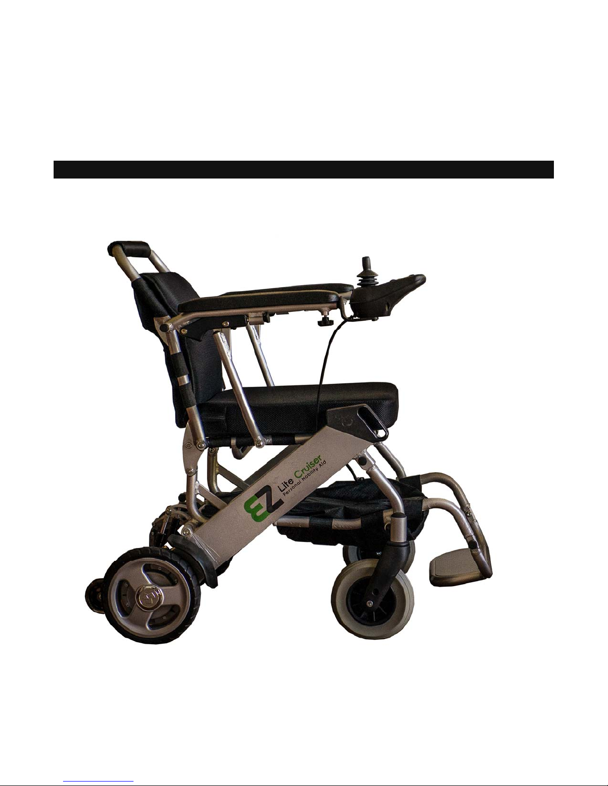
Introduction to the EZ Lite Cruiser
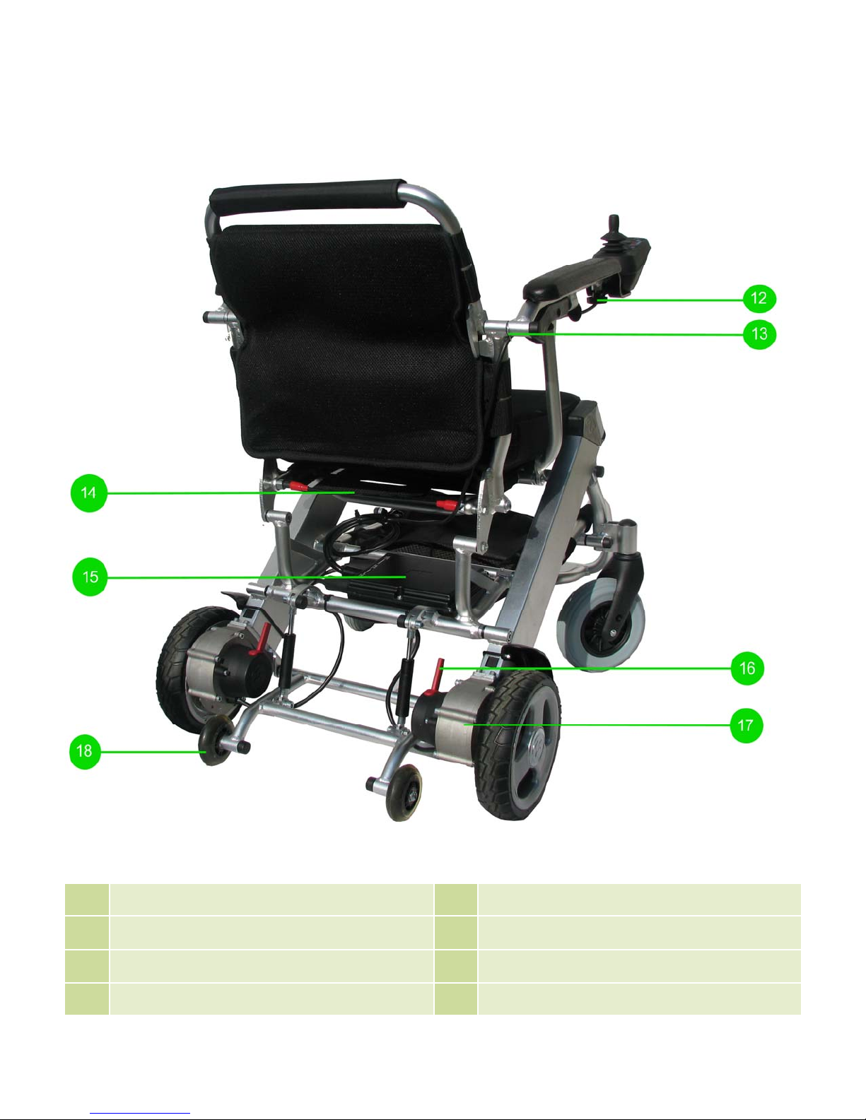
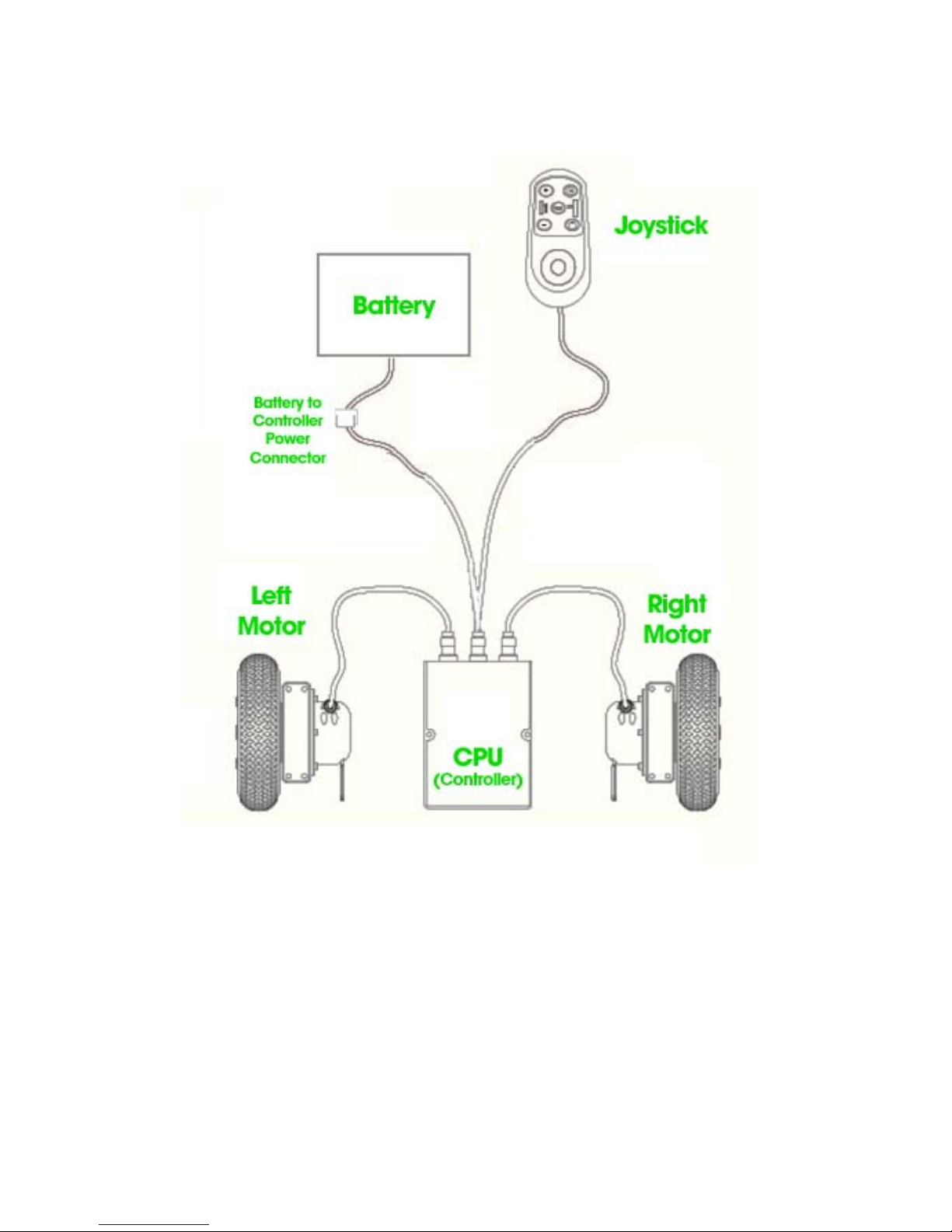
The EZ Lite Cruiser is a Light Weight Power Wheelchair with Brushless Hub Motors. It uses a lithium ion
battery as a source of power. The battery connects underneath the seat, from the CPU controller compo-
nent.
The EZ Lite Cruiser comes with one lithium ion battery as the power source. It operates by using the con-
trol module to deliver all programmed commands to the brushless motors located on the rear wheels.
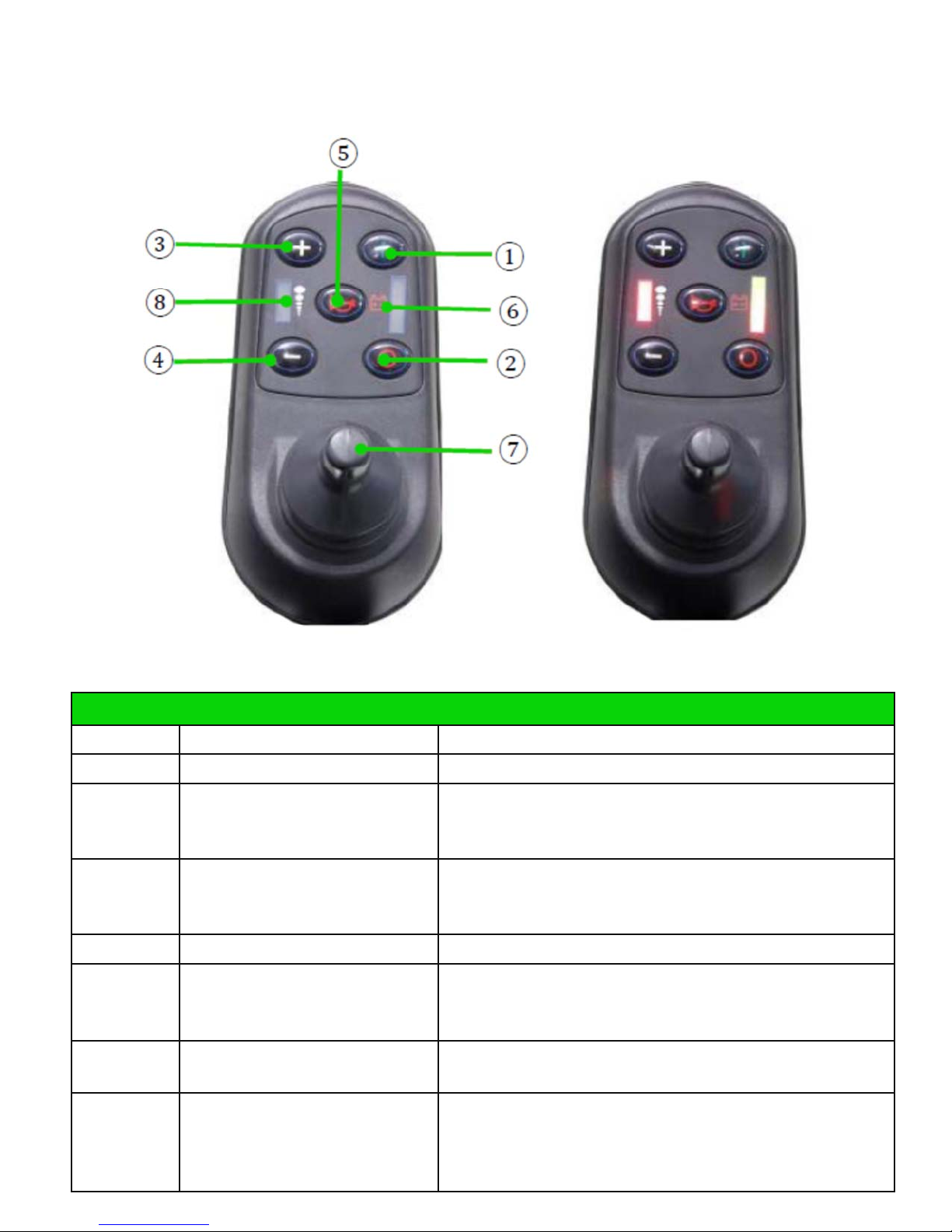
The joystick component of the control system carries out directional commands, as well as maintaining
the speed and power of the EZ Lite Cruiser.
The charging port for the EZ Lite Cruiser is located on the front (facing head on) of the joystick compo-
nent. The standard wall charger included with the EZ Lite Cruiser will have a matching connector which
can only be inserted one way. Please ensure proper alignment of the connector when plugging it in, and
power off the device when charging.
The main feature of the EZ Lite Cruiser is its ability to fold to a compact space. Using the wire located at
the back of the chair, near the base of the seat, you can fold the chair down. When standing behind the
EZ Lite Cruiser, pull on the wire outward straight on to release the locking mechanisms (spring loaded
pins) from each side of the main frame section.
By pushing downward on the top of the unfolded back support and the EZ Lite Cruiser will collapse on
itself. Notice the top half of the back support can be folded inward. When folding, first keep the top half
of the back support unfolded while pushing down, to expedite the folding overall. When the EZ Lite Cruis-
er is folded, then fold the top half of the back support inward toward the seat cushion.
When folded, the EZ Lite Cruiser can maintain a balanced position and be stood upright on the rear
wheels. It is kept balanced by the metal rods that act primarily to keep the top half of the back support
unfolded. Notice when you fold down the top half of the back support, on each side there are metal rods
protruding out. When the EZ Lite Cruiser is folded, it can stand up on the rear wheels and use those rods
to keep it balanced.
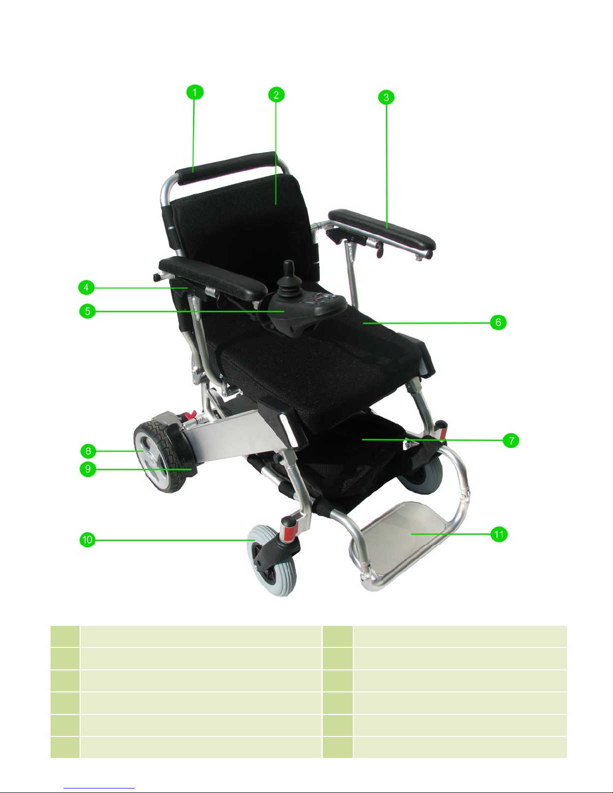
The front wheels of the EZ Lite Cruiser act in the same manner as caster wheels commonly found on
wheelchairs. They rotate completely depending on the direction being driven—forward or reverse. Allow
for adequate space for these to turn when changing direction.
The motors on the rear wheels have electromagnetic locks, by way of levers) to allow or prevent the rear
wheels from moving in free-wheel motion. When these levers are flipped forward towards the chair, the
electromagnetic locks will be disengaged and the wheels can roll freely. When the levers are flipped
backward towards the person standing behind the chair, the locks will be engaged and the rear wheels
will only move in the powered mode.
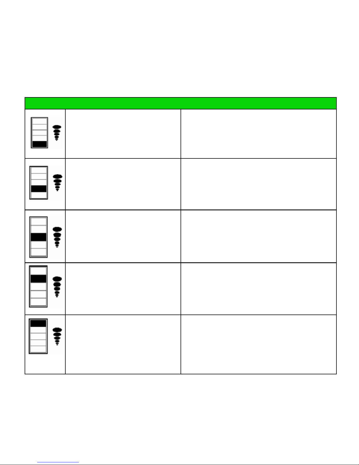
While the device is powered on, the wheels will always be locked. If the device is used in the powered
mode while the electromagnetic lock is disengaged, a fault indicator on the joystick component of the con-
troller system will indicate that the electromagnetic lock is disengaged.