Ezee-On 4600 DISC User manual

Ezee-On
MODEL 4600 DISC
HEAVY DUTY TANDEM
3 SECTION FRAME
OWNER'S MANUAL
c/w
ASSEMBLY INSTRUCTIONS - (for S/N 51376 and later)
and
Parts List - (for all Serial Numbers)
Manufactured Vegreville, Alberta
by Ezee-On Manufacturing Canada
721F
Printed in Canada

INTRODUCTION
Thank you for deciding to purchase this Ezee-On product. In addition to having traditional Ezee-On reliable and durable disc, your new
implement incorporates a number of operational and safety features. We urge you to familiarize yourself with the operation and maintenance
of your implement by reading this manual carefully.
Remember that it is the responsibility of the operator to ensure that the implement is field ready. However, should you encounter a problem,
please contact your dealer immediately.
This manual contains the following:
- initial setup instructions
- operational (field) instructions
- parts listing for this implement
READ THIS BOOK CAREFULLY TO INSURE THAT YOUR NEW DISC IS ASSEMBLED AND ADJUSTED CORRECTLY.
RIGHT and LEFT is determined by standing behind the machine and facing FORWARD in the direction of travel.
This symbol is used to identify safety messages. When you see this symbol, read the safety message carefully.
EZEE-ON RESERVES THE RIGHT TO MAKE CHANGES IN MODEL OR SPECIFICATIONS WITHOUT ANY OBLIGATION AS TO THE
REPLACEMENT OR MODIFICATIONS IN PREVIOUS MACHINES.
INDEX
PAGE
Safety
Specifications
General Operating Instructions
Adjustments
Maintenance
Trouble Shooting
Assembly Instructions
2
5
6
12
15
18
21
Page 1

Page 2
SAFETY RECOMMENDATIONS
WATCH FOR THIS SYMBOL. IT IDENTIFIES IMPORTANT SAFETY MESSAGES. WHEN YOU SEE THIS SYMBOL, READ THIS SAFETY MESSAGE
CAREFULLY.
GENERAL SAFETY
1. Never allow anyone to ride on the tractor drawbar, or on the disc. The person(s) riding may fall and be seriously or fatally injured.
2. Disc should be operated ONLY by persons responsible and qualified to do so.
3. Never allow anyone to climb or play on the tractor or disc. They may fall and be seriously injured.
4. Follow all safety precautions in your tractor manual.
5. Keep a First Aid Kit in the tractor at all times.
ASSEMBLY SAFETY
1. When assembling disc, use aligning punch to line up holes. Keep fingers out of holes. Any sudden movement of heavy components will severely
injure or sever your fingers.
2. Use adequate manpower or hoist to lift the heavy components into place. Attempting to lift heavy components by yourself could cause serious
injury.
3. Be sure all bolts and hydraulic fittings are tight, and all cotter pins are installed in the slotted nuts and pins.
4. Support the main and wing frames securely before assembling the components. Inadequate support may result in the heavy components falling
and causing serious injury to you or person(s) nearby.
5. Be sure all wheel bolts are checked for tightness during initial transport or when first discing. Loose wheel bolts may result in the wheel falling
off, causing serious damage to the disc and may cause serious injury to the operator or person(s) nearby.
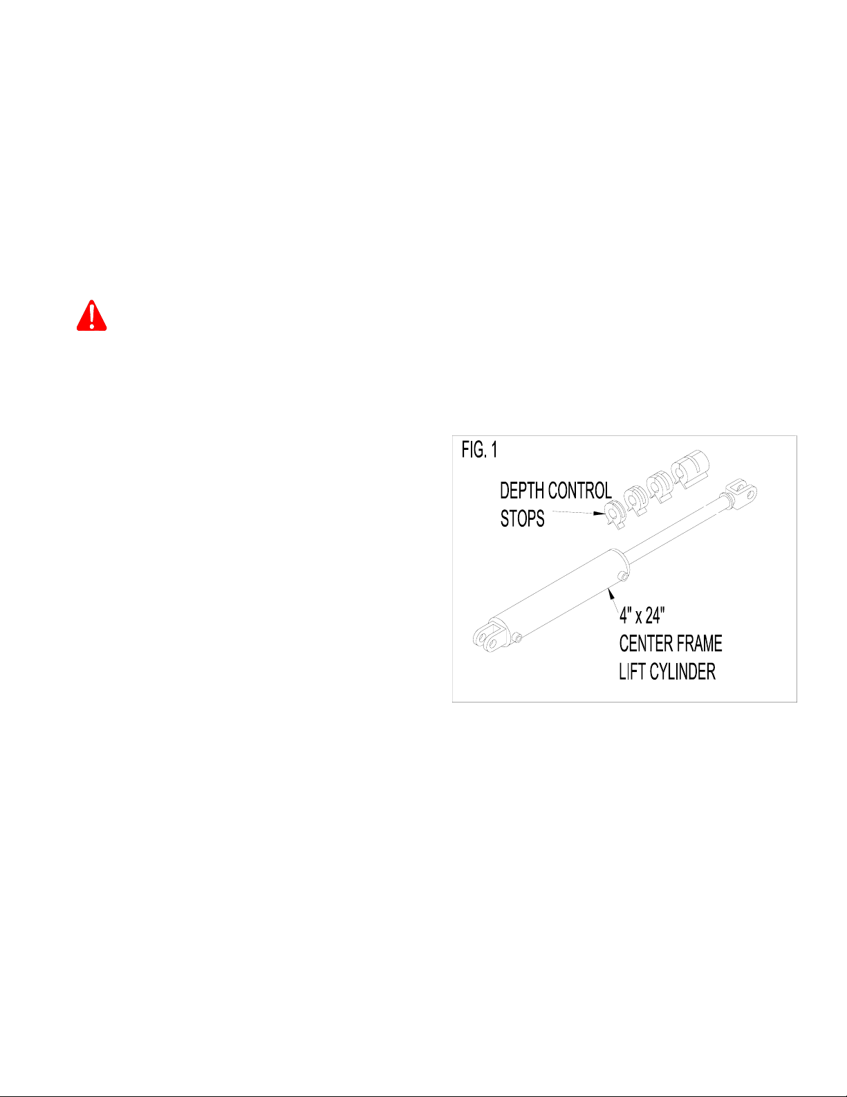
6. To fill the wing lift cylinders with hydraulic fluid, remove the pin from the shaft end of each wing lift cylinder and pump fluid into the cylinders.
Extend and contract the cylinders until they are completely filled with hydraulic fluid. The wings will free-fall if the cylinders are not completely
filled with fluid, resulting in serious damage to machine or serious injury or death to person(s) nearby.
7. Do not raise or lower the main or wing frames until all components are securely tightened. Loose components will cause serious damage to the
disc and serious injury or death to you and person(s) nearby if the main or wing frames fell.
8. Hydraulic oil escaping under pressure has sufficient force to cause serious injury. Relieve pressure in all hydraulic components before
disconnecting any hydraulic components. Before applying pressure to hydraulic system, be sure all connections are tight and components are
not damaged. If injured by escaping hydraulic fluid, see a medical doctor immediately.
9. When attaching gang assemblies, wear protective gloves to prevent injury from cutting edges of blades.
10. Before applying pressure to the hydraulic system, be sure all connections are tight and the components are not damaged.
11. Wings will free fall if wing cylinder is not full of oil causing serious damage to machine or serious injury or death to person(s) nearby.
12. If hydraulic cylinder shafts are unpinned and cycled to fill the cylinders with oil, they can be seriously damaged if clevis of shaft strikes rockshaft
arm or wing cylinder lug.
13. Do not stand under folded wings when working on disc. If hydraulic system failed or if hydraulic lever was accidentally operated, wings may fall
resulting in serious injury or death to person(s) near disc.
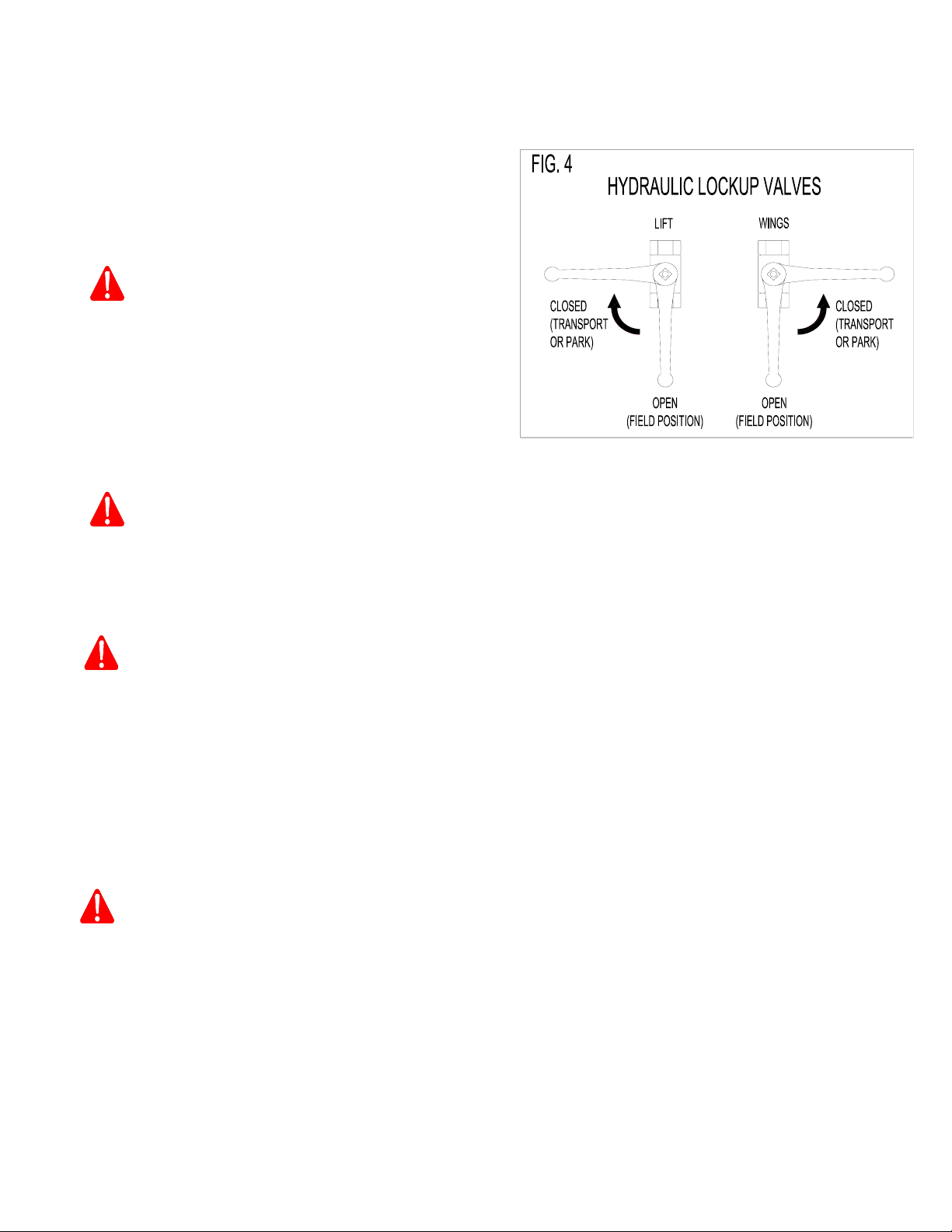
14. When assembling gangs besure adequate support is placed under main frame and wing frames. Do not use lock out valves as safety device to
prevent frame from falling. If any hydraulic component failed, disc could drop causing serious injury or death to person(s) nearby.

Page 3
MAINTENANCE SAFETY
1. Do not loosen or disassemble hydraulic components when there is pressure within those components. Hydraulic components under pressure
may cause parts and hydraulic fluid to fly out at a high velocity, which could cause serious injury. Always relieve the pressure in the hydraulic
system before making adjustments to the hydraulic system. If injured by escaping hydraulic fluid, see a medical doctor immediately.
2. Check all hydraulic hoses periodically for signs of ruptures and leaks. Always use wood or cardboard as a backstop, and wear gloves and eye
protection when searching the hydraulic system for leaks. Spurting hydraulic fluid can cause injury if it penetrates the skin or the eyes. If injured
by escaping hydraulic fluid, see a medical doctor immediately.
3. Always relieve the pressure in the hydraulic system when the disc is not being operated.
4. Always permit parts which contain hot fluid to cool to a safe temperature before handling or disconnecting these parts.
5. Always wear safety glasses or goggles and gloves when working on the hydraulic system.
6. To fill wing lift cylinder with hydraulic oil, extend and contract cylinder within slot on wing until cylinders are completely filled with oil. Do not fold
wings until cylinders are completely filled, wings will free fall if cylinders are not filled with oil, causing serious damage to machine or serious
injury or death to person(s) nearby.
7. Lower the disc to the ground when servicing or making adjustments. If the disc must be serviced in the raised position, place blocks under frame.
Do not rely on hydraulics lock up valves as a safety device. If the hydraulic system failed, or if the hydraulic lever was accidentally operated,
the disc could drop.
8. Do not lubricate disc while it is in motion. You may fall in front of disc and be seriously or fatally injured.
9. Always place all tractor controls in neutral and lock brakes
when hitching disc to tractor. Tractor could roll backwards
when hitching disc.
10. If wing lift cylinder(s) or wing lift hydraulic hoses are removed when wings are folded into transport position, always install a safety chain between
each wing frame and main frame to prevent wings from falling. If wing(s) fell, serious injury or death could occur to person(s) nearby and machine
would be damaged severely.
11. When inflating tires use a clip-on chuck and air hose extension which will allow operator to stand clear of tire and wheel assembly. Do not stand
in front of or over tire when inflating. Exploding tire and wheel parts can cause serious injury or death.
TRANSPORT SAFETY
1. When trailing the disc over public roads, use the SMV emblem and warning light for protection of tractor and other motor vehicle operators. Check
local laws for width and height maximums.
2. When transporting disc always place both hydraulic lock up valves in “closed” position. See Section 6 of Operating Instructions on page 6. If
hydraulic lever was accidentally operated the disc could drop or wings could fall causing serious injury or death to operator or person(s) nearby.
3. Do not exceed 10 mph (16 km/h) when transporting the disc on smooth surfaces. Reduce speed when transporting on rough surfaces. Excessive
speed could cause loss of tractor control and damage to disc and tractor. Do not transport the disc with any other vehicle except a tractor.
4. When transporting disc always install the complete package of depth control stops - 17" long (431.8 mm) on shaft of centre frame cylinder. If
any component of hydraulic system failed disc could drop and causing serious injury or death to operator or person(s) near by.

Page 4
TRANSPORT SAFETY CONTINUED:
5. When transporting the disc with the wings folded (UP), be sure there is sufficient clearance under all power lines and other overhead obstructions.
Serious injury or death can result from contact with electrical lines. Use care to avoid contact with electrical lines when moving or operating the
disc. Refer to specification chart on page 5 for approximate transport height for your machine.
6. Always attach a safety chain to the tractor drawbar and the
disc hitch before transporting the disc. The safety chain will
help control disc should it accidently separate from the
drawbar. Use a chain with a strength rating greater than the
gross weight of the towed machine. Serious damage and
injury could result from the disc separating from the tractor
drawbar.
7. Check all reflectors and visibility and cleanliness before transporting the disc. It is important that the reflectors are clean and visible, especially
during the evening hours.
8. Regulate your speed on hillsides and curves when transporting
the disc. Loss of tractor control could result in serious damage
to the disc and possible serious injury or death to you or
person(s) nearby.
9. Never allow anyone to ride on drawbar of the tractor or on the disc. The person riding may fall and be seriously injured.
OPERATION SAFETY
1. Be sure person(s) are standing clear before starting or moving the tractor and disc.
2. Only one (1) person (the operator) should be permitted on the tractor when the disc is in operation, and he/she should be familiar with repair
procedures and temporary first aid treatment.
3. Never stand between the tractor and disc when hitching disc to the tractor UNLESS all tractor controls are in neutral and the park brake is set.
The tractor could roll backwards which could result in serious injury or death to you or persons nearby.
4. When operating on hillsides, use extreme care. The tractor may tip over if it strikes a hole, ditch or other irregularity.
5. To avoid personal injury or death, always stay clear of the folding wings when they are being raised, lowered or in the folded position. If the
hydraulic system failed, or if the hydraulic lever was accidentally operated, the wings could drop, resulting in serious injury or death to you or
person(s) nearby.
6. Do not stand under wing while wing is being raised or lowered. If any components of hydraulic system should fail, or if hydraulic lever should
accidentally be operated, wing could drop causing serious injury or death .
7. Always relieve the pressure in hydraulic system and close both hydraulic lockup valves when the disc is not being used.
SAFETY DECALS
1. Keep all decals clean and in good condition to provide you with a constant reminder of safe operating procedures.
2. Replace any destroyed, missing or illegible decals.
STORAGE
1. Wings may unfold due to thermal expansion of hydraulic oil causing damage to disc, property or severe injury or death to person(s) nearby.
Release pressure in all cylinders then close hydraulic lockup valves before unhitching from tractor or when parking with tractor.

Page 5
SPECIFICATIONS
MODEL
WING
WIDTH
BLADE
SPACING
APPROX.
CUTTING
WIDTH
NO. OF
BLADES
NO. OF
GANG
BEARINGS
GANG BEARING
TYPE
WING LIFT CYLINDER APPROX.
TRANSPORT
WIDTH
APPROX.
TRANSPORT
HEIGHT
STD. NO. SIZE
4600 - 66SN
4600 - 70SN
4600 - 74N
4600 - 86N
4600 - 94W
4600 - 102W
4600 - 106W
4600 - 110W
4600 - 58SN
4600 - 62SN
4600 - 66N
4600 - 74N
4600 - 82W
4600 - 90W
4600 - 94W
4600 - 98W
4600 - 50SN
4600 - 54SN
4600 - 58N
4600 - 66N
4600 - 74W
4600 - 78W
4600 - 82W
4600 - 86W
Super Narrow
Super Narrow
Narrow
Narrow
Wide
Wide
Wide
Wide
Super Narrow
Super Narrow
Narrow
Narrow
Wide
Wide
Wide
Wide
Super Narrow
Super Narrow
Narrow
Narrow
Wide
Wide
Wide
Wide
9" (230 mm)
9" (230 mm)
9" (230 mm)
9" (230 mm)
9" (230 mm)
9" (230 mm)
9" (230 mm)
9" (230 mm)
10-1/2" (267 mm)
10-1/2" (267 mm)
10-1/2" (267 mm)
10-1/2" (267 mm)
10-1/2" (267 mm)
10-1/2" (267 mm)
10-1/2" (267 mm)
10-1/2" (267 mm)
12" (305 mm)
12" (305 mm)
12" (305 mm)
12" (305 mm)
12" (305 mm)
12" (305 mm)
12" (305 mm)
12" (305 mm)
24-1/2' (7.5 m)
26' (7.90m)
28' (8.53 m)
32-1/2' (9.90m)
35-1/2' (10.82 m)
38-1/2' (11.73 m)
40' (12.19 m)
41-1/2' (12.64 m)
25' (7.60 m)
26-1/2' (8.10 m)
29' (8.83 m)
32' (9.75 m)
35-1/2' (10.82 m)
38-1/2' (11.73 m)
40-1/2' (12.34 m)
42' (12.80 m)
24' (7.30 m)
26' (7.90 m)
28-1/2' (8.68 m)
32-1/2' (9.90 m)
36-1/2' (11.12 m)
38-1/2' (11.73 m)
40-1/2' (12.34 m)
43' (13.10 m)
66
70
74
86
94
102
106
110
58
62
66
74
82
90
94
98
50
54
58
66
74
78
82
86
20
20
22
24
28
32
34
34
20
20
22
24
28
32
34
34
20
20
22
24
26
28
32
34
T2-215
T2-215
T2-215
T2-215
T2-215
T2-215
T2-215
T2-215
T2-215
T2-215
T2-215
T2-215
T2-215
T2-215
T2-215
T2-215
T2-215
T2-215
T2-215
T2-215
T2-215
T2-215
T2-215
T2-215
2
2
2
2
4
4
4
4
2
2
2
2
4
4
4
4
2
2
2
2
4
4
4
4
4" x 36"
4" x 36"
5" x 36"
5" x 36"
5" x 36"
5" x 36"
5" x 36"
5" x 36"
4" x 36"
4" x 36"
5" x 36"
5" x 36"
5" x 36"
5" x 36"
5" x 36"
5" x 36"
4" x 36"
4" x 36"
5" x 36"
5" x 36"
5" x 36"
5" x 36"
5" x 36"
5" x 36"
17'0" (5.18 m)
17'0" (5.18 m)
17'0" (5.18 m)
17'0" (5.18 m)
17'0" (5.18 m)
17'0" (5.18 m)
17'0" (5.18 m)
17'0" (5.18 m)
17'0" (5.18 m)
17'0" (5.18 m)
17'0" (5.18 m)
17'0" (5.18 m)
17'0" (5.18 m)
17'0" (5.18 m)
17'0" (5.18 m)
17'0" (5.18 m)
17'0" (5.18 m)
17'0" (5.18 m)
17'0" (5.18 m)
17'0" (5.18 m)
17'0" (5.18 m)
17'0" (5.18 m)
17'0" (5.18 m)
17'0" (5.18 m)
10'4" (3.10 m)
11'3" (3.40 m)
12'3" (3.74 m)
14'4" (4.37 m)
15'8" (4.78 m)
17'1" (5.21 m)
17'9" (5.41 m)
18'5" (5.61 m)
10'11" (3.30 m)
11'9" (3.60 m)
12'7" (3.84 m)
14'2" (4.32 m)
15'10" (4.83 m)
17'5" (5.31 m)
18'3" (5.56 m)
19'1" (5.82 m)
10'9" (3.30 m)
11'8" (3.50 m)
12'7" (3.84 m)
14'6" (4.42 m)
16'3" (4.95 m)
17'2" (5.23 m)
18'1" (5.51 m)
19' (5.79 m)
TIRE LOCATION TIRE SIZES PRESSURE HYDRAULIC CYLINDERS
Centre Frame (4) 12.5L x 15 F1,
Load Range “F” 85 PSI (586 KPA) Application Size Req’d Machine
Size
Wing Frame (4) 12.5L x 15 F1,
Load Range “D” 55 PSI (379 KPA) Centre
Frame Lift 4" x 24" (101.6 mm x 610 mm)
Rephasing 1 All Sizes
Centre & Wing Frame
(Australia Only) 40 x 19 x 19.5
Off/Highway 65 PSI (448 KPA) L.H. Wing
Frame Lift 3-1/2" x 24" (88.9 mm x 610 mm)
Rephasing 1 All Sizes
CAUTION: WHEN INFLATING TIRES USE A CLIP-ON
CHUCK AND HOSE EXTENSION WHICH WILL
ALLOW OPERATOR TO STAND CLEAR OF TIRE
AND WHEEL ASSEMBLY. DO NOT STAND IN
FRONT OF OR OVER TIRE WHEN INFLATING.
EXPLODING TIRE AND WHEEL PARTS CAN
CAUSE SERIOUS INJURY OR DEATH.
R.H. Wing
Frame Lift 3-1/2" x 24" (88.9 mm x 610 mm)
Rephasing 1 All Sizes
Wing Lift 5" x 36" (127 mm x 914 mm) 2 24' to 32-1/2'
(8.53 m x 9.90 m)
Wing Lift 5" x 36" (127 mm x 914 mm) 4 35-1/2' to 43'
(10.80 m to 13.10 m)
GANG ANGLE: Front Gang --------21 Degree (Fixed)
Rear Gang -------- 19 Degree (Fixed)
BOLT TORQUES: Gang Bolts --------------- 1-15/16" (49 mm) Diameter 3200 ft. lbs (4339 N .m)
Gang Beam Bolts -------- 1-1/4" (31.7 mm) Diameter 840 ft. lbs (1139 N .m)
Levelling Crank Bolts ----- 1-1/4" (31.7 mm) Diameter 840 ft. lbs (1139 N .m)
Wheel Bolts -------------- 9/16" (14.2 mm) Diameter 130 ft. lbs (176.3 N .m)
Bearing Hanger U-Bolts -- 7/8" (22.0 mm) Diameter 430 ft. lbs (583.0 N .m)
GANG BEARINGS

Page 6
GENERAL OPERATING INSTRUCTIONS
1. Before operating disc, refer to Safety Precautions on pages 2 to 4. Review disc safety items applicable to road transport and field operation of disc.
2. This machine is a primary tillage tool designed to bury crop residue. The following recommendations (paragraphs A to J) will enhance the discs
performance:
(A) When lowering wing to field position, be sure wing lift cylinders are fully extended. After wing tires have hit the ground continue to hold
hydraulic lever. There will be a short pause before cylinders fully extend. If cylinders are not fully extended, the wing will hang on cylinders
and will not flex down.
CAUTION: NEVER STAND BETWEEN THE TRACTOR AND DISC WHEN HITCHING DISC TO THE TRACTOR UNLESS ALL TRACTOR CONTROLS
ARE IN NEUTRAL AND THE BRAKE IS SET. THE TRACTOR COULD ROLL BACKWARDS WHICH COULD RESULT IN SERIOUS
INJURY OR DEATH TO YOU OR PERSON(S) NEARBY.
(B) For best performance, the tractor drawbar should be pinned at centre of tractor.
(C) Ensure disc is level fore and aft and side to side. If
further adjustments are required, see pages 12 and 13.
(D) See Fig. 1. To set discing depth, lower disc into the
ground while moving forward until the disc reaches
desired discing depth. Install the necessary depth control
stops (on center frame lift cylinder) to maintain the
desired cutting depth.
(E) Do not make sharp turns with the disc in ground. Sharp turns put excess pressure on the gangs and leave uneven ground.
IT IS ADVISABLE TO ALWAYS LIFT MACHINE OUT OF GROUND FOR MAKING SHARP TURNS. EXCESSIVE SIDE THRUST IS APPLIED TO BEARINGS
AND MACHINE IF DISC IS TURNED WHILE IT IS IN THE GROUND.
(F) Tractor ground speed should not excess 6 MPH (9.6 KMH). Reduce speed in rocky conditions to avoid damage to disc gangs and frame.

Page 7
General Operating Instructions Continued:
(G) REPHASING ROCKSHAFT CYLINDERS - Periodically, the hydraulic lift cylinders on wing frame will not be synchronized with center
frame cylinder. This will cause uneven cutting depth. If this happens it will be necessary to rephase the lift cylinders. Rephasing is
done by lifting disc completely out of the ground and holding the hydraulic control lever until all (3) three rockshaft cylinders are fully
extended. See section 29 on page 32 for further information on the lift hydraulic system.
CAUTION: WHEN OPERATING ON HILLSIDES, USE EXTRA CARE. TRACTOR MAY TIP SIDEWAYS IF IT STRIKES A HOLE, DITCH OR
OTHER IRREGULARITIES.
(H) In discing conditions where extreme wing flexibility is required, remove cylinder pin from shaft end of each wing lift cylinder and retract
cylinders.
When reattaching shaft end of wing lift cylinders to wing frame, be sure cylinder shaft does not strike cylinder lug on wing frame. Serious
damage may occur to cylinder if cylinder shaft strikes cylinder lug. Before extending cylinder shafts block up cylinder so that cylinder shaft
passes over cylinder lugs.
(I) IMPORTANT:Do not disc with front gangs cutting deeper than rear gangs. Disc must be level. If front gangs are lower, excessive
strain will be placed on blades, gang bearings and frame hitch, which could lead to premature parts failure, especially
outside blades and bearings of front gangs.
(J) IMPORTANT: Do not operate disc in field with wings folded in transport position. Severe damage will occur when discing with wings
folded.
(K) To avoid serious damage to hitch jack, be sure jack is locked in horizontal position and crank of jack is not hanging below hitch when
disc is in motion. See page 23, section 12.

Page 8
GENERAL OPERATING INSTRUCTIONS CONTINUED:
(L) To keep disc level transport wheels must be riding on ground gauging desired discing depth, as shown in Fig. 3.
If conditions are such that disc can not penetrate to maximum depth, do not raise transport wheels off ground as shown in Fig. 2. Raised
transport wheels may cause front of disc to drop causing front gangs to cut deeper than rear gangs.
Front of disc may drop because rockshaft and hitch levelling arm is linked. As the wheels are raised, the hitch levelling arm is pulled back
allowing hitch to float. If hitch is allowed to float it will not support front of disc allowing front gang to drop.
With front of disc lower than the rear, the front outside blades will cut much deeper than the front inside blades. This means that more of the
disc's weight is placed on the front outside blades, forcing them deeper into the ground.
Uneven and deep front gang penetration in tough conditions will place excessive strain on blades, gang bearings, frame and hitch, and will
lead to a premature failure of parts especially outside blades and bearings of front gangs.
IMPORTANT: Operating disc with transport wheels off ground will cause uneven discing job and place undue strain on machine which
could lead to parts failure. Always operate disc with transport wheels on ground even if soil conditions will not allow disc to
penetrate to maximum depth.

Page 9
GENERAL OPERATING INSTRUCTIONS CONTINUED:
3. See Fig. 4. When transporting disc, always place hydraulic
lockup valves in closed position. Lockup valves are located at the
front end of centre frame.
CAUTION: WHEN TRANSPORTING DISC ALWAYS PLACE
BOTH HYDRAULIC LOCKUP VALVES IN “CLOSED
POSITION”. IF HYDRAULIC LEVER WAS
ACCIDENTALLY OPERATED THE DISC COULD
DROP OR WINGS COULD FALL CAUSING
SERIOUS INJURY OR DEATH TO OPERATOR OR
PERSON(S) NEARBY.
4. When transporting disc, do not exceed speed of 10 mph (16 km/h). Reduce speed in hilly or uneven terrian.
CAUTION: DO NOT EXCEED 10 mph (16 km/h) WHEN TRANSPORTING DISC ON SMOOTH ROADS, REDUCE SPEED WHEN
TRANSPORTING ON ROUGH ROADS. EXCESSIVE SPEED COULD CAUSE LOSS OF TRACTOR CONTROL AND DAMAGE
TO DISC AND TRACTOR. DO NOT TRANSPORT DISC WITH ANY OTHER VEHICLE EXCEPT TRACTOR.
5. See Fig. 2. When transporting disc always place the complete 17" (431.80 mm) depth control package on shaft of 4" x 24"
(102 x 610 mm) centre frame lift cylinder.
WARNING: WHEN TRANSPORTING DISC ALWAYS INSTALL THE COMPLETE 17" (432 mm) LONG PACKAGE OF DEPTH CONTROL
STOPS ON SHAFT OF CENTRE FRAME CYLINDER. IF ANY COMPONENT OF HYDRAULIC SYSTEM FAILED DISC COULD
DROP CAUSING SERIOUS INJURY OR DEATH TO OPERATOR OR PERSON(S) NEAR-BY.
6. IMPORTANT: When disc is parked with blades resting on frozen ground, do not attempt to lift disc out of frozen ground by lowering
transport wheels. Lifting disc out of frozen ground with transport wheels may cause serious damage to disc
components. Damage will most likely occur to main lift cylinders and rockshaft cylinder arms.
Do not park disc with blades on ground that may freeze. Leave disc parked on transport wheels.
7. See Fig. 5. Attach a safety chain to the tractor drawbar
and to the disc's hitch before transporting the disc. Use
a chain with strength rating greater than the gross weight
of disc. (Safety chain available as an option).
DANGER: WHEN TRANSPORTING A DISC, BE SURE
TO ATTACH A SAFETY CHAIN TO TRACTOR
DRAWBAR AND DISC HITCH. THE SAFETY
CHAIN WILL HELP CONTROL DISC
SHOULD IT ACCIDENTALLY SEPARATE
FROM THE DRAWBAR. USE A CHAIN WITH
A STRENGTH RATING GREATER THAN THE
GROSS WEIGHT OF THE TOWED MACHINE.
SERIOUS DAMAGE, INJURY OR DEATH
COULD RESULT FROM THE DISC
SEPARATING FROM THE TRACTOR
DRAWBAR.

Page 10
GENERAL OPERATING INSTRUCTIONS CONTINUED:
DANGER: SEE FIG. 6. DO NOT STAND UNDER THE
WING(S) WHILE IT IS BEING RAISED OR
LOWERED. IF ANY COMPONENT OF THE
HYDRAULIC SYSTEM FAILED OR IF THE
HYDRAULIC LEVER WAS ACCIDENTALLY
OPERATED, WING COULD FALL CAUSING
SERIOUS INJURY OR DEATH.
8. See Fig. 7. Install the "SMV" emblem (not supplied by Ezee-On) in the "SMV" bracket welded to the R.H. rear centre frame before
transporting the disc
CAUTION: USE THE "SMV" EMBLEM (NOT SUPPLIED BY
EZEE-ON) AND WARNING LIGHTS FOR THE
PROTECTION OF TRACTOR AND OTHER
MOTOR VEHICLE OPERATORS WHEN
TRANSPORTING THE CULTIVATOR OVER
PUBLIC ROADS. CHECK LOCAL LAWS
REGARDING TRANSPORTING REGULATIONS.
CAUTION: WHEN TRAILING THE DISC OVER PUBLIC ROADS, USE THE SMV EMBLEM AND WARNING LIGHTS FOR PROTECTION OF
TRACTOR AND OTHER MOTOR VEHICLE OPERATORS. CHECK LOCAL LAWS FOR WIDTH AND WEIGHT MAXIMUMS AND
HEIGHT MAXIMUMS.

Page 11
GENERAL OPERATING INSTRUCTIONS CONTINUED:
DANGER: WHEN TRANSPORTING DISC WITH WINGS RAISED, BE SURE THERE IS SUFFICIENT CLEARANCE UNDER ALL POWER
LINES AND OTHER OVERHEAD OBSTRUCTIONS. SERIOUS INJURY OR DEATH CAN RESULT FROM CONTACT WITH
ELECTRICAL LINES. USE CARE TO AVOID CONTACT WITH ELECTRICAL LINES WHEN MOVING OR OPERATING DISC.
MODELS EQUIPPED WITH FOLDING GANG BEAMS MUST HAVE THESE BEAMS FOLDED TO GIVE MINIMUM TRANSPORT
HEIGHT.
WARNING: WHEN TRANSPORTING DISC, ALWAYS PLACE HYDRAULIC LOCK UP VALVES IN “CLOSED” POSITION. SEE SECTION 6
OF OPERATING INSTRUCTIONS ON PAGE 6. IF THE HYDRAULIC LEVER WAS ACCIDENTALLY OPERATED, THE DISC
COULD DROP OR WINGS COULD FALL CAUSING SERIOUS INJURY OR DEATH TO OPERATOR OR PERSON(S) NEARBY.
WARNING: NEVER ALLOW ANYONE TO RIDE ON DRAWBAR OF THE TRACTOR OR ON THE DISC. THE PERSON RIDING MAY FALL
AND BE SERIOUSLY INJURED.
WARNING: LOWER THE DISC TO THE GROUND WHEN SERVICING OR MAKING ADJUSTMENTS . IF THE DISC MUST BE SERVICED
OR ADJUSTED IN THE RAISED POSITION, PLACE BLOCK UNDER FRAME. DO NOT RELY ON HYDRAULIC LOCK UP
VALVES AS A SAFETY DEVICE. IF THE HYDRAULIC SYSTEM FAILED, OR IF THE HYDRAULIC LEVER WAS ACCIDENTALLY
OPERATED, THE DISC COULD DROP.
9. VERY IMPORTANT: WHEN PARKING DISC ALWAYS RELEASE PRESSURE IN HYDRAULIC CYLINDERS. SERIOUS DAMAGE COULD
OCCUR TO HYDRAULIC CYLINDER IF THERMAL EXPANSION OF HYDRAULIC OIL TAKES PLACE DUE TO WARM
WEATHER OR IF DISC IS STORED IN HEATED BUILDING.
10. IMPORTANT: When parking disc always place both hydraulic lockup valves in “Closed Position”. See Fig. 4 on page 9.

Page 12
ADJUSTMENTS
1. LATERAL ADJUSTMENT OF THE FRONT AND REAR GANGS
a) FRONT GANGS - See Fig. 8. Loosen bearing hanger U-bolts
and adjust front gangs so that leading edge of inside blades
are, arrow 1, approximately 2-1/2" (63.5 mm) past centre of
disc. The centre of disc is shown in Fig. 8. If the above
adjustment is made correctly, the front gang will not leave
any unbroken ground at centre of disc.
b) REAR GANGS - See Fig. 9. To adjust rear gangs, loosen
bearing hanger U-bolts.
The opening between the rear gang dimensions "D" must be
set at a distance that will allow furrow left by the front gangs
to be filled evenly. The distance the rear gangs are set apart
is determined by the discing speed, discing depth, gang angle
and soil conditions. If the rear gangs are set too close
together, the rear gangs will leave a ridge at centre. If rear
gangs are set too far apart, the furrow at centre left by the
front gangs will not be filled. Take note of the amount of soil
the rear inside blades are packing up. It may be necessary to
increase distance between rear gangs in order to collect
enough soil to fill furrow. To start with this, distance should
be set at 2" (50.8 mm) less than diameter of blade to a
maximum of 24" (610mm). For example, if your disc is
equipped with 26" (660 mm) blades then the opening
(Dimension “D”) should be 24"(610 mm). If your disc is
equipped with 28" (711mm) diameter blades dimension “D”
would be set at a maximum of 24" (610mm).
An increase in discing speed may required rear gangs to be
set further apart. A decrease in discing speed may require
rear gangs to be set closer together.
NOTE: Be sure the blade to blade distance between individual gangs are adjusted to match your disc’s blade spacing.
c) When gang adjustments are complete, tighten all bearing hanger U-Bolts. Before tightening bearing hanger U-Bolts, check each bearing
hanger to make sure hanger is sitting square under gang beam. Tighten U-Bolt to 430 ft. lbs (583.0 N.m).
2. IMPORTANT: When raising wings for transport for first time after adjusting gangs, raise wings slowly making sure wing gangs clear centre
frame gangs.
3. LEVELLING DISC - FRONT to REAR - See Fig. 10. When discing, the front
and rear gangs should be cutting at same depth. The levelling crank,
arrow 1, is used to level disc.
TO LOWER FRONT GANGS: Turn crank, arrow 1, “IN” (clockwise)
TO RAISE FRONT GANGS: Turn crank, arrow 1, “OUT” (counter
clockwise)
VERY IMPORTANT: ALWAYS KEEP DISC LEVEL FROM FRONT TO REAR. DISCING WITH FRONT GANGS LOWER THAN REAR GANGS
WILL CAUSE RIDGING AT OUTSIDE AND MAY CAUSE DAMAGE TO DISC COMPONENTS.
4. SETTING DISCING DEPTH - See Fig. 10. To set discing depth, lower disc into the ground while moving forward until disc reaches desired discing
depth. Install the necessary depth control stops on centre frame cylinder to maintain the desired cutting depth.

Page 13
ADJUSTMENTS CONTINUED:
5. LEVELLING WING FRAMES - See Fig. 11.
Before this adjustment is made, be sure centre frame is level
from front to rear. After adjustments are complete tighten nuts
on cylinder I-Bolt.
For even blade penetration, outside of wing frames must be level
with centre frame or even 1/2" (12.7 mm) higher than centre
frame.
To level wing frame with centre frame, adjust wing rockshaft
cylinder I-Bolt, arrow . If outside of wing frame needs to be
raised, loosen rear nut of I-Bolt and tighten front nut. This will
lower the wheels raising outside of wing. If outside of wing
frame needs to be lowered, loosen front nut of I-Bolt and tighten
rear nut. This will raise the wheels allowing outside of wing
lower.
IMPORTANT: Be sure axis of clevis pin is horizontal with cylinder ports facing up. If clevis bolt is not positioned properly, cylinder will not be
free to pivot when activated, causing serious damage.
CAUTION: ALWAYS PLACE TRACTOR CONTROLS IN NEUTRAL AND LOCK BRAKES WHEN HITCHING DISC TO TRACTOR, TRACTOR COULD
ROLL BACKWARDS WHEN HITCHING DISC.
CAUTION: WHEN OPERATING ON HILLSIDES, USE EXTRA CARE. TRACTOR MAY TIP SIDEWAYS IF IT STRIKES HOLE, DITCH OR OTHER
IRREGULARITY.
6. REMOVE RIDGE AT CENTRE OF DISC - Make one or more of the following adjustments:
a) Level disc from front to rear using levelling crank, see Section 3 of adjustments.
b) Reduce discing speeds.
c) Increase distance between rear gangs, see Section 1 of adjustments.
7. REMOVE FURROW AT CENTRE OF DISC - Make one or more of the following adjustments:
a) Level disc from front to rear using levelling crank, see Section 3 of adjustments.
b) Increase discing speed.
c) Decease distance between rear gangs, see Section 1 of adjustments.
8. REMOVE UNBROKEN GROUND LEFT BY FRONT GANGS - Make the following adjustments:
a) Adjust leading edge of inside blade of each front gang so it is 2-1/2" (63.5mm) past centre of disc, see Section 1 of adjustments.
9. REDUCE GANG PLUGGING - Make the following adjustment:
a) Adjust scrapers so they contact blades.

Page 14

Page 15
320 lbs
(145 Kgs)
10 ft (3.05m)
FIG. 13
MAINTENANCE
1. LUBRICATION See Fig. 12 - All grease lubricating points on disc are marked with arrow G. The oil lubrication points are marked with arrow O.
G1) GANG BEARINGS - for 410 Series - Lubricate every 20 hours of operation with 6 to 10 strokes of hand grease gun. Use a high quality
SAE multi-purpose grease. (used on earlier Models Only)
- for T2-215 Series - Lubricate every 20 hours of operation. Lubricate until grease comes out around seal.
Excessive lubrication will not damage seals. Use high quality SAE multi-purpose grease.
CAUTION: FOR 410 BEARINGS ONLY. IF GANG BEARINGS ARE OVER LUBRICATED, THERE IS A POSSIBILITY THAT THE SEALS CAN BE
PUSHED OUT. THIS IS MORE LIKELY TO HAPPEN WHEN BEARINGS ARE NEW.
G2) Lubricate levelling crank every 100 hours of operation.
G3) Lubricate wheels every 50 hours of operation.
G4) Lubricate top and bottom half of each rockshaft bearing every 20 hours of operation.
G5) Lubricate wing hinge points every 100 hours of operation.
G6) Lubricate walking axles every 50 hours of operation.
NOTE: When you receive your new disc, grease all lubricating points before starting to disc. However, use caution when
lubricating 410 series gang bearings. These gang bearings are filled with grease at the factory and seals may be
damaged if over lubricated.
O1) Lubricate levelling crank ball joint (with oil) at the end and beginning of each season.
O2) Lubricate rockshaft cylinder pins (with oil) every 50 hours of operation.
2. All bolts and nuts should be checked periodically to make sure they are tight. Special attention should be given to gang bolts, bearing bolts
and bearing hanger U-bolts, and wheel bolts.
They should be tightened as follows:
SGang bolts 1-15/16" (49 mm) Diameter -tighten to 3200 ft. lbs torque(4339 N .m)
See Fig. 13. To tighten gang bolt to 3200 ft. Lbs (4339N.m) install a 10ft.
(3.05m) bar in socket wrench and apply 320 Lbs. (145Kgs) of force to end of bar.
IMPORTANT: After repairing a gang, the gang bolt should be retightened after
2 hours of operation
IMPORTANT!!!
SEVERE DAMAGE WILL OCCUR IF GANG BOLTS ARE LOOSE.
SGang beam bolts 1-1/4" (31.7 mm) Diameter --- 840 ft. lbs (1139 N .m)
SLevelling crank bolt 1-1/4" (31.7 mm) Diameter - 840 ft. lbs (1139 N .m)
SWheel bolts 9/16" (14.2 mm) Diameter ---------- 130 ft. lbs (176.2 N .m)
SBearing hanger u-bolts 7/8" (22 mm) Diameter -- 430 ft. lbs (583.0 N .m)
3. When storing disc for a long period of time, grease all lubricating points.
4. IMPORTANT: See Fig. 14. For discs equipped with T2-215 bearings:
a) If T2-215 bearing must be dismantled, double set screws must be removed from bottom of housing to remove seal cap.
b) When replacing grease seals in T2-215 bearing, ensure they are installed correctly. The I.D. of the outer shield is larger
on one side than the other. Besure the side with the larger I.D. of both seals are facing out. The rubber seal may be
damaged if grease seal is not installed correctly.
CAUTION: DO NOT SERVICE DISC WHILE IT IS MOTION. YOU MAY FALL IN FRONT OF DISC AND BE SERIOUSLY INJURED.
CAUTION: LOWER THE DISC TO THE GROUND WHEN SERVICING OR MAKING ADJUSTMENTS. IF THE DISC MUST BE SERVICED OR
ADJUSTED IN THE RAISED POSITION, PLACE BLOCKS UNDER FRAME. DO NOT RELY ON HYDRAULIC LOCK UP VALVES AS
A SAFETY DEVICE. IF THE HYDRAULIC SYSTEM FAILED, THE DISC COULD DROP.
5. See Fig. 14. When reinstalling bearing hanger on T2-215 Bearing (if gangs are dismantled) do not over tighten the 5/8" x 10" (15.7 mm x 254
mm) bolts, which fasten hanger to bearing. Turn inner nut until it is snug against bearing hanger. Secure inner nut by tightening a outer jam
nut against it. The bolt may break during field operations if it is tightened using a normal torque.

Page 16
WINGLIFTCYLINDER
LOCKUPVALVE
CLOSED
CLOSED
MAINTENANCE CONTINUED:
6. WING LIFT CYLINDER REMOVAL - See Fig. 15. If possible
lower wings to field position if the wing lift cylinder hydraulic
system must be serviced or repaired. If wing lift cylinders
must be serviced or repaired with wings in folded position,
install a safety chain between each wing frame and main
frame to prevent wings from falling down. Always install a
chain on both wings even if only one cylinder is being worked
on.
Fig. 15
CAUTION: IF WING LIFT CYLINDER(S) OR WING LIFT HYDRAULIC HOSES ARE REMOVED WHEN WINGS ARE FOLDED INTO TRANSPORT
POSITION, ALWAYS INSTALL A SAFETY CHAIN BETWEEN EACH WING FRAME AND MAIN FRAME TO PREVENT WINGS FROM
FALLING. IF WINGS FELL SERIOUS INJURY OR DEATH COULD OCCUR TO PERSON(S) NEARBY AND MACHINE WOULD BE
DAMAGED SEVERELY.
7. Keep all safety decals clean and in good condition to provide a constant reminder of safe operating procedures.
8. Replace any destroyed, missing or illegible decals and reflectors.
9. At the end of each season do following:
a) Relieve pressure in all hydraulic cylinders. Disconnect hydraulic hoses from tractor and cap them.
(b) If disc is to be stored outdoors, cover hydraulic cylinders and hoses with weather proof material and coat all exposed cylinder shafts with
grease.
(c) Set planks under each wheel.
(d) Lubricate all grease points.
(e) Check disc for worn or damaged parts. Replace damaged parts during the off season.
(f) Touch up any scratches with EZEE-ON paint.
CAUTION: ALWAYS RELIEVE THE PRESSURE IN HYDRAULIC SYSTEM AND CLOSE BOTH HYDRAULIC LOCKUP VALVES WHEN DISC IS
NOT BEING USED.
(g) VERY IMPORTANT: WHEN STORING DISC DO NOT LEAVE CYLINDERS UNDER HYDRAULIC PRESSURE, ESPECIALLY IF CYLINDERS ARE
ACTIVATED DURING COOL TEMPERATURES. THE THERMAL EXPANSION OF OIL WHICH TAKES PLACE WHEN THE
MACHINE IS IN A WARMER ENVIRONMENT MAY CAUSE SERIOUS DAMAGE TO CYLINDER, LINES OR HOSES. ALWAYS
RELEASE HYDRAULIC PRESSURE AND CLOSE LOCKUP VALVES BEFORE UNHITCHING FROM TRACTOR.
IMPORTANT: WINGS MAY UNFOLD DUE TO THERMAL
EXPANSION OF HYDRAULIC OIL CAUSING
DAMAGE TO CULTIVATOR, PROPERTY OR
SEVERE INJURY OR DEATH TO PERSON(S)
NEARBY. RELEASE PRESSURE IN ALL
CYLINDERS AND CLOSE HYDRAULIC
LOCKUP VALVES BEFORE UNHITCHING
FROM TRACTOR OR WHEN PARKING WITH
TRACTOR.

Page 17
MAINTENANCE CONTINUED:
10. TIRE MAINTENANCE AND SAFETY:
a) Keep the pressure equal on all wheels. See specifications on page 5 for correct tire pressure.
b) Do not inflate tires above recommended pressure.
c) Only experienced personal should attempt to repair a tire or mount tire on a wheel.
d) Do not weld or heat tire and wheel assembly when tire is inflated. The heat may cause an increase in tire pressure causing tire to
explode.
e) Periodically check tires for cuts, bulges and damaged rims.
f) CAUTION: WHEN INFLATING TIRES USE A CLIP ON CHUCK AND HOSE EXTENSION WHICH WILL ALLOW OPERATOR TO
STAND CLEAR OF TIRE AND WHEEL ASSEMBLY. DO NOT STAND IN FRONT OF OR OVER TIRE WHEN INFLATING.
EXPLODING TIRE AND WHEEL PARTS CAN CAUSE SERIOUS INJURY OR DEATH.

Page 18
TROUBLE SHOOTING
PROBLEM POSSIBLE CAUSE REMEDY
OUTSIDE BLADES OF FRONT WINGS
ARE CUTTING TOO DEEP CAUSING
DISC TO RIDGE AT OUTSIDE
- wheels raised off ground causing front of
disc to drop
- tire pressure is low on outer wheels
causing disc to cut deep at outside
- disc is lower at front than at rear
- wing wheel not adjusted for proper
cutting depth
- wing rockshaft cylinders are not
synchronized with centre from rockshaft
cylinders
- lower wheels to ground so they gauge discing
depth, see section L of general operating instructions
on page 8
- inflate tire, see tire pressures on page 5
- using levelling crank raise front of disc - see
Fig. 10 on page 12
- raise outside of wing by adjusting lift cylinder I-bolt,
see section 5 on page 13
- rephase rockshaft cylinders, section G on page 7
OUTSIDE BLADES OF FRONT WINGS
ARE NOT CUTTING DEEP ENOUGH - disc is higher at front than at rear - using levelling crank raise front of disc - see Fig. 10
on page 12
OUTSIDE BLADES ON FRONT AND
REAR GANGS ARE CUTTING TOO
DEEP
- tire pressure is low for wing wheels
causing wings too cut deeper
- outside of wing frame is lower than main
frame
- wing rockshaft cylinder are not
synchronized with main frame rockshaft
cylinder
- check tire inflation for all wheels, see tire pressure
on page 5
- raise outside of wing with wing rockshaft cylinder
anchor bolt see section 5 on page 13
- rephase rockshaft cylinder, see section G on
page 7
OUTSIDE BLADES ON FRONT AND
REAR GANGS ARE NOT CUTTING
DEEP ENOUGH
- tire pressure is lower on centre section
wheels than wing section wheel causing
centre section to cut deeper
- outside of wing frame(s) is higher than
main frame
- wing rockshaft cylinder is not
synchronized with main frame rochshaft
cylinder
- check tire inflation for all wheels, see tire pressure
on page 5
- lower outside of wing with wing rockshaft cylinder
anchor bolt, see section 5 on page 13
- rephase rockshaft cylinder, see section G on page 7
DISC IS LEAVING A RIDGE AT
CENTRE
OF DISCING
- rear gangs are cutting deeper than front
gangs
- a high discing speed is causing disc to
throw dirt further resulting in a pile at
centre
- rear gangs are too close together
- level disc using levelling crank - see Fig. 10 on
page 12
- reduce discing speed
- increase distance between rear gangs see section 1
on page 12

Page 19
TROUBLE SHOOTING CONTINUED
PROBLEM POSSIBLE CAUSE REMEDY
REAR GANGS ARE NOT FILLING
FURROW LEFT BY FRONT GANGS AT
CENTRE OF DISC
- front gangs are cutting deeper than rear
gangs
- a low discing speed is causing disc to not
throw dirt far enough to fill furrow left by
front centre blades
- rear gangs are too far apart
- level disc using levelling crank - see Fig. 10
on page 12
- increase discing speed
- decrease distance between rear gangs - see section
1 on page 12
FRONT GANGS ARE LEAVING
UNBROKEN GROUND AT CENTRE
OF DISC
- front gangs are either overlapped too much
or not enough - adjust overlap of front gangs - see section 1
on page 12
DISC GANGS ARE PLUGGING - scrapers are too far from blades
- thrash conditions too heavy for your
machine cylinder(s)
- adjust scrapers so they are contacting blades
- contact your Ezee-On Dealer
WHEN RAISING DISC OUT OF
GROUND, MAIN FRAME COMES OUT
OF GROUND WHILE OUTSIDE OF
WING(S) LAGS BEHIND OR DOES
NOT COME OUT OF GROUND
- piston seals on wing rockshaft cylinder(s)
are damaged - replace piston seals of wing rockshaft cylinder
WHEN RAISING DISC OUT OF
GROUND, OUTSIDE OF WING(S)
COMES OUT OF GROUND WHILE
MAIN FRAME LAGS BEHIND OR
DOES NOT COME OUT OF GROUND
- piston seals on main frame rockshaft
cylinder is damaged - replace piston seals of main frame rockshaft
cylinder
WHEN RAISING DISC OUT OF
GROUND, MAIN FRAME ROCKSHAFT
CYLINDER IS FULLY EXTENDED
WHILE WING ROCKSHAFT
CYLINDER(S) ARE NOT FULLY
EXTENDED
- rockshaft cylinders are not synchronized - rephrase rockshaft cylinders, see section G on page
7
WHEN RAISING DISC OUT OF
GROUND WING ROCKSHAFT
CYLINDER IS FULLY EXTENDED
WHILE MAIN FRAME ROCKSHAFT
CYLINDER(S) ARE NOT FULLY
EXTENDED
- rockshaft cylinders are not synchronized - rephrase rockshaft cylinders, see section G on page
7
DISC WILL NOT PENETRATE SOIL - soil condition too hard for your machine - contact your Ezee-On Dealer
Table of contents
Other Ezee-On Farm Equipment manuals