FAAC C850 User manual

C850
C850

C850 2 532015 - Rev.B
ENGLISH
Translation of the original instructions
Manufacturer: FAAC S.p.A.
Address: Via Calari, 10 - 40069 Zola Predosa BOLOGNA - ITALY
Declares that: Operator mod. C850
is built to be integrated into a machine or to be assembled with other machinery to create a machine under the
provisions of Directive 2006/42/CE;
conforms to the essential safety requirements of the following EEC directives:
2006/95/EC Low Voltage Directive
2004/108/EC Electromagnetic Compatibility Directive
and also declares that it is prohibited to put into service the machinery until the machine in which it will be
integrated or of which it will become a component has been identified and declared as conforming to the
conditions of Directive 2006/42/EEC and subsequent amendments.
Bologna,
01-01-2012
The Managing Director
A. Marcellan
CE DECLARATION OF CONFORMITY FOR MACHINES
(DIRECTIVE 2006/42/EC)
CE DECLARATION OF CONFORMITY FOR
CONTROL BOARD
Manufacturer: FAAC S.p.A.
Address: Via Calari, 10 - 40069 Zola Predosa BOLOGNA - ITALY
Declares that: The E850 control board
• conforms to the essential safety requirements of the following EEC directives:
2006/95/EC Low Voltage Directive
2004/108/EC Electromagnetic Compatibility Directive
Additional information:
This product underwent a test in a typical uniform configuration
(all products manufactured by FAAC S.p.A.).
Bologna, 01-01-2012
The Managing Director
A. Marcellan

C850 3 532015 - Rev.B
Translation of the original instructions
ENGLISH
1) ATTENTION! To ensure the safety of people, it is important that
you read all the following instructions. Incorrect installation or
incorrectuseoftheproductcouldcauseseriousharmtopeople.
2) Carefully read the instructions before beginning to install the product.
3) Do not leave packing materials (plastic, polystyrene, etc.) within
reach of children as such materials are potential sources of danger.
4) Store these instructions for future reference.
5) This product was designed and built strictly for the use indicated in
this documentation. Any other use, not expressly indicated here,
could compromise the good condition/operation of the product and/
or be a source of danger.
6) FAAC declines all liability caused by improper use or use other than
that for which the automated system was intended.
7) Do not install the equipment in an explosive atmosphere: the presence
of inflammable gas or fumes is a serious danger to safety.
8) The mechanical parts must conform to the provisions of Standards
EN 12604 and EN 12605.
For non-EU countries, to obtain an adequate level of safety, the
Standards mentioned above must be observed, in addition to national
legal regulations.
9) FAAC is not responsible for failure to observe Good Technique in
the construction of the closing elements to be motorised, or for any
deformation that may occur during use.
10) The installation must conform to current Directives and Standards
EN 12453 and EN 12445.
For non-EU countries, to obtain an adequate level of safety, the
Standards mentioned above must be observed, in addition to national
legal regulations.
11) Before attempting any job on the system, cut out electrical power.
12) The mains power supply of the automated system must be fitted
with an all-pole switch with contact opening distance of 3 mm or
greater. Use of a 6A thermal breaker with all-pole circuit break is
recommended.
13) Make sure that a differential switch with threshold of 0.03 A is fitted
upstream of the system.
14) Make sure that the earthing system is perfectly constructed and
connect metal parts of the closure to it.
15) The automated system is supplied with an intrinsic anti-crushing
safety device consisting of a torque control. Nevertheless, its tripping
threshold must be checked as specified in the Standards indicated
at point 10.
16) The safety devices (EN 12978 standard) protect any danger areas
against mechanical movement Risks, such as crushing, dragging,
and shearing.
17) Use of at least one indicator-light (e.g. FAACLIGHT ) is recommended
for every system, as well as a warning sign adequately secured to the
frame structure, in addition to the devices mentioned at point “16”.
18) FAAC declines all liability as concerns safety and efficient operation
of the automated system, if system components not produced by
FAAC are used.
19) For maintenance, strictly use original parts by FAAC.
20) Do not in any way modify the components of the automated system.
21) The installer shall supply all information concerning manual operation
of the system in case of an emergency and shall hand over to the
user the warnings handbook supplied with the product.
22) Do not allow children or adults to stay near the product while it is
operating.
23) Keep remote controls or other pulse generators away from children,
to prevent the automated system from being activated involuntarily.
24) Transit is permitted only when the automated system is idle.
25) The user must not attempt any kind of repair or direct action whatever
and contact qualified personnel only.
26) Check at least every 6 months the efficiency of the system, particularly
the efficiency of the safety devices (including, where foreseen, the
operator thrust force) and of the release devices.
27) Anything not expressly specified in these instructions is not
permitted.
WARNINGS FOR THE INSTALLER
GENERAL SAFETY REGULATIONS

C850 4 532015 - Rev.B
ENGLISH
Translation of the original instructions
INDEX
1 GENERAL............................................................................................................................................................. 5
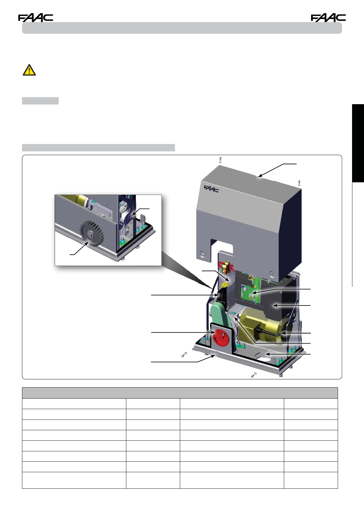
2 DESCRIPTION AND TECHNICAL SPECIFICATIONS ........................................................................................ 5
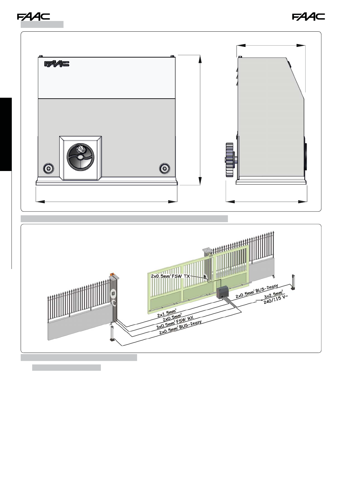
3 DIMENSIONS ....................................................................................................................................................... 6
4 ELECTRICAL PREPARATIONS (standard system with right-hand opening) ................................................ 6
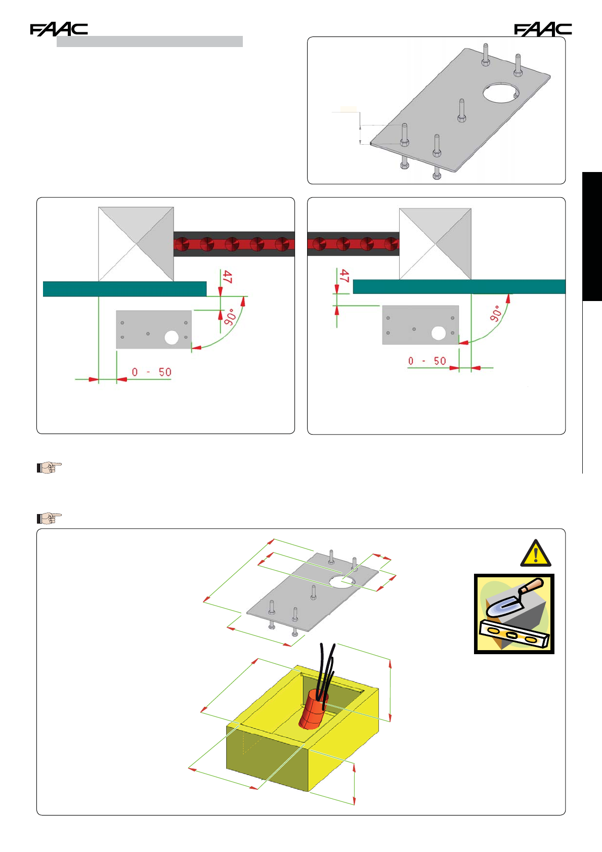
5 INSTALLING THE AUTOMATED SYSTEM ........................................................................................................ 6
5.1 PRELIMINARY CHECKS........................................................................................................................................6
5.2 WALLING IN THE FOUNDATION PLATE ............................................................................................................7
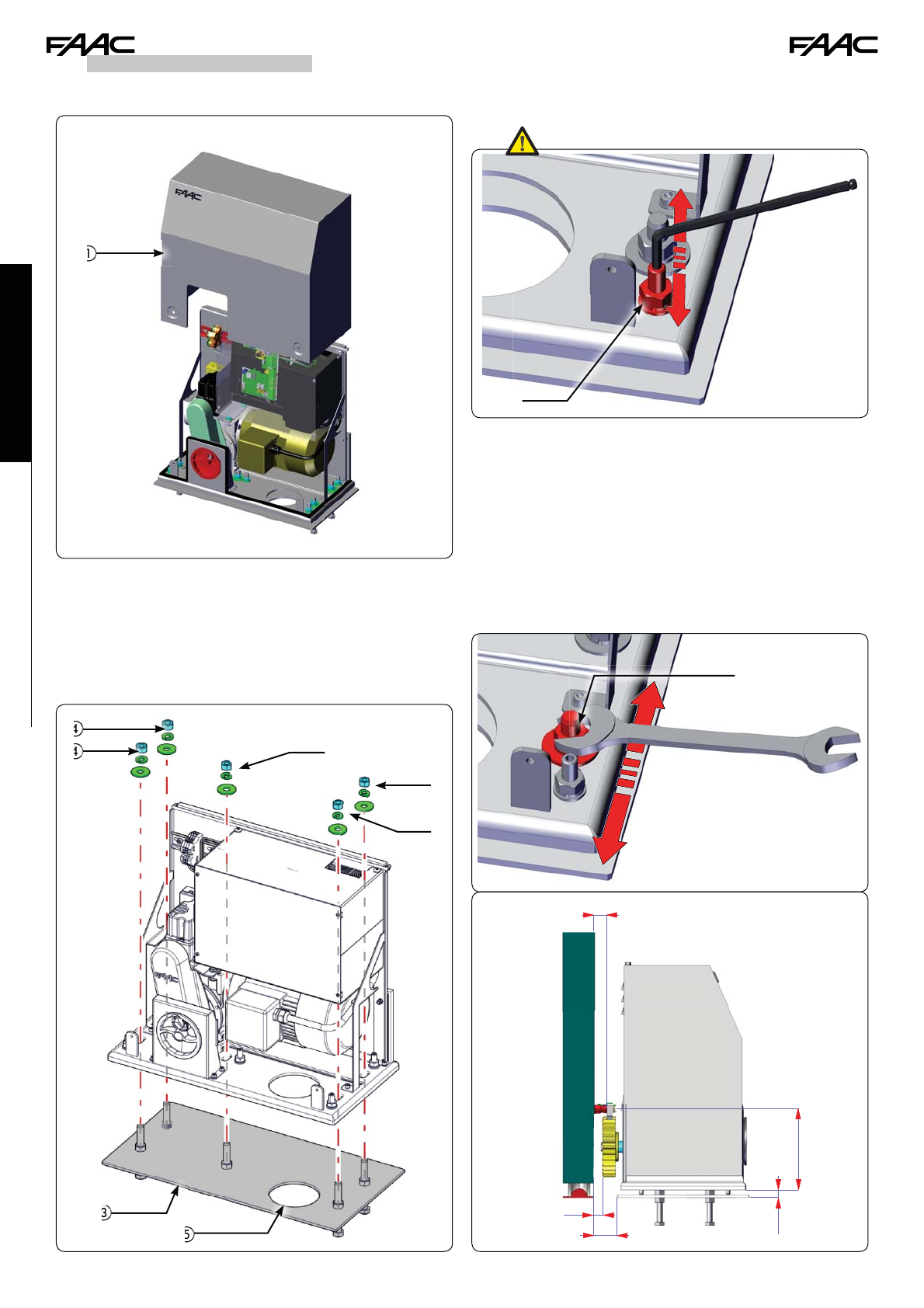
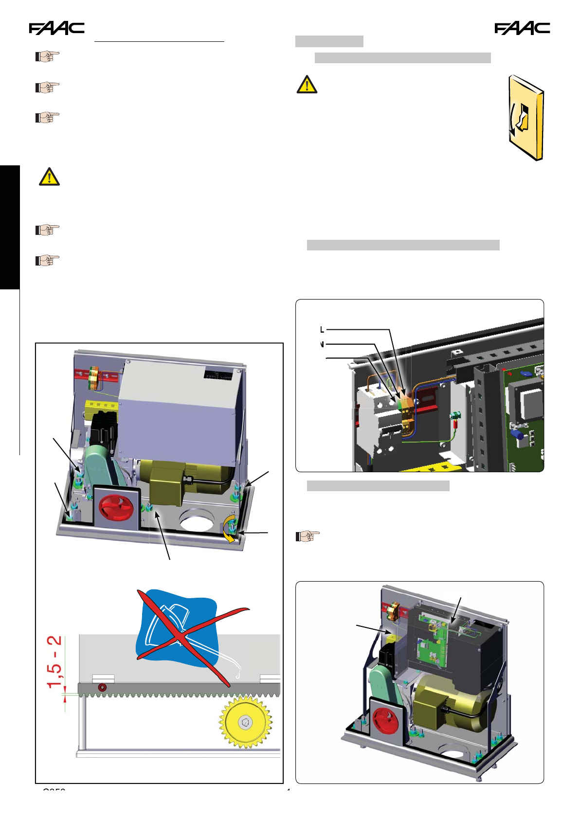
5.3 MECHANICAL INSTALLATION ............................................................................................................................8
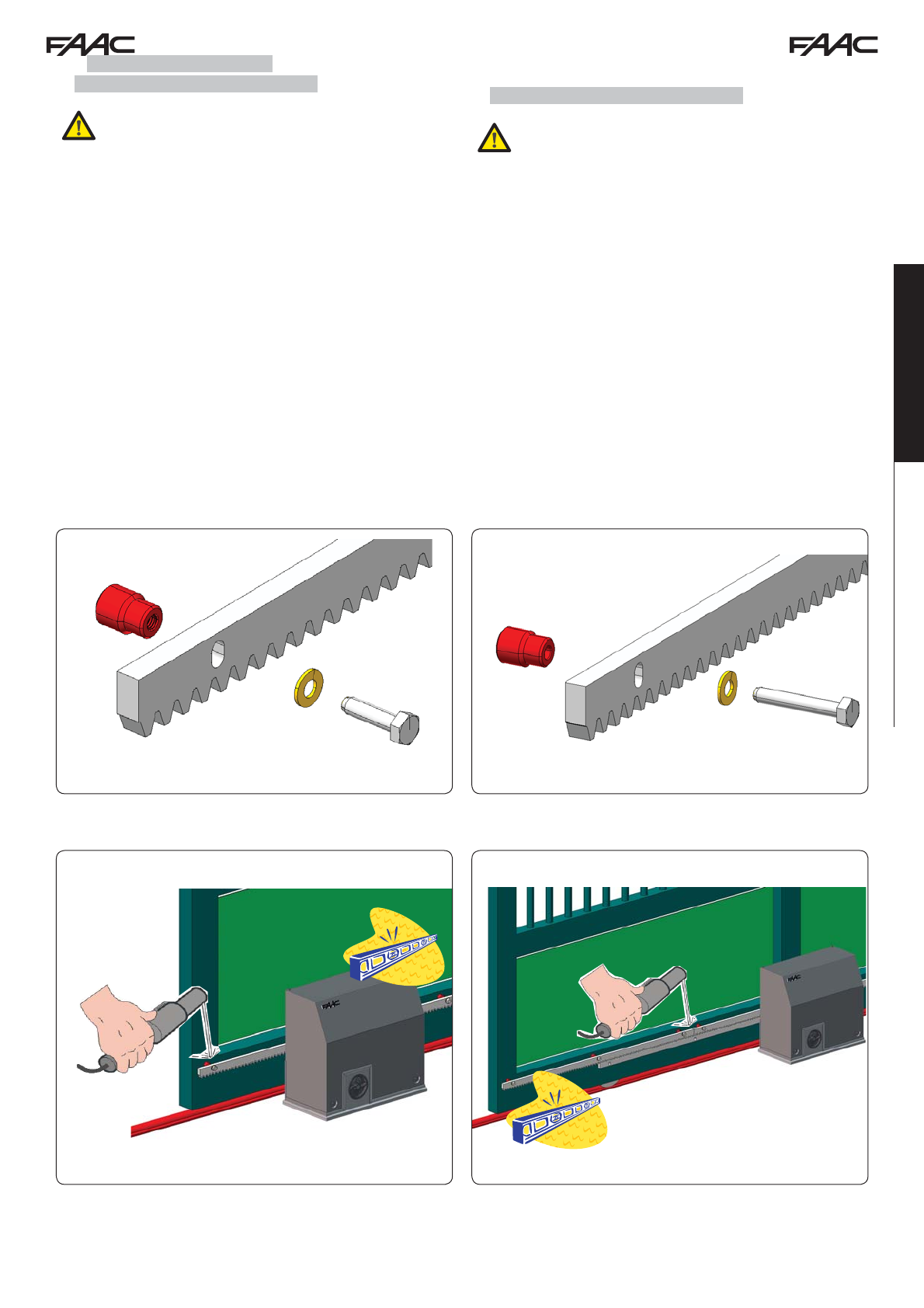
5.4 INSTALLING THE RACK .......................................................................................................................................9
5.4.1 WELD-ON STEEL RACK (Fig. 13)..............................................................................................................................9
5.4.2 SCREW-ON STEEL RACK (Fig. 14) ...........................................................................................................................9
6 OPERATION ...................................................................................................................................................... 10
6.1 CONNECTING THE CONTROL BOARD.............................................................................................................10
6.1.1 CONNECTIONS MADE BY THE INSTALLER...........................................................................................................10
6.1.2 ELECTRONIC CONTROL UNIT ...............................................................................................................................10
6.2 FINAL ADJUSTMENT OF THE LIMIT SWITCHES ............................................................................................11
7 TESTING THE AUTOMATED SYSTEM ............................................................................................................ 13
8 RELEASING/LOCKING THE OPERATOR ....................................................................................................... 13
9 MAINTENANCE ................................................................................................................................................ 13
10 REPAIRS ......................................................................................................................................................... 13
11 E850 ELECTRONIC CONTROL UNIT ............................................................................................................. 14
11.1 WARNINGS ........................................................................................................................................................14
11.2 E850 TECHNICAL SPECIFICATIONS ..............................................................................................................14
11.3 E850 LAYOUT AND COMPONENT DESCRIPTION..........................................................................................14
11.3.1 E850 LAYOUT .........................................................................................................................................................14
11.3.2 E850 COMPONENT DESCRIPTION........................................................................................................................14
11.4 ELECTRICAL CONNECTIONS..........................................................................................................................15
11.4.1 TERMINAL BOARD J1 - ACCESSORIES (FIG. 28)................................................................................................15
11.4.2 PHOTOCELL CONNECTION TO RELAYS AND SAFETY DEVICES WITH “N.C.” CONTACT.............................16
11.4.3 BUS PHOTOCELL CONNECTION ..........................................................................................................................16
11.4.4 TERMINAL BOARD J2, FLASHING LAMP (FIG.28)...............................................................................................17
11.4.5 TERMINAL BOARD J9 - POWER SUPPLY (FIG. 34).............................................................................................17
11.4.6
Connectors J3, J5 - rapid connection opening and closing limit switches ............................................................................................................17
11.4.7 FREQUENCY SELECTOR DS1 (FIG. 27) ...............................................................................................................17
11.4.8 CONNECTOR J4 - MINIDEC, DECODER AND RP CONNECTOR.........................................................................17
11.4.9 REVERSING GATE OPENING CONNECTIONS FROM RIGHT TO LEFT .............................................................17
11.5 PROGRAMMING ...............................................................................................................................................20
11.5.1 BASIC PROGRAMMING LEVEL.............................................................................................................................20
11.5.2 CHANGING THE PRE-SETTINGS...........................................................................................................................21
11.5.3 NEW BUS E850 SIGNAL.........................................................................................................................................21
11.5.4 ADVANCED PROGRAMMING LEVEL ....................................................................................................................22
11.5.5 SETTING THE INTEGRATED LOOP DETECTOR ..................................................................................................23
11.8 EXPERT PROGRAMMING LEVEL ...................................................................................................................24
11.6 E850 BOARD START-UP ...................................................................................................................................24
11.6.1 VERIFYING THE BOARD LEDs..............................................................................................................................24
11.6.2 VERIFYING THE BUS STATUS...............................................................................................................................24
11.7 TESTING THE AUTOMATED SYSTEM..............................................................................................................24
11.8.1. PERSONALISING THE OPERATING LOGIC.........................................................................................................25
1 11.9 OPERATING LOGICS TABLES .....................................................................................................................26
12 OMRON INVERTER CONTROL UNIT............................................................................................................. 28
12.1 DESCRIPTION OF THE INVERTER CONTROL PANEL .................................................................................28
12.2 PROGRAMMING THE INVERTER ...................................................................................................................30
12.3 12.3 INVERTER DEFAULTS .............................................................................................................................31
12.4 INVERTER ERROR............................................................................................................................................33
12.5 OPTIONAL ACCESSORIES...............................................................................................................................34
12.5.1 EXTERNAL PROGRAMMING KEYBOARD.............................................................................................................34

C850 5 532015 - Rev.B
Translation of the original instructions
ENGLISH
C850
We thank you for choosing this product. We are certain that it will fully meet your needs as to the performance it has been designed for.
This product has been designed and built for vehicle access control. AVOID ANY DIFFERENT USE.
Carefully read this manual supplied with the product as it contains important instructions regarding safety,
installation, use and maintenance.
1 GENERAL
These instructions apply to the following models: C850
The C850 is an electromechanical operator designed for moving sliding gates.
The non-reversing system is guaranteed by an electric brake that prevents manual movement of the sliding leaf when the motor is
stopped, and therefore does not require an electric lock.
A handy manual release makes it possible to manoeuvre the gate in case of black-out or operator inefficiency.
C850 TECHNICAL SPECIFICATIONS
Power supply (+6% / -10%) 230 V~ 50 Hz Limit switch type Mechanical
Max absorbed power (W) 1800 Motor control Inverter
Thrust on pinion (N) 1800 Usage temperature (°C) -20 +55
Max torque (Nm) 110 Gearmotor weight (kg) 49
Pinion type Z28 module 4 Protection class IP54
Recommended max gate length (m)
20 Gearmotor dimensions See Fig.02
Max leaf weight (kg) 1800 Frequency of use INDUSTRIAL
Gate speed (m/min) min 20
max 42 R.O.T. CD continuous duty
2 DESCRIPTION AND TECHNICAL SPECIFICATIONS
Fig. 1
1. Cover housing
2. Motor
3. Gearmotor
4. Cover for electronic gearmotor
5. Gearmotor release knob
6. Inverter
7. Foundation plate (not supplied)
8. Cable routing hole
9. Pinion
10. Control board
11. Limit switch
12. Electric brake

C850 6 532015 - Rev.B
295 mm
256 mm
510 mm
467 mm
ENGLISH
Translation of the original instructions
3 DIMENSIONS
5 INSTALLING THE AUTOMATED SYSTEM
5.1 PRELIMINARY CHECKS
For the safety and correct operation of the automated system, ensure that the following conditions are met:
• The gate structure must be designed to be automated. In particular, the diameter of the wheels must conform to the weight of
the gate being automated, there must be a guide on top and mechanical limit switches sized to suit the weight and speed of the
movable leaf, to avoid derailment of the gate;
• Initially, leave at least 10 cm of clearance between the movable leaf stopping points (FCO and FCC) and the
mechanical stops of the gate. The final adjustment is made once the inverter programming procedure is completed.
Minimum distance 3 cm.
• The gate sliding rail must be linear and horizontal.
• Manual movement of the gate must be smooth along the entire stroke.
• The characteristics of the ground must guarantee sufficient solidity of the foundation plinth.
• No tubes or electrical cables should be present in the plinth digging area.
• If the gearmotor is exposed to vehicle transit, provide for adequate protection against accidental impact, when possible.
• Ensure that there is an efficient earth plate for connecting the gearmotor.
Should the various elements not meet the above-mentioned conditions, adjust them so they do.
4 ELECTRICAL PREPARATIONS (standard system with right-hand opening)
Fig. 2
Fig. 3
Dimensions in mm
1. Operator
2. Flashing lamp
3. BUS 2easy photocells
4. Traditional photocells
5. Key control

C850 7 532015 - Rev.B
50 mm
Abb. 6
300
530
1500
120
270
Ø100
80,5
550
140
Abb
. 6
Translation of the original instructions
ENGLISH
5.2 WALLING IN THE FOUNDATION PLATE
1. Assemble the foundation plate as shown in Fig. 4.
2. The foundation plate must be positioned as shown in Fig. 5 (right-
hand closing) or Fig. 6 (left-hand closing) to guarantee the
correct meshing between the pinion and the rack.
3. Set the foundation plinth as shown in Fig. 7 and wall in the foundation plate using one or more sheaths for running the electrical cables
through the hole in the foundation plate.
Use a level to ensure that the plate is perfectly horizontal.
4. Wait for the cement to set.
5. Prepare the electrical cables for connecting the accessories and the electrical power, as shown in Fig. 3.
To facilitate connection to the control unit, pull out a stretch of cable measuring at least 1.5 m from the hole on
the plate.
Fig. 4
Fig. 7
Fig. 6Fig. 5
Dimensions in mm
Positioning the rack plate
ZINC-PLATED STEEL
right-hand closing
Positioning the rack plate
ZINC-PLATED STEEL
left-hand closing
Dimensions in mm
Dimensions
in mm
Dimensions
in mm

C850 8 532015 - Rev.B
25
19 47
160
10
ENGLISH
Translation of the original instructions
5.3 MECHANICAL INSTALLATION
1. Lift the cover to remove it (Fig. 8 ref. ).
2. Position the operator on the foundation plate and secure it without
tightening the nuts, Grover screws and washers supplied with
the foundation plate (not provided) (Fig. 9 ref. ). When
doing this, run the cables through the provided opening (Fig.
9 ref. ).
3. Use the adjustment screws to set the height of the gearmotor (Fig.
10 ref. ), referring to the measurements in Fig. 12.
4. Use a level to ensure that the gearmotor is perfectly horizontal.
5. Move the gearmotor horizontally to adjust the distance from the
rack (Fig. 11), referring to the measurements
in Fig. 12.
These operations are necessary to correctly
secure the rack and to make possible future
adjustments.
6. Once the adjustment is completed, tighten the nuts temporarily
(Fig. 9 ref. and Fig. 10 ref. ):
7. Prepare the gearmotor for manual operation, as described in
paragraph 8.
Fig. 8
Fig. 9
Fig. 10
Fig. 11
Fig. 12

C850 9 532015 - Rev.B
Translation of the original instructions
ENGLISH
5.4 INSTALLING THE RACK
5.4.1 WELD-ON STEEL RACK (Fig. 13)
Beforeinstallingtherack,releasethegearmotor,
as described in paragraph 8.
1. Install the three threaded pawls on the rack element,
positioning them on top of the slot. In this way the play on the
slot will make it possible to make future adjustments.
2. Manually set the leaf in closing position.
3. Evenly rest the first section of the rack on the pinion and weld the
threaded pawl to the gate, as shown in Fig. 15.
4. Manually move the gate, ensuring that the rack is NOT resting on
the pinion (leave 1.5 mm of clearance) and weld the second
and third pawls.
5. Draw up another rack element to the previous one using a piece
of rack to mesh the teeth of the two elements, as shown in
Fig. 16.
6. Manually move the gate and weld the three threaded pawls, con-
tinuing until the gate is completely covered.
5.4.2 SCREW-ON STEEL RACK (Fig. 14)
Beforeinstallingtherack,releasethegearmotor,
as described in paragraph 8.
1. Manually set the leaf in closing position.
2. Rest the first piece of rack level on the pinion and place the spacer
between the rack and the gate, positioning it on top of the
slot. In this way the play on the slot will make it possible to
make future adjustments.
3. Mark the drilling point on the gate. Drill 6.5 mm Ø hole and thread
using an 8 mm Ø male. Tighten the bolt.
4. Manually move the gate, ensuring that the rack is NOT resting
on the pinion (leave 1.5 mm of clearance) and repeat the
operations from point 3.
5. Draw up another rack element to the previous one using a piece
of rack to mesh the teeth of the two elements, as shown in
Fig. 16.
6. Manually move the gate and, as for the first element, proceed with
securing until the gate is completely covered.
Fig. 13 Fig. 14
Fig. 15 Fig. 16

C850 10 532015 - Rev.B
C
C8
C8
50
50
1
1
OFF
L
N
L
L
L
L
L
L
L
L
L
L
L
L
N
PE
ENGLISH
Translation of the original instructions
Important notes for installing the rack:
Check that during gate travel, all the rack
elements remain on the pinion.
Do not weld the rack elements together or to the
spacers.
Once rack installation is complete, to guarantee
correct meshing with the pinion, lower the
gearmotor approximately 1.5 - 2 mm using the
provided adjustment screws (Fig. 17 ref. ).
Tighten the fixing nuts (Fig. 9 ref. ) with 80
Nm of torque.
Tighten the fixing nuts (Fig. 10 ref. ) with 40
Nm of torque.
Do not use grease or other lubricating products
between the pinion and the rack (Fig. 17)
Manually check that the gate reaches the
mechanical stops smoothly and that there is
not friction during its travel.
6 OPERATION
6.1 CONNECTING THE CONTROL BOARD
Before carrying out any work on the board
(connections, programming, maintenance)
always cut off the electrical power.
• Follow points 10, 11, 12, 13 and 14 of the GENERAL
SAFETY REGULATIONS.
• Following the instructions shown in Fig. 3, place the
cables in the runners and make the electrical connections
with the chosen accessories.
• Always separate the power cables from the control and safety
cables (button, receiver, photocells, etc.).
• To avoid possible electrical disturbance, use separate
sheathing.
6.1.1 CONNECTIONS MADE BY THE INSTALLER
Connect the 230 VAC line (see fig. 18):
• L: Phase
• N: Neutral
• PE: Earth
6.1.2 ELECTRONIC CONTROL UNIT
Inside the operator, the electronic control unit is secured to a
bracket (Fig. 19 ref. ) and protected by a cover (Fig. 19 ref. ).
To correctly connect and program the control
unit, removethe coverand followthe instructions
in section 11 (E850 Electronic Control Unit).
Fig. 17
Fig. 18
Fig. 19
Dimensions in mm

C850 11 532015 - Rev.B
Translation of the original instructions
ENGLISH
6.2 FINAL ADJUSTMENT OF THE LIMIT SWITCHES
To correctly adjust the limit switches, the control unit must be installed and correctly connected with all the
control and safety accessories.
The stopping and deceleration of the gate, during opening and/or closing, occurs when the cams inside the device activate the mi-
croswitches corresponding to the assigned function.
FCO = opening limit switch (screw 3)
FCC = closing limit switch (screw 2)
ROP = start of opening deceleration (screw 4)
RCL = start of closing deceleration (screw 1)
1. Prepare the operator for MANUAL operation, as described in section 8.
2. Loosen the screws and remove the limit switch unit cover (Fig. 20 ref. ).
3. Set the sliding leaf in open position, at least 10 cm before the mechanical limit stop.
4. Loosen the central locking screw of the limit switch unit (Fig. 22 ref. ).
5. Turn the screw corresponding to the FCO opening limit switch (Fig. 21 ref. ) until the microswitch is engaged by the cam.
6. In chart 1, knowing the weight of the sliding leaf, choose the operating speed and calculate the corresponding MINIMUM STOP
SPACE S[mm].
7. Then, move the sliding leaf back in closing position according to the amount of identified STOP SPACE.
8. Turn the screw corresponding to ROP opening deceleration (Fig. 21 ref. ) until the microswitch is engaged by the cam.
9. Place the sliding leaf in closed position, at least 10 cm before the mechanical limit stop.
10. Turn the screw corresponding to the FCC closing limit switch (Fig. 21 ref. ) until the microswitch is engaged by the cam.
11. Move the sliding leaf back in opening position according to the amount of STOP SPACE identified in chart 1.
12. Turn the screw corresponding to RCL closing deceleration (Fig. 21 ref. ) until the microswitch is engaged by the cam.
13. In chart 2, knowing the weight and the operating speed of the sliding leaf, calculate the corresponding DECELERATION TIME t[s].
ROP - RCL MINIMUM STOP SPACE
DECELERATION TIME
Chart 1
Chart 2
Example:
P = 1000 kg
V = 0.6 m/sec
S = 400 mm
Example:
P = 1000 Kg
V = 0.6 m/sec
t = 1.7 sec

C850 12 532015 - Rev.B
FCC
F
F
RCL
RCL
ROP
FCO
FCC
FCO
ROP
ENGLISH
Translation of the original instructions
14. Set the F003 DECELERATION TIME and A021 OPERATING SPEED in the inverter (see section 12.2)
15. Do not modify the deceleration points (ROP/RCL) and/or stops (FCO/FCC) before having set the deceleration time and speed of the
inverter (see section 12.2)
16. Tighten the central locking screw of the limit switch unit (Fig. 22 ref. ).
17. Manually place the sliding leaf at half its travel and ensure that the limit switch position corresponds to Fig. 21
18. Refit the limit switch cover.
19. Manually close the sliding leaf.
20. Prepare the operator for NORMAL operation, as described in section 8.
21. Ensure that there is no danger and the safety devices are operating correctly.
22. Give an OPEN pulse and verify correct operation.
The maximum adjustable STOP SPACE is 5 m.
The operator is supplied with factory settings for automating gates with RIGHT-HAND opening. If the gate
requires LEFT-HAND opening, the association of the related opening and closing limit switches is reversed. For
these operations, follow the instructions contained in paragraph 11.4.9 Reversing Gate Opening Connections
from Right to Left.
FCO = opening limit switch (screw )
FCC = closing limit switch (screw )
ROP = start of opening deceleration (screw )
RCL = start of closing deceleration (screw )
Fig. 20
Fig. 21 Fig. 22

C850 13 532015 - Rev.B
Translation of the original instructions
ENGLISH
9 MAINTENANCE
We recommend checking system operation every six months,
with special attention to the safety devices (including the motor
thrust power, which must comply with the regulations in force)
and release devices.
10 REPAIRS
For repairs, contact an authorised FAAC Service Centre.
7 TESTING THE AUTOMATED SYSTEM
Once operator installation has been completed, carefully check
operation of all the connected accessories and safety devices.
Refit the transparent guard covering the control unit.
Fit the housing (Fig. 23 ref. ) and secure it using the four provided
screws (Fig. 23 ref. ).
Give the customer the “User’s Manual” and show how to correctly
operate and use the gearmotor, pointing out the areas of potential
danger of the automated system.
8 RELEASING/LOCKING THE OPERATOR
To manually move the gate, we recommend
cutting off electrical power. Rotating the knob
prevents any motor movement.
To release the gearmotor, proceed as follows:
1. Insert the provided key and turn clockwise (Fig. 24 ref. ).
2. Turn the release system clockwise until it reaches the mechanical
stop (Fig. 24 ref. ).
3. Open or close the gate manually.
Fig. 23
Fig. 24
To lock the gearmotor, proceed as follows:
1. Turn thereleasesystem anti-clockwiseuntil itstops (Fig.25ref. ).
2. Turn the key anti-clockwise and then remove it from the lock (Fig.
25 ref. ).
Turning the release system knob clockwise will
prevent any movement of the motor.
Operator releasing and locking operations can
be carried out in any gate position.
Fig. 25

C850 14 532015 - Rev.B
ENGLISH
Translation of the original instructions
11 E850 ELECTRONIC CONTROL UNIT
11.1 WARNINGS
Important: Before carrying out any work on the control unit (connections, maintenance) always cut off the
electrical power.
• Always install a differential magnetothermic switch with a suitable activation threshold upstream from the system.
• Connect the earthing cable to the corresponding terminal on connector J9 of the equipment (see fig.28).
• Always separate the power cables from the control and safety cables (button, receiver, photocells, etc.). To avoid any electrical
disturbance, use separate sheaths or a shielded cable (with the shield connected to the earth).
11.2 E850 TECHNICAL SPECIFICATIONS
Power voltage
230 V
~
(+6% -10%) - 50/60 Hz
Absorbed power 7 W
Maximum motor
load 1800 W
Accessories
power supply 24 Vdc
Max accessories
current 500 mA
Operating ambient
temperature from -20°C to +55°C
Protection F1 = F 5A - 250V F2 = T 0,8A - 250V
or
F1 = F 10A - 120V F2 = T 0,8A - 120V
Operating time Programmable (from 0 to 4 min)
Pause time Programmable (from 0 to 4 min)
Programming 3 programming levels for greater
flexibility of use
Rapid connector 5-pin board connector for Minidec,
Decoder, RP/RP2 Receiver
Characteristics Multi-function display, BUS technology and
INTEGRATED METAL MASS DETECTOR
11.3 E850 LAYOUT AND COMPONENT DESCRIPTION
11.3.1 E850 LAYOUT
11.3.2 E850 COMPONENT DESCRIPTION
DL SIGNALLING AND PROGRAMMING DISPLAY
LED INPUT STATUS CONTROL LEDs
J1 LOW-VOLTAGE TERMINAL BOARD
J2 MOTOR, FLASHING LAMP AND FAN CONNECTION
TERMINAL BOARD
J3 ROP OPENING DECELERATION CONNECTOR
J4 DECODER / MINIDEC / RP RECEIVER CONNECTOR
J5 RCL CLOSING DECELERATION CONNECTOR
J6 STOP CONNECTOR
J9 230 VAC POWER SUPPLY TERMINAL BOARD
DS1 LOOP 1 and LOOP 2 FREQUENCY SELECTOR
F1 MOTOR FUSES AND TRANSFORMER PRIMARY (F 5A)
F2 LOW-VOLTAGE AND ACCESSORIES FUSE (T 800mA)
F“F” PROGRAMMING BUTTON
+“+” PROGRAMMING BUTTON
-“-” PROGRAMMING BUTTON
TF1 TRANSFORMER
Fig. 26
Fig. 27

C850 15 532015 - Rev.B
Translation of the original instructions
ENGLISH
FSW OP
FSW CL
RCL
FCCFCO
FSW CL
EF
ROP
INVERTER
L
LIMIT SWITCH UNIT
To connect the
photocells and
safety devices,
refer to paragraph
11.4.2.
Fig. 28
11.4.1 TERMINAL BOARD J1 - ACCESSORIES (FIG. 28)
J6=FCC - FCO - Manoeuvre stop command.
J5=RCL - Start of closing deceleration.
J3=ROP - Start of opening deceleration.
LOOP 1 - LOOP 1 magnetic loop (OPEN - terminals 1-2): for OPENING.
LOOP 2 - LOOP 2 magnetic loop (SAFETY/CLOSE - terminals 3-4): for SAFETY/CLOSING.
EF - Electrical stopping brake for motor locking.
OPEN - “Open” command (N.O. - terminal 5): means any pulse generator (e.g.: button) which, by closing a contact, commands
opening and/or closing of the gate.
CLOSE - “Close” command (N.O. - terminal 6): means any pulse generator (e.g.: button) which, by closing a contact, commands
closing of the gate.
FSW CL - Safety contact when closing (N.C. - terminal 7): he purpose of the closing safety devices when closing is to protect the
area affected by the movement of the gate during the closing phase, reversing the motion. They never trip during the opening cycle.
The CLOSING SAFETY DEVICES, if tripped when the automated system is open, will prevent the closing movement.
If CLOSING safety devices are not connected, jumper terminals FSW CL and GND (Fig. 32).
NOTE: If this connection is made, it will not be possible to use the FAILSAFE control.
STOP - STOP contact (N.C. - terminal 8): means any device (e.g.: button) which, by opening a contact, can stop movement of the
automated system.
If STOP devices are not connected, jumper terminals STOP and GND (Fig. 32).
FSW OP - Safety contact when closing (N.C. - terminal 9): the purpose of the opening safety devices when opening is to protect
the area affected by the movement of the gate during the opening phase, reversing its motion. They never trip during the closing cycle.
The OPENING SAFETY DEVICES, if tripped when the automated system is closed, will prevent the opening movement.
If OPENING safety devices are not connected, jumper terminals FSW OP and GND (Fig. 32).
GND (terminals 10-11-19) - Accessories power supply negative
24 VDC (terminals 12-13) - Accessories power supply positive
The max. load of the accessories is 500 mA. To calculate absorption, refer to the instructions included with the
individual accessories.
OUT 1 - DECELERATION COMMAND (terminal 14): signal telling the inverter that deceleration has begun.
OUT 2 - CLOSE COMMAND (terminal 15): signal telling the inverter that the gate is closing.
OUT 3 - OPEN COMMAND (terminal 16): signal telling the inverter that the gate is opening.
To avoid compromising correct system operation, do not exceed the power indicated in fig. 28.
OUT 4 - Output 4 open-collector +24 VDC (terminal 18): the output can be set in one of the functions described in Advanced Pro-
gramming Level (par. 11.5.2.). The default value for ALL PRE-SETTINGS is BUS COMMUNICATION.
Maximum load: 24 VDC with 100 mA.
60 W max
230 V~ 230 V~
50/60 Hz
11.4 ELECTRICAL CONNECTIONS

C850 16 532015 - Rev.B
J1
FSW OP
FSW CL
J1
+24
GND
+24
GND
SAFE
TX
RX
1
2
5
4
3
1
2
FSW OP
FSW CL
J1
+24
GND
+24
GND
SAFE
TX
RX
1
2
5
4
3
1
2
TX
RX
1
2
5
4
3
1
2
+24
GND
+24
GND
FSW OP
FSW CL
DS1
DL1
DL2
BUS BUS
RX - TX
DL2
DS1
ONON
BUS BUS
DS1
DL1
DL2
BUS BUS
DL2
DS1
ONON
BUS BUS
2EASY
18
19
DS1
DL1
DL2
BUS BUS
RX - TX
DL2
DS1
ONON
BUS BUS
2EASY
18
19
ENGLISH
Translation of the original instructions
11.4.2 PHOTOCELL CONNECTION TO RELAYS AND SAFETY DEVICES WITH “N.C.” CONTACT
The E850 board is designed to connect to closing safety devices that trip only during gate closing movement, and are therefore
suitable for protecting the gate closing area form risk of impact.
If the connection of two or more safety devices is required (N.C. contacts), they must be placed in series, as
shown in figures 29, 30, and 31 under the wording “SAFE”.
Fig. 30
Fig. 29
Connection without safety devices
Fig. 31
Fig. 33
11.4.3 BUS PHOTOCELL CONNECTION
BUS-technology photocells are connected to the E850 control unit ALL IN PARALLEL, as shown in Fig. 32 and Fig. 33 using a single
power supply/communication line.
BUS photocells and pulse generators do not require a matching polarity connection.
The board is designed to connect up to 8 pairs of BUS 2easy photocells.
The photocells are divided by quantity in the following groups:
Pairs of CLOSING photocells: max 7
Pairs of photocells for OPEN pulse: max 1
Fig. 32
Connecting 1 pair of CLOSING photocells Connecting 2 pairs of CLOSING photocells
2nd Pair of Photocells
1st Pair of Photocells

C850 17 532015 - Rev.B
RP / RP2
E850E850
J4
Translation of the original instructions
ENGLISH
After positioning the BUS-technology photocells, proceed with
selecting the address for each pair using various combinations of
the DIP-SWITCHES located on each photocell.
Set the SAME chosen DIP-SWITCH ADDRESS on both
the transmitter and receiver of the same pair.
Ensure that two or more pairs of photocells do not
have the same address.
If no BUS accessories are used, leave terminals 18 and
19 free.
The following table describes how to set the dip-switches located
inside the transmitter and receiver of the BUS photocells.
Table - Addressing BUS photocell PAIRS
To allow operation of the installed BUS acces-
sories, store them on the board, as described
in paragraph 11.5.3.
11.4.4 TERMINAL BOARD J2, FLASHING LAMP (FIG.28)
LAMP (LAMP-COM): Flashing lamp output.
11.4.5 TERMINAL BOARD J9 - POWER SUPPLY (FIG. 34)
PE: Earth connection
N: 230 V~ or 115 V~ Power supply (Neutral)
L: 230 V~ or 115 V~ Power supply (Line)
For correct operation, you must connect the
board to the system’s earth conductor. Ensu-
re that a suitable differential magnetothermic
switch has been installed upstream.
11.4.6
ConnectorsJ3,J5-rapidconnectionopeningandclosinglimitswitches
(FIG.28)
Rapid connector for connecting the opening (J3) and closing (J5)
limit switches.
11.4.7 FREQUENCY SELECTOR DS1 (FIG. 27)
DIP-SWITCH used to set the HIGH or LOW work frequency of the
vehicle detection loops. See section 11.5.5.
11.4.8CONNECTORJ4-MINIDEC,DECODERANDRPCONNECTOR
Used for the rapid connection of the Minidec, Decoder and RP /
RP2 Receivers.
If a 2-channel receiver is used, like the RP2, it will be possible to
directly command automated system OPEN and CLOSE from a
2-channel radio control.
If a 1-channel receiver is used, like the RP, it will only be possible
to command OPEN.
Connect the accessory with the components side facing inside
the board.
Boards should be connected or disconnected
ONLY after having cut off electrical power.
11.4.9 REVERSING GATE OPENING CONNECTIONS FROM
Fig. 35
Example of radio accessory connection
Fig. 34
Dip1 Dip2 Dip3 Dip4 Ref. Type
ON OFF OFF OFF
B-C OPENING
OFF OFF OFF ON
OFF OFF ON OFF
OFF OFF ON ON
OFF ON ON OFF
OFF ON ON ON
ON OFF OFF OFF
DCLOSING
OFF OFF OFF ON
ON OFF ON OFF
ON OFF ON ON
ON ON OFF OFF
ON ON OFF ON
ON ON ON OFF
OFF ON OFF OFF AOPENING and
CLOSING
OFF ON OFF ON
ON ON ON ON / OPEN
PULSE
TX
DIP-SWITCH
RX
DIP-SWITCH
SAME
ADDRESS

C850 18 532015 - Rev.B
ENGLISH
Translation of the original instructions
RIGHT TO LEFT
Connections to the E850 board are factory set for gates designed to open toward the RIGHT. If at installation the
gate requires LEFT-HAND opening, the connections will be inverted on site, as shown in figures 36 and 37.
Fig. 36
GATE WITH RIGHT-HAND OPENING (DEFAULT) GATE WITH LEFT-HAND OPENING
21
OMRON INVERTER
17
15
E850
2TUO
3TUO
GREENGREEN
BROWN
BROWN
BROWN
J5J6 J3
ROP
RCL
FCC-FCO
WHITE
YELLOW
GREEN
PINK
GREY
21
OMRON INVERTER
17
15
E850
2TUO
3TUO
J5J6 J3
GREEN
GREEN
RCL
ROP
FCC-FCO
WHITE
YELLOW
GREEN
BROWN
BROWN
BROWN
PINK
GREY

C850 19 532015 - Rev.B
Translation of the original instructions
ENGLISH
Fig. 37
RIGHT-HAND OPENING (DEFAULT)
LEFT-HAND OPENING

C850 20 532015 - Rev.B
ENGLISH
Translation of the original instructions
11.5 PROGRAMMING
To program automated system operation, you must access “PROGRAMMING”
mode.
Programming is divided into three levels: BASIC,ADVANCED and EXPERT.
Changes to the programming parameters become
immediately effective, while final storage occurs
only upon exiting programming and returning to the
automated system status display. If the equipment
is powered down before returning to the automated
system status display, all changes made will be lost.
It is possibleto returnto the statusdisplay at anypoint
during programming at any level by simultaneously
pressing “F” and “-”
11.5.1 BASIC PROGRAMMING LEVEL
BASIC PROGRAMMING LEVEL is accessed by pressing F:
• when pressed (and held) the name of the first function is displayed.
• releasing the key, the function value is displayed and can be modified
using the +and - keys.
• when Fis pressed again (and held) the name of the following function
is displayed, and so on.
• once the last function is reached, pressing Fwill exit programming
mode and the display will go back to showing the inputs status.
Display Funzione Default
L2
LOOP 2:
When this function is enabled, the loop
connected to the Loop2 input will serve as a
SAFETY / CLOSE function, i.e. it will operate
as a SAFETY during closing and, once it
is uncovered, it will command the board to
CLOSE.
Y= loop2 active
no = loop2 not active
Warning: if the function does not activate, the
state of Loop2 will in any case be available
on one of the duly set outputs (see advanced
programming level).
no
H1
BOOST LOOP 1 FUNCTION:
Y= Active no = Disabled
This function lets you increase the sensitivity
level at the time of detection. When the vehicle
moves away from the loop, the sensitivity will
return to the selected level. This system makes
it possible to maintain the detection contact
even in case of very tall vehicles or during the
transit of a tractor with trailer.
no
H2
FUNZIONE BOOST LOOP 2:
Y= Active no = Disabled
See BOOST LOOP1 function.
no
S1
LOOP 1 SENSITIVITY
Regulates the sensitivity of the loop
01 = minimum
10 = maximum
05
S2
LOOP 2 SENSITIVITY
Regulates the sensitivity of the loop
01 = minimum
10 = maximum
05
St
AUTOMATED SYSTEM STATUS:
Exit programming,
store settings and return to automated system
status display.
00 Closed
01 Pre-flashing during opening
02 Opening
03 Open
04 Paused
05 Pre-flashing during closing
06 Closing
07 Stopped ready to close
08 Stopped ready to open
09 Stopped with closing safety devices and then opens
10 Opening safety devices tripped, then opens
Display of the automated system status Stis ex-
tremely important for the installation/maintenance
technician in order to distinguish the logical pro-
cessesthatthe board carriesout during movement.
If, for example, the automated system status is
CLOSED, the display MUST read
00. When the
OPEN command is received, the display will chan-
ge to 01, if pre-flashing is enabled, or directly to
02 (the OPENING movement) to then display 03
once the OPEN gate position is reached.
PROGRAMMAZIONE LIVELLO BASE
Display Function Default
dF
PARAMETER LOADING:
00 Neutral condition
01 FAAC 1 Default loaded
LEAVE ON 00 IF YOU DO NOT WISH TO
CHANGE PROGRAMMING.
For a description of the parameter dF refer to
section 11.5.2.
00
bu
BUS ACCESSORIES MENU
no = BUS devices entering request
section 11.5.3.
no
LO
OPERATING LOGICS:
AAutomatic
A1 Automatic 1
EP Semi-Automatic step-by-step
ESemi-Automatic
PE Photocell automatic
CDead-man
CU Custom
E
PA
PAUSE TIME:
Is effective only if an automatic logic has been
selected. Adjustable from 0to 59 sec. in
one-second steps.
Next, visualisation changes to minutes and
tenths of a second (separated by a decimal
point) and time is adjusted in 10-second steps
up to the maximum value of 4.1 minutes.
e.g.: if the display shows 2.5, the pause time
corresponds to 2 min. and 50 sec.
20
L1
LOOP 1:
When this function is enabled, the loop
connected to the Loop 1 input will serve as an
OPEN function.
Y= loop1 active
no = loop1 not active
Warning: if the function does not activate, the
state of Loop1 will in any case be available
on one of the duly set outputs (see advanced
programming level).
no
Table of contents
Other FAAC Garage Door Opener manuals