27
ENGLISH
1
0
2
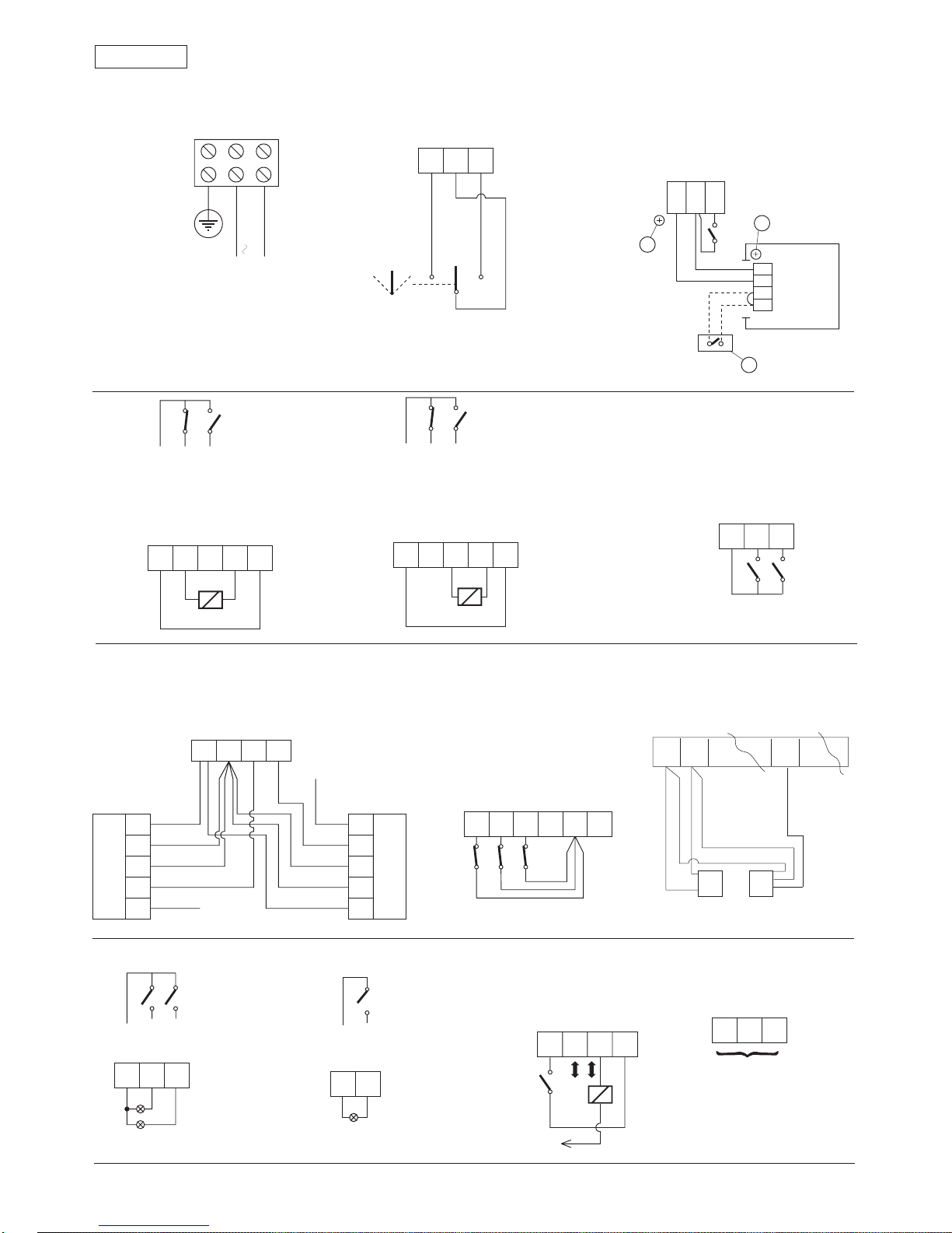
given to enable the mechanical release of the system.
7. Accessories power supply (+24 Vdc)
8. Accessories power supply (0 Vdc)
9. Internal command: any control device (pushbutton,
photocell, sensor, etc.) which, by closing a contact, can
command an opening cycle of the system from inside.
10. External command: any control device (pushbutton,
photocell, sensor, etc.) which, by closing a contact, can
command an opening cycle of the system from outside.
Fig. 17 shows the control device connection. To install
more than one internal/external control device, connect
the N.O. contacts in parallel.
Connecting microwave radar / passive infrared sensors.
In the conventional configurations the control units are
microwave radar and/or passive infrared sensors. To
connect the FAAC sensors/radar units equipped with a 5-
pole electrical cable, refer to fig. 18.
11. Emergencycontrol(fig.19/a):anycontroldevice(normally
a pushbutton) which, by opening a contact, commands
an emergency closure of the system. Alternatively this
input can be used to command emergency opening by
programming the system in a suitable manner using the
CODIS programming unit (optional).
To install more than one emergency control device,
connect the N.C. contacts in series.
N.B.: If emergency control devices are not connected,
jumper inputs 11 and 15.
Activating function no. 6 at CODIS programming level III
enablestheemergencycontroltobeactivatedbyclosing
a N.O. contact.
In this case, in order to install more than one emergency
control device, connect the N.O. contacts in parallel.
12. STOP safety control (fig. 19/a): any device (safety sensor,
photocell,etc.)which,byopeningacontact,hasasafety
effect on the operating cycle. In particular, this safety
device interrupts the opening/closing movement of the
door.
When the safety device is disengaged, the door resumes
its opening/closing movement and continues to the end
of the cycle.
To install more than one STOP safety device, connect the
N.C. contacts in series.
N.B.: If STOP safety devices are not installed, jumper inputs
12 and 15.
13. CLOSURE safety command (fig. 19/a): any device (safety
sensor, photocell, etc.) which, by opening a contact, has
a safety function on the closing movement of the door.
The safety device causes an immediate reversal of the
closing movement of the door, but has no effect on the
opening movement of the door.
To install more than one CLOSURE safety device, connect
the N.C. contacts in series.
N.B.:IfCLOSUREsafetydevicesarenotconnected,jumper
inputs 13 and 15.
Connection of MINISWITCH photocells
TheMINISWITCHphotocellscanbeusedasasafetydevice.
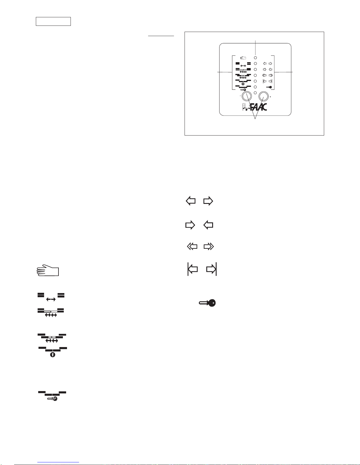
POSITION “1”: AUTOMATIC
When an internal/external command is given, the door opens and then re-closes after the pause time.
POSITION “0”: MANUAL/NIGHT
The position “0” can be used to select two different operating functions according to the programming carried out on the 961
B-E programming unit (see section 5.3.3).
The two functions are:
MANUAL: The door can be opened manually. The return spring pulls the door closed again.
NIGHT: The external command is inactive. The door can be opened solely by
activating the internal command (fig. 22) or EMERGENCY OPENING (fig. 19/a) input.
POSITION “2”: OPEN
When this function is selected, the door opens and remains open. The door can be closed only by activating the EMERGENCY
CLOSURE input (fig.19/a).
Fig. 24
For connection, see figure 19/b.
14. Accessories power supply (+24 Vdc)
15. - 16. Accessories power supply (0 Vdc)
17. Status signal output: Common (fig. 20)
18. Dooropen signaloutput (max.contactcapacity 0.5A/24
Vdc) (fig. 20)
19. Door closed signal output (max. contact capacity 0.5 A /
24 Vdc) (fig. 20).
Terminals 17/18 and 17/19 can be used to power two 24
Vdc(max.0.5A)warninglampstoprovidedooropenand
door closed signals respectively (fig. 20).
20. -21. Alarmsignal output (max.contactcapacity0.5A/24
Vdc).
Terminals 20 and 21 can be used to power a 24 Vdc (max.
0.5 A) warning lamp for remote signalling of an alarm
condition (fig. 21).
Theoperatorsignalsamalfunctionbymeansofanacoustic
alarm from a buzzer (see Table 6).
22. “KEY” opening command (fig. 22): any device which, by
closing a contact for more than 3 seconds, commands
door opening in any operating function selected.
To install more than one “KEY” command, connect the
N.O. contacts in parallel.
23. Output for “DOUBLE LEAF” application (fig. 22): seesection
9.2
24. Outputfor GONGacousticsignal/Output for“INTERLOCK”
application (fig. 22):
WhentheCLOSURE safety devicecomesintooperation,it
activates the output between terminals 14 and 24 for one
secondatintervalsof0.5seconds.Theoutputissuitablefor
controllinganacousticsignal(GONG).Themaximumload
is 300 mA (fig. 22).
In the event of “INTERLOCK” operation, it is necessary to
activatefunctionno.3atCODISlevelIIIanduseoutputs24
and 25 for the connection between the two operators
(see section 9.1).
25. 0 Vdc
26. -27.-28.PCconnection:Theseoutputsallowforinterfacing
with a PC, which if necessary can control a number of
doors from a single central unit (fig. 23).
Forthisapplicationrefertotherelevanttechnicalmanual.
dRESET button
N.B.: ToRESET,holddownthebutton foratleast 4seconds.
ePosition monitoring microswitch connector (fig. 1 - ref. 4).
fProgramming unit connector (2 pole)
gProgramming unit connector (14 pole)
7. FUNCTION SWITCH
The 961 B-E operator has a 3-position function switch (0-1-2)
mounted on one of the end covers (fig. 1 - ref. 12). This cover
can be fitted on the right or the left as required (fig. 8).
The switch electrical connection is shown in fig. 13.
The selectable operating functions are shown in fig. 24.