FAAC 593 User manual

593
593
ist
umweltfreundlich
100% Altpapier
pour la nature
papier recyclé 100%
for nature
recycled paper 100%
per la natura
carta riciclata 100%
para la naturaleza
100% papel reciclado
C
E
R
M
E
T
A
Z
I
E
N
D
A
C
E
R
T
I
F
I
C
A
T
A
UNI EN ISO 9001-085

9
ENGLISH
EC MACHINE DIRECTIVE COMPLIANCE DECLARATION
(DIRECTIVE 89/392 EEC,APPENDIX II, PART B)
Manufacturer: FAAC S.p.A.
Address: Via Benini, 1
40069 - Zola Predosa
BOLOGNA - ITALY
Hereby declares that: the 593 automation system
•isintendedtobeincorporatedintomachinery,ortobeassembledwithother
machinery to constitute machinery in compliance with the requirements of
Directive 89/392 EEC, and subsequent amendments 91/368 EEC, 93/44 EEC
and 93/68 EEC;
•complieswiththeessentialsafetyrequirementsinthefollowingEECDirectives:
73/23 EEC and subsequent amendment 93/68 EEC.
89/336 EEC and subsequent amendments 92/31 EEC and 93/68 EEC.
and furthermore declares that unit must not be put into service until the
machinery into which it is incorporated or of which it is a component has
been identified and declared to be in conformity with the provisions of
Directive89/392EECandsubsequentamendmentsenactedbythenational
implementing legislation.
Bologna, 1 January 1997
Managing
Director
A. Bassi

10
ENGLISH
IMPORTANT NOTICE FOR THE INSTALLER
GENERAL SAFETY REGULATIONS
1) WARNING! FAAC strongly recommends to follow these instructions literally for the safety of persons. Improper
installation or misuse of the product will cause very serious damages to persons.
2) Packaging material (plastic, polystyrene etc.) is a potential hazard and must be kept out of reach of children.
3) Read the instructions carefully before installing the product.
4) Keep these instructions for future reference.
5) Thisproduct has been designed and manufactured onlyfor the use stated in this manual.Any other use not expressly
set forth will affect the reliability of the product and/or could be source of hazard.
6) FAAC S.p.A. cannot be held responsible for any damage caused by improper use or different from the use for which
the automation system is destined to.
7) Do not use this device in areas subject to explosion: the presence of flammable gas or fumes is a serious hazard.
8) Mechanical constructive elements must comply with UNI8612, CEN pr EN 12604 and CEN pr EN 12605 standards.
CountriesoutsidetheECshallfollowtheregulationsabovebesidestheirnationalnormativereferencesinordertooffer
the utmost safety.
9) FAAC cannot be held responsible for failure to observe technical standards in the construction of gates and doors,
or for any deformation of the gates which may occur during use.
10) Installation must comply with UNI8612, CEN pr EN 12453 and CEN pr EN 12635.
The degree of safety of the automation must be C+E.
11) Before carrying out any operations, turn off the system’s main switch.
12) An omnipower switch shallbeprovided for theinstallationwithan opening distanceofthe contacts of3mmor more.
Alternatively, use a 6A thermomagnetic breaker with multi-pole switching.
13) Ensure that there is a differential switch up-line of the electrical system, with a trip threshold of 0.03A.
14) Check thatthe earthingplant isin perfectcondition andconnect itto themetallic parts.Also earththe yellow/green
wire of the operator.
15) The automation is fitted with an anti-crush safety system that is a torque control device. In any case, further safety
devices shall be installed.
16) Thesafetydevices(e.g.photocells,safetyedges,etc.)protectareaswherethereisamechanicalmovementhazard,
e.g. crushing, entrapment and cutting.
17) Each installation must be fitted with at least one flashing light (e.g. FAAC LAMP, MINILAMP etc.) as well as a warning
plate suitably fixed to the gate, besides the safety devices as per point 16. above.
18) FAAC cannotbe heldresponsible regarding safety and correct functioning of the automation in theevent thatparts
other than FAAC original parts are used.
19) Use only FAAC original spare parts for maintenance operations.
20) Do not carry out any modifications to automation components.
21) The installer must supply all information regarding manual operation of the system in the event of an emergency and
provide the end-user with the "End-user Guide" attached to the product.
22) Keep out of persons when the product is in operation.
23) Keepout of reach ofchildrentheremoteradiocontrols and any controldevices.Theautomationcouldbe operated
unintentionally.
24) The end-user mustavoidany attempt torepairor adjust theautomationpersonally. These operationsmustbe carried
out exclusively by qualified personnel.
25) What is not explicitly stated in these instructions is not permitted.

11
ENGLISH
THE 593 AUTOMATION SYSTEM
The 593 automation system is a hydraulic unit formed of a
motor pump and a piston-rack assembly, which ensures
optimal automation of up-and-over garage doors. It is
mounted on the door by means of accessories.
Thesystemhasanadjustableanti-crushingsafetysystem,a
device that stops and locks the door in any position, and a
convenientmanualrelease device to beusedin the event
of a power failure or malfunction.
The 593 automation system has been designed and
manufacturedfortheautomationofcounterbalancedup-
and-overdoors.Figures1,2and3showthemostcommonly
used types of doors. No other use of the system is allowed.
1. DESCRIPTION AND TECHNICAL CHARACTERISTICS
aexternal release device (optional)
bside mounting bracket
cupper flange
doil filler plug
eoil tank
finternal release lever
gdistribution flange
htorque adjustment screws
icentral body for operator attachment
jcylinder
klower flange
ldrive shaft
mside mounting bracket
nbackplate
o
bleed screw
Table 1 Technical specifications of 593 operator
Power supply 230V~(+6 -10 %) 50Hz
Absorbed power (W) 220
Duty cycle % 50
Oil type FAAC XD 220
Oil quantity (l) 1
Motor winding thermal 120° C
cutout
Anti-crushing system bypass valve fitted as std.
Temperature range -20 ÷ +55 °C
Housing protection IP 55
Weight (kg) 10
Pump flow rate (l/min.) 0.75
Angular velocity (rpm) 1.54
Max. door weight 15
(kg/m2)
Max torque (Nm) 400
Max. door height (m) 2.70
with 1 operator
Max. door weight (m) 3.5
with 1 operator
Technical characteristics of electric motor
Speed (rpm) 1400
Power (W) 200
Current drawn (A) 1.2
Power supply 230V~(+6 -10 %) 50Hz
1.1. MAXIMUM DUTY CYCLE CURVE
The curve allows the maximum working time (T) to be
obtained as a function of duty cycle (F).
Forexample,the593operatorscanoperateuninterruptedly
at a duty cycle of 50%.
To ensure good operation, keep to the field of operation
lying below the curve.
Important: The curve refers to a temperature of 24°C.
Exposure to direct sunlight can result in a reduction in duty
cycle to as low as 20%.
Calculating duty cycle
The duty cycle is the percentage of effective working time
(opening + closing) with respect to the total cycle time
(opening + closing + pause times).
It is calculated using the following formula:
Ta + Tc
%F = X 100
Ta + Tc + Tp + Ti
where:
Ta = opening time
Tc = closing time
Tp = pause time
Ti = interval between
one complete
cycle and the
next.
10
20
30
40
50
60
70
80
90
100
012345678910
10 11 12
Percentuale
di lav. %
Tiempo (h)
% Duty cycle % Fréquence
d'utilisation % Benutzungs-
frequenz % Frecuencia
de utilización
Zeit (Std.)
Temps (h)
Time (h)Tempo (h)
Fig. 16
1
243
5
6
7
8
9
10 11 12 13 1
4
15

12
ENGLISH
2. INSTALLATIONLAYOUT
• “Screw assembly”: all accessories feature screw-on
attachment.
Straight or curved telescopic arms are available for both
versions.
The present instructions refer to “screw assembly”.
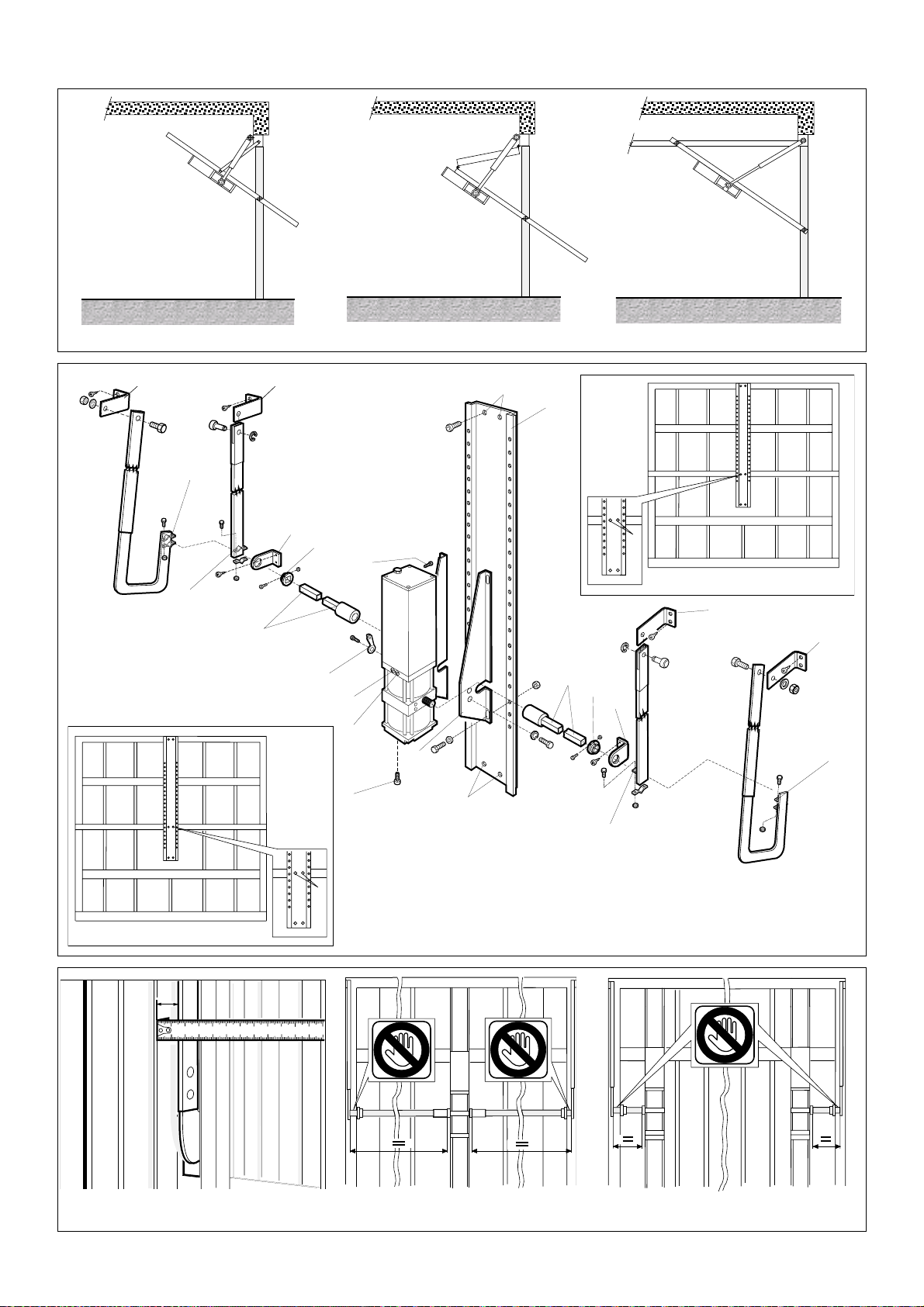
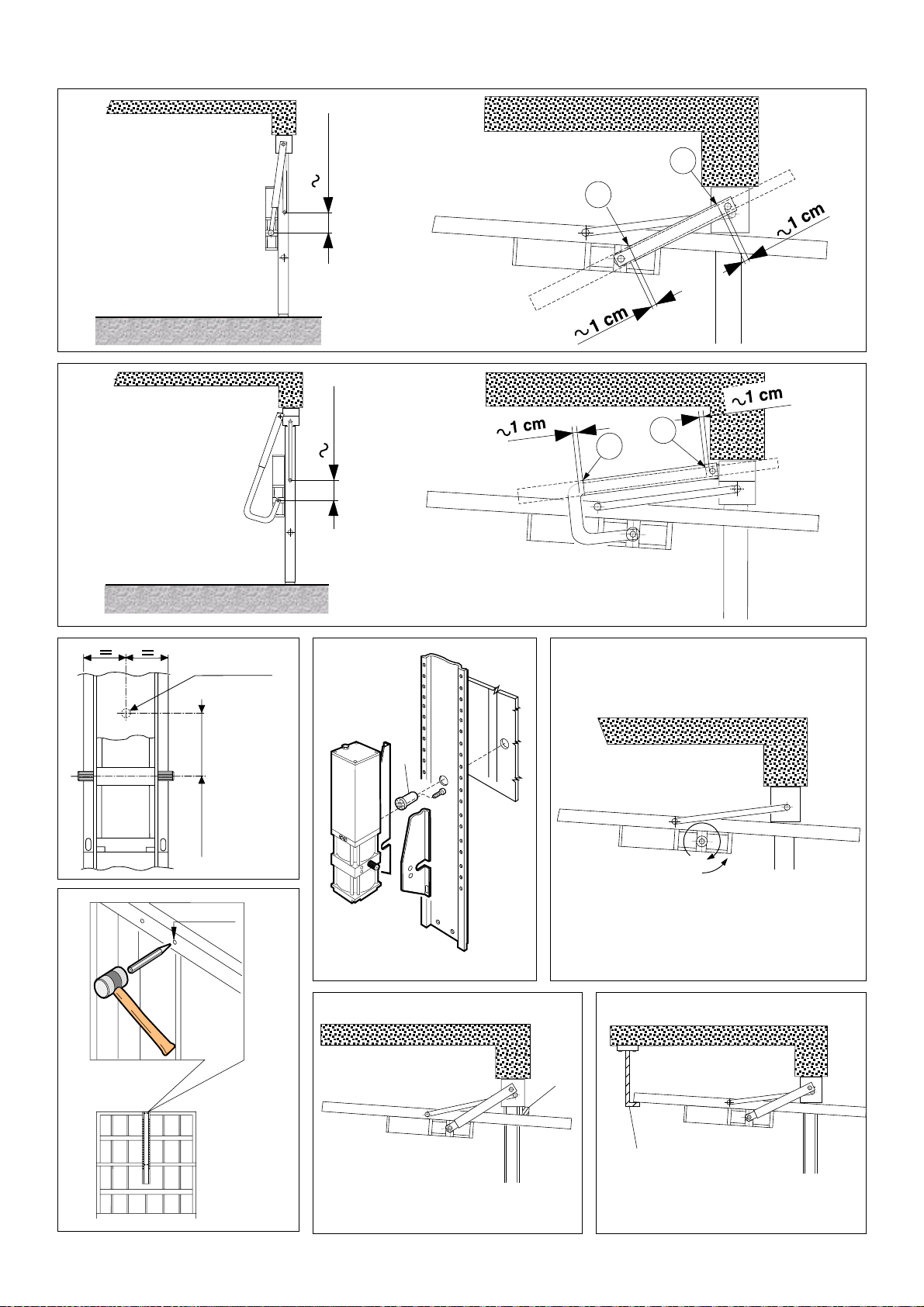
4.3. POSITIONING OF TELESCOPIC ARMS
Ensure that there is a gap (S - fig.5) of at least 15 mm
betweentheexistingcrossbarandtheframe.Thisisessential
if straight telescopic arms are to rotate correctly as shown
in fig.8.
If gap (S) is less than 15 mm, the special curved telescopic
arm must be used instead, and installed as shown in fig.9.
Refer to fig.4 to fix brackets (D) to the upright member as
close as possible to the upper support of the existing cross
bar. Fit the outer profiles of the arms. Respect maximum
door dimensions as per the technical specifications and
install either one operator (FAAC 593) at the centre of the
door (fig.6) or two operators at the sides of the door (fig.7).
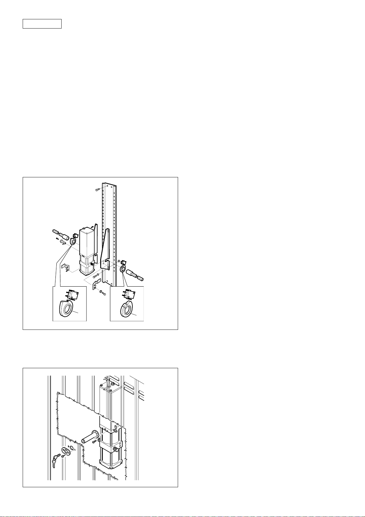
4.4. POSITIONING THE BACK PLATE / OPERATOR /
DRIVE SHAFTS
The back plate (Z) features two holes (M) and (N) which
allow for fixture to the upper cross bar of the door as
indicated in Aand Bof fig.4.
In the case of door heights of less than 2100 mm, fit the
backplate on the upper cross bar by means of (M) (see A).
With door heights above 2100 mm, fit the backplate by
means of (N) (see B, fig.4).
Drill two 6 mm holes (U) for backplate fixture onto the
centralreinforcementribbing of the door(fig.4).If the door
frameisnotsufficientlysturdy(thinsheet)usenutsandbolts.
Alternatively, use self-tapping screws.
Locate the point of rotation of the drive shaft at 10 cm
below the bottom pivot of the door’s own arm as shown in
figs. 8 and 9.
Removebleedscrew(F)andsecuretheoperatorbymeans
ofmountingbrackets(S)onthebackplateasshowninfig.4.
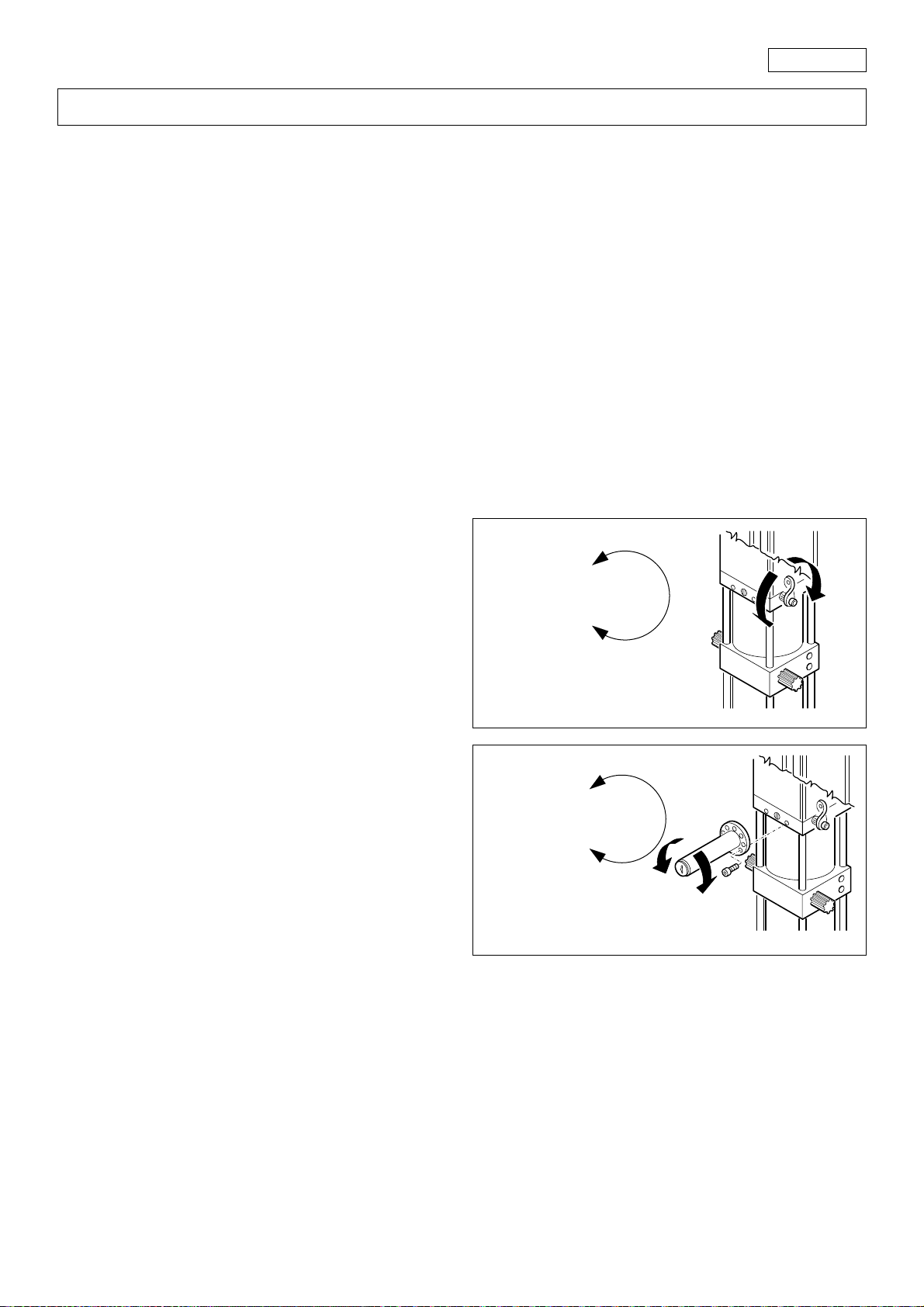
Disconnect the operator and open the garage door as
indicated in fig.12 and turn the operator drive gear in the
direction of the arrow to the piston limit. Rotate though
approx. 5° in the opposite direction.
Closethegarage door andfitdrive shafts (T- fig.4) overthe
operator drive gearsand cuttosize asshown in figs. 6/7.Fit
bushings(C)andbrackets(L)onthedriveshaftsandsecure
brackets (L) on the door reinforcement ribbing taking care
to maintain correct alignment of the drive shafts.
Straight telescopic arm:
refer to fig.8 -
Curved telescopic
arm:
refer to fig.9
Open the garage door and position the telescopic arm as
indicated in figs. 8 or 9. Cut the outer profile at point A. Cut
the inner profile of the telescopic arm at reference point B.
N.B.Leaveagapofabout1cmattheendsofbothprofiles.
Insertthedriveshafts(T)intheinnerprofileofthetelescopic
arm (Q - fig.4), already cut to size, and drill an 8 mm hole.
Secure by means of an M8 bolt.
To ensure smooth door closing operation install a cushion
pad (T - fig.14). Alternatively, to prevent garage door off-
balanceandensureoptimaloperatorfunctioning,construct
and install an “L” bracket as shown in fig.15.
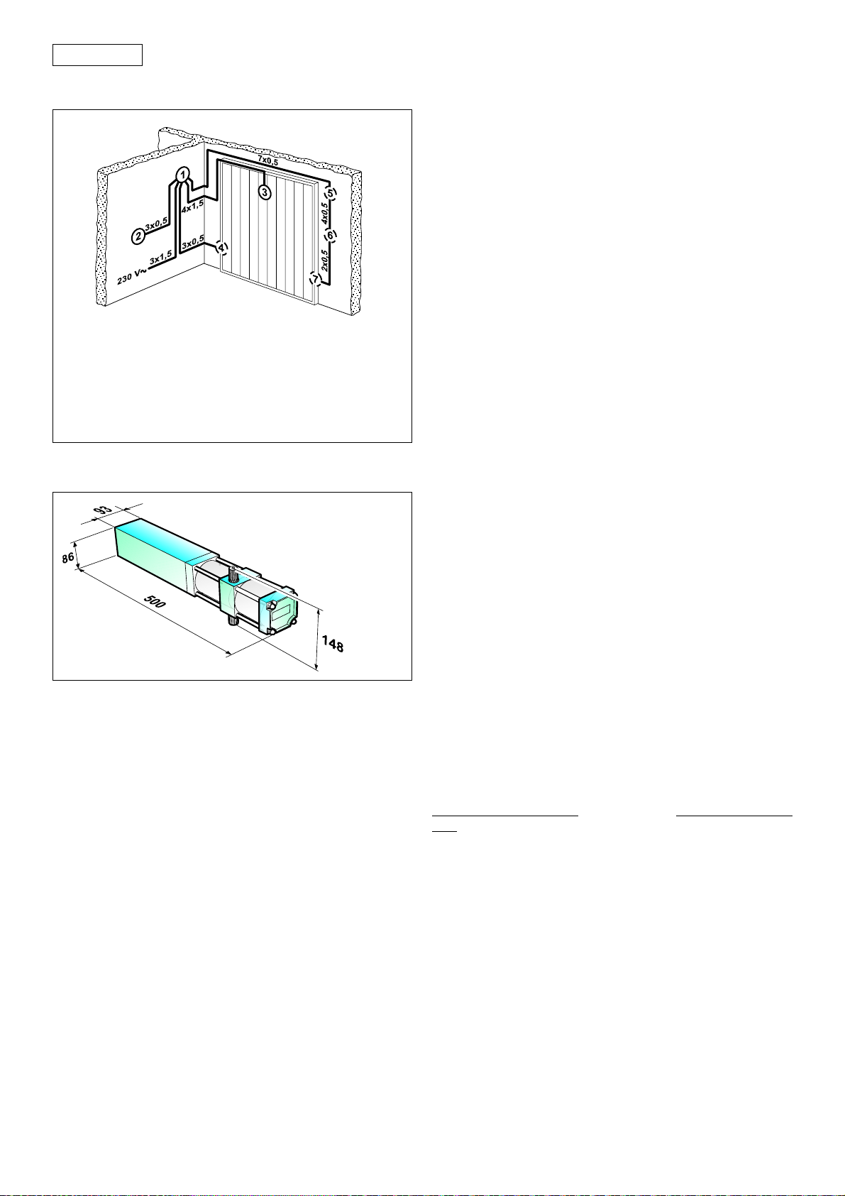
aelectronic control unit
bT 15 MP pushbutton
cFAAC 593 operator
dRx photocell
eplus radio receiver
fT 10 key-operated pushbutton
gTx photocell
3. DIMENSIONS
Fig. 18
Fig. 17
4. INSTALLATION
4.1. PRELIMINARY CHECKS
Make sure that the dimensions of the door are within the
limits stated in the technical specifications. Make sure that
the door operates smoothly and has no stiff points. If
necessary, clean the tracks and lubricate them with a
silicon based lubricant. Do not use grease. Check the
condition of all door bearings and joints. Remove the
manual door locks so that when the door is closed it will be
locked only by the automation system. Make sure that
there is a 230 Vac power supply point in the garage, and
thatitis protected byan adequate residualcurrentcircuit-
breaker.
The FAAC 593 automation system is designed to operate
various types of garage doors with counterweights. Figs. 1,
2, and 3show the most common types: canopy door,
articulated panel, horizontal tracks. Either metal blocks or
bricks can be used as counterweights, though some door
manufacturersusespringsinsteadofweights.Checkinany
case that the door pivots correctly when opening and
closing.
4.2. INSTALLATION OF OPERATOR
Accessories of the FAAC 593 are supplied in two versions:
• “Welded assembly”: welded telescopic arms, drive
shafts, and mounting brackets.

13
ENGLISH
4.5. ADJUSTING THE COUNTERWEIGHTS
The weight of the counterweights must be increased to
ensure smooth operation. If there is insufficient space to
add to the existing counterweights, remove them and
replace them with blocks of a higher specific weight. To
adjust the weights, release the operator and move the
door to half-open position (45°). The door should remain in
balance.
4.6. DOUBLE APPLICATION
For garage doors from 3.50 to 5 m wide, two 593 operators
must be used. The maximum permitted height is 3 m. Install
following the same criteria as for a single motor (fig. 7).
5. STARTUP
5.1. DIRECTION OF ROTATION
1. Disconnect the electronic control unit from the power
supply.
2. Unlock the operator, and manually move the garage
door to its half-open position (see section 6, manual
operation).
3. Relock the system (see section 6, manual operation).
4. Reconnect the power supply.
5. Send an OPEN command and check that the garage
door opens correctly.
N.B. If the first OPEN impulse causes the garage door to
close,invertthepositionof the blackandbrownwires
on the electronic control unit.
5.2. ADJUSTMENT OF OPERATION TIME
Time the opening movement. On the electronic control
unit, select an operation time that is a few seconds longer
than that of the movement you have timed, in order to
obtain optimal hydraulic locking efficiency.
5.3. ADJUSTING TRANSMITTED TORQUE
The 593 operator is fitted with an anti-crushing system to
stopdoormovementwheneveranobstacleisencountered
during movement.
Start garage door opening and adjust operator torque by
means of the green screw (V, fig.4). Repeat the same
operation for door closing by means of the red screw (R,
fig.4). Correct adjustment is obtained when the door stops
with a torque of approximately 15 kg measured on the
lower edge of the door.
To increase torque, turn the screws clockwise; to reduce
torque, turn screws anti-clockwise.
When you have completed the adjustment operations, fit
the bypass safety device on the operator by means of the
relevant screws, as shown in the figure below.
5.4. TESTING THE AUTOMATED UNIT
After completing installation, attach the danger warning
labels between the transmission tubes and the telescopic
arms (figs. 6-7). Carry out a careful functional check of the
operator and all accessories connected to it.
Give the customer the “User guide” and demonstrate how
tousetheoperatorcorrectly.Pointoutthepotentialdanger
zones of the automated unit.
6. MANUALOPERATION
Shouldtheneedarisetoactuatethegaragedoormanually
because of a power failure or malfunction, operate the
unlocking lever device as shown in fig. 20.
A customised key-operated emergency release can also
be installed outside (fig.21) (optional).
Fig. 19
Fig. 20
SBLOCCA/UNLOCK
DESBLOQUEAR
DEBLOQUE/ENTRIEGELT
BLOCCA/LOCK
BLOQUEAR
BLOQUE/VERRIEGELT
Fig. 21
SBLOCCA/UNLOCK
DESBLOQUEAR
DEBLOQUE/ENTRIEGELT
BLOCCA/LOCK
BLOQUEAR
BLOQUE/VERRIEGELT
- Insertthekeyinthelock,andturnthekeyanticlockwiseby
1 turn.
- Manually open or close the door.
7. RETURNING TO NORMAL OPERATION
Topreventanaccidentalimpulsefromactuatingthegarage
door during this operation, before you restore normal
operation, disconnect the system from the power supply.
lever (standard):
- turn the lever clockwise all the way.
customised key (optional):
- turn the key clockwise all the way;
- slowly turn the key anticlockwise up to the point where it
can be extracted.

14
ENGLISH
8. ACCESSORIES
Limit switch kit
Thelimitswitchkitmakesitpossibletostopthegaragedoor
in two specific positions.
ItcanbefittedontheFAAC593operatoronlyifthe596MPS
card has been installed on it for this function. When this
requirement has been met, proceed as follows:
1. Extract the shafts from the pinions, and mount the
cams.
2. Remove the screws holding the operator onto the
longitudinal sections, add the flat washers provided
and mount the limit switch supports.
3. Tighten the screws, and fit the limit switches into their
seats.
4. Open the garage door to the required point and turn
cam A of microswitch FCA until the microswitch is
activated.
5. Close the door to the required point and turn cam B of
microswitch FCC until the microswitch is activated.
6. Tighten the self-tapping screws on the cams.
9. MAINTENANCE
When performing maintenance always check that the by-
pass screws are set correctly, that the system is balanced
and that the safety devices operate correctly.
9.1. TOPPING UP WITH OIL
Check periodically the quantity of oil inside the tank.
For medium/low duty cycles a yearly check is sufficient; for
more severe operation it is advisable to check every 6
months.
The oil level must not be lower than the index line.
To top up, unscrew the filler cap (fig. 16) and pour in oil up
to the correct level.
Use exclusively FAAC XD 220 oil.
9.2. BLEEDING AIR FROM HYDRAULIC CIRCUIT
If the beam moves in an irregular manner, this may be due
to the presence of air in the hydraulic circuit.
If it is necessary to bleed the air, proceed as follows:
1) Check that the breather screws have been removed
(fig. 16).
2) Disassemble the lateral drive shafts from the operator.
3) Set an operating time of about 1 minute on the
electronic control unit.
4) Activate the operator electrically so that it turns to the
end of its travel in both directions of rotation.
5) Repeat this operation several times if necessary.
6) Follow the installation instructions to reassemble.
10. REPAIRS
For repairs, contact an authorised FAAC Service Centre.
FCC
B
FCA
A
Fig. 22
External release device with customised key (Figs. 10-11-23)
Thereleasedevicewithcustomisedkeymakesitpossibleto
actuate the garage door from the outside in case of a
malfunction or breakdown.
Fig. 23

1
ITALIANO
B
U
A
U
L
LCF
Z
S
C
Q
Q
T
Q
Q
T
R
V
E
DD
N
M
DD
P
Fig.2 Fig.3Fig.1
Fig.4
Fig.7Fig.6Fig.5
S

2
ITALIANO
Fig.8
Fig.9
Fig.12
Fig.11
Fig.10
Fig.13 Fig.14 Fig.15
10 cm
A
B
AB
10 cm
110 mm
ø 25 mm
N
- 5°
ø ~ 4 mm
T
L

15
ENGLISH
END-USER GUIDE
THE 593 AUTOMATION SYSTEM
Readthe end user guide carefully beforeusing the product
and keep it in a safe place for future reference.
GENERAL SAFETY INSTRUCTIONS
If correctly installed and operated, the 593 automation
system ensures a high level of safety.
However, some simple rules should be followed to avoid
accidents:
- Do not pass underneath the door while it is moving: wait
until it is completely raised.
- Do not remain stationary under the door.
- Do not stand in the vicinity of the automation system or
allow anyone else, especially children, to do so, and do
notplaceobjectsinthevicinityoftheautomationsystem.
This is particularly important during operation.
- Keep remote controls or any other control device out of
the reach of children, to prevent them from accidentally
operating the automation system.
- Donotallow children toplaywith the automationsystem.
- Do not deliberately obstruct the movement of the door.
- Donotattempttooperatethe door manually withoutfirst
unlocking it.
- In the event of a malfunction, unlock the door to allow
access and call a qualified technician for service.
- After manual operation, disconnect the electrical power
supply from the system before returning to normal
operation.
- Donotmakeanymodificationstocomponentsbelonging
to the automation system.
- Donotattempttoperformanyrepairworkortamperwith
theautomationsystem.Callqualifiedpersonnelforrepairs.
- At least once every six months, have the automation
system, the safety devices and the earth connection
checked by a qualified technician.
DESCRIPTION
The 593 automation system is an operator for
counterbalanced up-and-over doors. It is ideal for
controlling vehicle access areas up to 5 metres wide
(applicationwithdoubleoperator)andwithmediumtransit
frequencies.
Door operation is controlled by an electronic control unit
mounted in an enclosure which assures adequate
protection against atmospheric agents and can be fitted
inside the garage.
The normal position of the door is closed in a vertical
position. When the electronic control unit receives an
opening command from the remote radio control or any
other control device, it activates the hydraulic system and
causes the door to rotate upwards by 90° to the horizontal
position, thereby allowing access.
If automatic operation has been selected, the door closes
automatically after the selected pause time.
If semiautomatic operation has been selected, a second
impulse must be sent to close the door.
An open command given while the door is closing causes
the door to reverse direction of movement.
A stop command (if available) stops movement at any
time.
For detailed information on door operation in the various
operating modes, contact the installation technician.
The automation systems may be equipped with safety
devices (photocells) that prevent the door from closing
when they are darkened by an obstacle.
The593automationsystemisfittedasstandardwithananti-
crushing safety device that limits the torque transmitted to
the door.
The hydraulic system ensures that the door can be locked
in any position.
Thedoorcanbeopenedmanuallyonlyafteroperatingthe
unlocking device.
MANUAL OPERATION
Ifthedoormustbeoperatedmanuallybecauseofapower
failure or malfunction, use the unlocking device as follows.
Lever release device (see fig. 1)
External key release device (see fig.2)
Fig. 1
SBLOCCA/UNLOCK
DESBLOQUEAR
DEBLOQUE/ENTRIEGELT
BLOCCA/LOCK
BLOQUEAR
BLOQUE/VERRIEGELT
- Insert the key in the lock and turn anticlockwise by one
turn.
- Open or close the door manually.
RETURNING TO NORMAL OPERATION
Topreventan accidental impulse fromactivatingthe door
duringthisoperation,beforereturningtonormaloperation,
turn off the system’s electrical power supply.
Lever release device (see fig. 1)
External key release device (see fig.2)
- turn the key clockwise until it stops.
- turn the key anticlockwise very slowly to the point where
it can be removed.
Fig. 2
SBLOCCA/UNLOCK
DESBLOQUEAR
DEBLOQUE/ENTRIEGELT
BLOCCA/LOCK
BLOQUEAR
BLOQUE/VERRIEGELT


Timbro del Rivenditore:/Distributor’s Stamp:/Timbre de l’Agent:/ Fachhändlerstempel:/Sello del Revendedor:
Le descrizioni e le illustrazioni del presente manuale non sono impegnative. La FAAC si riserva il diritto,
lasciando inalterate le caratteristiche essenziali dell’apparecchiatura, di apportare in qualunque
momento e senza impegnarsi ad aggiornare la presente pubblicazione, le modifiche che essa ritiene
convenientipermiglioramenti tecnici o per qualsiasi altraesigenzadicaratterecostruttivoocommer-
ciale.
The descriptions and illustrations contained in the present manual are not binding. FAAC reserves the
right, whilst leaving the main features of the equipments unaltered, to undertake any modifications it
holdsnecessaryforeithertechnicalorcommercialreasons,atanytimeandwithoutrevisingthepresent
publication.
Lesdescriptionsetlesillustrationsduprésentmanuelsontfourniesàtitreindicatif.FAACseréserveledroit
d’apporter à tout moment les modifications qu’elle jugera utiles sur ce produit tout en conservant les
caractéristiques essentielles, sans devoir pour autant mettre à jour cette publication.
Die Beschreibungen und Abbildungen in vorliegendem Handbuch sind unverbindlich. FAAC behält
sich das Recht vor, ohne die wesentlichen Eigenschaften dieses Gerätes zu verändern und ohne
VerbindlichkeiteninBezugaufdieNeufassungdervorliegendenAnleitungen,technischbzw.konstruktiv/
kommerziell bedingte Verbesserungen vorzunehmen.
Las descripciones y las ilustraciones de este manual no comportan compromiso alguno. FAAC se
reserva el derecho, dejando inmutadas las características esenciales de los aparatos, de aportar, en
cualquiermomentoysincomprometerseaponeraldíalapresentepublicación,todaslasmodificaciones
queconsidere oportunas para elperfeccionamiento técnicoo paracualquier otro tipode exigencia
de carácter constructivo o comercial.
FAAC S.p.A.
Via Benini, 1
40069 Zola Predosa (BO) - ITALIA
Tel.: 051/6172411 - Tlx.: 521087
Fax: 051/758518
FAAC per la natura
• La presente istruzione è realizzata al 100% in carta riciclata.
• Non disperdete nell'ambiente gli imballaggi dei componenti dell'automazione bensì selezionate
i vari materiali (es. cartone, polistirolo) secondo prescrizioni locali per lo smaltimento rifiuti e le
norme vigenti.
FAAC for the environment
• The present manual is produced in 100% recycled paper
• Respecttheenvironment.Disposeofeachtypeofproductpackagingmaterial(card,polystyrene)
in accordance with the provisions for waste disposal as specified in the country of installation.
FAAC der Umwelt zuliebe
• Vorliegende Anleitungen sind auf 100% Altpapier gedruckt.
• Verpackungsstoffe der Antriebskomponenten (z.B. Pappe, Styropor) nach den einschlägigen
Normen der Abfallwirtschaft sortenrein sammeln.
FAAC écologique
• La présente notice a été réalisée 100% avec du papier recyclé.
• Ne pas jeter dans la nature les emballages des composants de l’automatisme, mais sélectionner
les différents matériaux (ex.: carton, polystyrène) selon la législation locale pour l’élimination des
déchets et les normes en vigueur.
FAAC por la naturaleza.
• El presente manual de instrucciones se ha realizado, al 100%, en papel reciclado.
• Los materiales utilizados para el embalaje de las distintas partes del sistema automático (cartón,
poliestireno)nodebentirarsealmedioambiente,sinoseleccionarseconformealasprescripciones
locales y las normas vigentes para el desecho de residuos sólidos.
para la naturaleza
100% papel reciclado
ist umweltfreundlich
100% Altpapier
pour la nature
papier recyclé 100%
for nature
recycled paper 100%
carta riciclata 100%
per la natura
732009- Rev. A
Other manuals for 593
1
Table of contents
Other FAAC Garage Door Opener manuals
Popular Garage Door Opener manuals by other brands

Chamberlain
Chamberlain 882LMW quick start guide

Chamberlain
Chamberlain 1145-1/3HP owner's manual

Vimar
Vimar ELVOX ESM7 Installation and operation manual

Brano Industries
Brano Industries Aladdin II Setup instruction and users manual

Keyautomation
Keyautomation SEKUR FT43 manual

G-Force
G-Force SL 2000 DC2 Installation and setup instructions

Erreka
Erreka MAXI Quick installation and programming guide

Zap
Zap 8825-R4 installation instructions

Chamberlain
Chamberlain Power Drive Security+ PD752DS owner's manual

Chamberlain
Chamberlain RJO20 manual

DoorHan
DoorHan RSD01S Series Service book

Visonic
Visonic X-pervisio 1000 Assembly and user instructions