FAAC 844 MC-R User manual

12
ENGLISH ENGLISH
EC MACHINE DIRECTIVE COMPLIANCE DECLARATION
(DIRECTIVE 89/392 EEC,APPENDIX II,PART B)
Manufacturer: FAAC S.p.A.
Address: Via Benini, 1
40069 - Zola Predosa
BOLOGNA - ITALY
Hereby declares that: the 844 MC-R automation system
•isintendedtobeincorporatedintomachinery,ortobeassembledwithother
machinery to constitute machinery in compliance with the requirements of
Directive 89/392 EEC, and subsequent amendments 91/368 EEC, 93/44 EEC
and 93/68 EEC;
•complieswiththeessentialsafetyrequirementsinthefollowingEECDirectives:
73/23 EEC and subsequent amendment 93/68 EEC.
89/336 EEC and subsequent amendments 92/31 EEC and 93/68 EEC.
and furthermore declares that unit must not be put into service until the
machinery into which it is incorporated or of which it is a component has
been identified and declared to be in conformity with the provisions of
Directive89/392EECandsubsequentamendmentsenactedbythenational
implementing legislation.
Bologna, 1 January 1997
Managing
Director
A. Bassi

13
ENGLISH
ENGLISH
IMPORTANT NOTICE FOR THE INSTALLER
GENERAL SAFETY INSTRUCTIONS
1) WARNING!Forreasonsofsafety,alltheinstructionsinthismanualmustbeobservedscrupulously.Improperinstallation
or misuse of the product may result in serious injury.
2) Read the instructions carefully before installing the product.
3) Packaging material (plastic, polystyrene etc.) is a potential hazard and must be kept out of reach of children.
4) Keep these instructions for future reference.
5) This product has been designed and manufactured only for the use stated in this manual. Any use other than that
expressly indicated may result in damage to the product and/or risk of injury.
6) FAACS.p.A.shallnotbeliableforanydamageorinjurycausedbyimproperuseoftheautomationorbyanyuseother
than that for which it is intended.
7) Do not install this device in explosive atmospheres: the presence of flammable gas or fumes is a serious hazard.
8) Mechanical structural elements must comply with UNI8612, CEN pr EN 12604 and CEN pr EN 12605 standards.
ForcountriesoutsidetheEC,mechanicalstructuralmust complywiththe abovestandardsin additiontoany national
safety standards, in order to obtain a reasonable degree of safety.
9) FAACcannot be held responsiblefor failureto observe technicalstandards inthe construction ofthe gateson which
the automation is installed, or for any deformation of the gates which may occur during use.
10) Installation must comply with UNI8612, CEN pr EN 12453 and CEN pr EN 12635.
The degree of safety of the automation must be C+D.
11) Before carrying out any operations on the system, disconnect the electrical power supply.
12) Install a multi-pole switch on the supply line to the automation with a contact opening distance of 3 mm or more. We
recommend the use of a 6A thermal magnetic circuit breaker with multi-pole switching.
13) Ensure that a residual current device with a trip threshold of 0.03A is installed upstream of the automation system.
14) Check that the earthing system is installed correctly and is efficient. Connect the metal parts of the gate and the
yellow/green wire of the operator to the earthing system.
15) The automation is fitted with an anti-crushing safety system consisting of a torque control device which, in all cases,
must be used in conjunction with other safety devices.
16) Thesafetydevices(e.g.photocells,safetyedges,etc.)protectareaswherethereisamechanicalmovementhazard,
e.g. crushing, entrapment and cutting.
17) Each installation must be fitted with at least one flashing light (e.g. FAAC LAMP, MINILAMP etc.) and a warning sign
suitably fixed to the gate, in addition to the safety devices as per point 16 above.
18) FAAC cannot be held responsible for the safe and correct operation of the automation in the event that parts other
than FAAC original parts are used.
19) Use only FAAC original spare parts for maintenance operations.
20) Do not carry out any modifications to automation components.
21) The installer must supply all information regarding manual operation of the system in the event of an emergency and
provide the end-user with the "End-user Guide" supplied with the product.
22) Do not allow any persons, especially children, to stand in the vicinity of the automation when in operation.
23) Keep the remote radio controls and any other control devices out of the reach of children to prevent accidental
operation of the automation.
24) The end-user must not attempt to repair or adjust the automation. These operations must be carried out exclusively
by qualified personnel.
25) Any operations not explicitly described in these instructions are not permitted.

14
ENGLISH ENGLISH
These instructions apply to the following models:
844 MC-R
The FAAC model 844MC-R automation for sliding gates is an
electromechanical operator which transmits movement to
the gate leaf by means of a rack and pinion coupled in an
appropriate manner to the sliding gate.
The reversible system allows the gate to be moved manually
when the motor is not in operation. An electric lock must
therefore be installed to ensure that the gate cannot move
when closed.
The gear motor is equipped with an adjustable mechanical
clutch which affords the necessary anti-crushing safety. A
convenient manual release device allows the gate to be
operated in the event of mechanical problems with the gear
motor. The electronic control unit may be housed inside the
operator or in a separate box.
The automation 844MC-R has been designed and built for
vehicle access control. Do not use for any other purpose.
1. DESCRIPTION AND TECHNICAL CHARACTERISTICS
AUTOMATION 844 MC-R & 844 MPSR
TABLE 1 TECHNICAL SPECIFICATIONS OF 844MC-R OPERATOR
1.1. MAXIMUM UTILISATION CURVE
Thecurveallowsthemaximumworkingtime(T)tobeobtained
as a function of duty cycle (F).
E.g.: the 844 MC-R operators can work continuously at a duty
cycle of 30%.
To ensure good operation, keep to the field of operation lying
below the curve.
Important:Thecurverefers toatemperature of24°C.Exposure
to direct sunlight can result in a reduction in duty cycle to as
low as 20%.
Calculating duty cycle
The duty cycle is the percentage of effective working time
(opening+closing)withrespecttothetotalcycletime(opening
+ closing + pause times).
It is calculated using the following formula:
Ta + Tc
%F = X 100
Ta + Tc + Tp + Ti
where:
Ta = opening time
Tc = closing time
Tp = pause time
Ti =
interval between one complete cycle and the next.
Graph of duty cycle
Fig. 1
aFixing angle bars
bPinion
cInductive proximity limit switch
dSpare fuse housing
eElectronic control unit enclosure
f844MPSR electronic control unit
gBreather screw
hCapacitor
iAdjusting screw for anti-crushing clutch
jBore for access to oil filler cap
kCover lock operated with triangular key
lOperator ground connection
mBores for passage of connection cables
nRelease lever
oFixing bar cover
MODEL 844
Power supply 230V~ (+ 6 % - 10 %) 50Hz
Power consumption (W) 550
Reduction ratio 3÷ 29
No. of pinion teeth Z12
Rack 4 module pitch 12,566
Max. thrust daN 83 (Z12)
Max. torque (Nm) 20
Winding thermal protection 140 °C
Duty rating 30 % (see graph)
Oil quantity (l) 1,8
Type of oil FAAC XD 220
Temperature range -20 to +55 °C
Gear motor weight (kg) 15
Housing protection IP 55
Max. gate weight (kg) 1000 (Z12)
Gate speed (m/min) 11.6 (Z12)
Max. gate length 49m (Z12)
Clutch bidisk in oil bath
Housing treatment cataphoresis
Limit switches
inductive with stop plates
Gear motor dimensions LxHxD (mm) see Fig. 2
Electric motor technical specifications
Motor speed (rpm) 750
Power consumption (W) 550
Current draw (A) 2.5
Surge condenser 25µF
Power supply 230 Vac (+ 6 % - 10 %) 50Hz
b
a
c
d
e
f
g
h
i
j
k
l
m
n
o
10
20
30
40
50
60
70
80
90
100
012345678910
10 11 12
Percentuale
d
i lav. %
Tiempo
(
h
)
% Duty cycle % Fréquence
d'utilisation % Benutzungs-
frequenz % Frecuencia
de utilización
Zeit
(
Std.
)
Temps
(
h
)
Time
(
h
)
Tempo
(
h
)

15
ENGLISH
ENGLISH
a844 MC-R operator
bPhotocells
cKey switch
dFlashing light
eRadio receiver
fElectric lock Fig. 3
2. DIMENSIONS
Fig. 2
Values are expressed in mm.
3. ELECTRICAL SET-UP (standard system)
4. INSTALLING THE AUTOMATION
4.1. PRELIMINARY CHECKS
For safe, correct operation of the automation, make sure that
the following requirements are met:
• The gate’s structure must be suitable for automation. Take
specialcare toensure that thewheels are largeenough to
support the full weight of the gate, that a top runner is
installed and that physical stops are fitted to prevent the
gate from coming off the runner.
• Make sure that the bottom runner is perfectly horizontal. If
itslopes,thefactthatthegearmotorisreversiblemayallow
the gate to move on its own.
• The characteristics of the ground must ensure sufficient
support for the foundation plinth.
• Theremustbenopipesorelectricalcablesintheareatobe
dug for installing the foundation plinth.
• If the gear motor is located in a vehicle transit area, it is
advisable to provide protection against accidental colli-
sions.
• Check that the gear motor has an efficient earth connec-
tion.
4.2. INSTALLING THE BASE PLATE
1) Assemble the base plate as shown in Fig.4.
2) The base plate must be positioned as shown in Fig. 5 (right-
handedclosure(right-handedclosure)orFig.6(left-handed
closure) to ensure that the pinion and rack mesh correctly.
3) PrepareafoundationplinthasshowninFig.7andinstallthe
base plate providing one or more conduits for electrical
cables. Use a level to check that the plate is perfectly
horizontal and wait for the cement to set.
4) Laythe electrical cablesfor connection tothe accessories
and the electricity supply as shown in Fig. 3. For ease of
connection, ensure that the cables protrude by about
45 cm from the hole in the base plate (Figs. 5-6 ref.1).
Fig. 4
Fig. 5
Fig. 6
11
11
1
11
11
1
Fig. 7
385
280
191
158
209
63
225
90°
49
0÷50
49
0÷50 155
90°

16
ENGLISH ENGLISH
4.3. MECHANICAL INSTALLATION
1) Fix the angle bars and the vibration dampers to the
operator as shown in Fig. 8.
2) Open the cover of the operator using the triangular key
supplied (Fig. 9).
The cover will remain in the open position thanks to a
locking system.
3) Fix the operator to the base plate using the nuts and
washers supplied (Fig. 10).
Duringthisoperation,routethecablesthroughtheconduit
in the lower half of the operator.
To access the electronic equipment, route the cables
through the holes provided (13, Fig. 1) using the grommets
supplied.
4) Adjust the height of the feet and the distance from the
gate as shown in Fig. 11.
5) Secure the gear motor onto the base plate by tightening
the nuts as shown in Fig. 12.
6) Remove the breather screw as shown in Fig. 13 and keep it
in a safe place.
Fig. 11
Fig. 12
Fig. 9
Fig. 8
Fig. 10
4.4. FITTING THE RACK
4.4.1. WELD-ON STEEL RACK (Fig.14)
1) Mount the three threaded bushes
on the rack element, positioning
themintheupperpartoftheslot.In
this way the play provided by the
slotwillallow forfuture adjustment.
2) Slide the gate leaf manually to the
closed position.
3) Rest the first rack element level on
the pinion and weld the first
threaded bush onto the gate as
shown in Fig. 16.
4) Slide the gate manually making sure that the rack rests on
the pinion. Weld the second and third bushes.
5) Position another rack element next to the first and use a
sectionofracktosettheteethofthetwoelementsinphase
as shown in Fig. 17.
6) Open the gate manually and weld the three threaded
bushes. Proceed in this manner until the rack covers the
entire length of the gate.
Fig. 14
Fig. 13
5 max
43
104 (Z12)
64
49
15 ÷ 32

17
ENGLISH
ENGLISH
connections from the 844 MPS electronic control unit to the chosen
accessories.
Always route the power supply cables separately from the control
andsafetycables(keyswitch,receiver,photocells,etc.).Useseparate
conduits to avoid any interference.
If the 844 MPSR electronic control unit is installed inside the gear
motor, remove the 844 INTERFACE card, which serves only if the
control unit is installed in a separate box.
5.1.1. 844MPSR ELECTRONIC CONTROL UNIT
TABLE 2 TECHNICAL CHARACTERISTICS OF 844MPSR
Power supply 230V~ (+6 -10 %) 50Hz
Motor max. load 650 W
Accessories power supply 24Vdc/24V~
Accessories max. load 500 mA
Warning light power supply 24V~ (5W max)
Temperature range - 20°C + 55°C
Fuses transformer primary - motor - accessories
Quick connectors - for decoding cards or RP receivers-
- capacitor - limit switch -
Inputs OPEN/STOP/CLOSING SAFETY/LIMIT-SWITCH
Outputs warning light - flashing light
motor - 24Vdc/24V~power supply for accessories
pause time (5-10-15-30-60-120-180 sec.)
Logic programming (automatic A1/S1/S2 - semiautomatic E1)
pre-flashing
Motor braking Adjustable by trimmer
Safety timing 255 sec.
5. 1. 2. 844MPS LAY-OUT
TABLE 3 844MPS Control unit components
F1 Fast-acting fuse F1 5x20 F5A/250V (motor )
F2 Time delay fuse F2 5x20 T1.6A/250V (accessories)
F3 Time delay fuse F3 5x20 T250mA/250V (transformer)
P1 RESET button
TR1 Braking adjustment trimmer
DS1 Programming dipswitches
Led Input status indicator LEDs
J1 Quick connector for decoding cards/RP receiver
J2 Low voltage inputs/accessories terminal block
J3 Quick connector for limit switch (LH closure)
J4 Quick connector for limit switch (RH closure)
J5 Motor output terminal block
J6 Quick connector for capacitor
J7 Flasher unit output terminal block (230V~ max 60W)
J8 Line input terminal block
Fig. 19
4.4.2.SCREW-ON STEEL RACK (Fig. 15)
1)
Slidetheleafmanuallytotheclosed
position.
2) Rest the first rack element level on
the pinion and insert the spacer in
the upper part of the slot between
the rack and the gate.
3) Mark the point to be drilled on the
gate. Drill a 6.5 mm diameter hole
and thread using 8 mm screw taps.
Tighten the bolt.
4) Slide thegate manuallymaking sure
that the rack rests on the pinion and repeat the operations of
point 3.
5) Place another rack element next to the first and use a section of
racktosettheteethof thetwoelementsinphase asshowninFig.
17.
6) Slide the gate manually and secure the rack element in the
same manner as the first element. Proceed in this manner until
the rack covers the entire length of the gate.
Fig. 15
Fig. 16
Fig. 17
Notes on the installation of the rack
• Checkthatnoneoftherackelementscomeoffthepinionduring
the movement of the gate.
• Do not weld the rack elements either to the spacers or to each
other.
• After installing the rack, lower the position of the gear motor by
adjusting the feet (Fig. 18) by about 1.5
mmto ensure correct meshing with the
pinion.
• Checkmanually thatthe gatereaches
the mechanical travel limits correctly
and that it does not encounter friction
during its travel.
• Do not use grease or other lubricants
between the pinion and the rack.
5. START-UP
5.1. CONNECTION TO ELECTRONIC CONTROL UNIT 844
MPSR
Ü
Always disconnect the electrical power supply before carrying
out any operations on the control unit (connections, program-
ming, maintenance).
Warning: On disconnecting connector J6, high voltages may be
present on the capacitor output.
Observe points 10, 11, 12, 13 and 14 in the GENERAL SAFETY
INSTRUCTIONS.
As shown in Fig. 3, lay the conduits and make the electrical
Fig. 18
1.5
P1
RESET
TR1
BRAKE
F2
F1
F3
J7
J8
J6
J5
J4J3
J2
CH-DXCH-SX
J1
DS1
RL1
RL2
IC1
1 2 3 4 5 6 7 8 9
844MPSR
TR1 P1 F2
J1
DS1
F1F3
Led
J2 J5 J7
J3 J4 J6 J8

18
ENGLISH ENGLISH
5.2. DESCRIPTION
5.2.1. CONNECTOR J1
The connector J1 is used for the quick connection of
MINIDEC,DECODER, RP RECEIVER boards (Figs. 21,22,23).
Accessory boards are to be inserted with their component
sides facing the inside of the 844MPSR electronic control unit.
Always disconnect the power supply before inserting or
removing accessory boards.
Fig. 20
5. 1. 3. ELECTRICAL CONNECTIONS
Fig. 23
Fig. 22Fig. 21
844
MPSR
844
MPSR
844
MPSR
5.2.2. TERMINAL BLOCK J2 (low voltage)
1
&
5
=Common/Negative of accessory power supply (-)
2 = OPEN control device (N.O.)
Any control device (pushbutton,detector,..) which,
on closing the contact,relays an open and/or close
impulse to the gate.
To install more than one Open control device, con-
nect the N.O.contacts in parallel.
3 = STOP control device (N.C.)
Any control device (e.g. pushbutton) which, on
opening a contact,stops the movement of the gate.
To install more than one Stop control device, con-
nect the N.C.contacts in series.
If no Stop control devices are to be connected,
place a jumper across the input and the common
terminal (terminal 1 or 5).
4 = FSW closure safety device (N.C.)
Any control device (photocells, safety edges, mag-
netic loops) with an N.C. contact which interrupts
the movement of the gate when an obstacle is de-
tected within the protected area.
The task of the closure safety device is to safeguard
the area occupied by the gate during the closing
movement.
The intervention of safety devices during gate clo-
sure causes the direction of gate movement to be
reversed. These devices do not intervene during
gate opening movements.If a closure safety device
is tripped when the gate is open or during a pause
time,they will prevent gate closure.
To install more than one safety device,connect the
N.C.contacts in series.
If no closure safety devices are to be installed,place
a jumper across this input and the common termi-
nal (terminal 1 or 5).
6
&
8
= 24V~ accessories power supply
The maximum load of the accessories is 500 mA.
To calculate power draw,refer to the instructions for
the individual accessories.
If the jumper LK1 is broken, the 24V~ accessories
power supply is no longer available (Fig.28).
7 = 24Vdc accessories power supply positive (+)
The maximum load of the accessories is 500 mA.
To calculate power draw,refer to the instructions for
the individual accessories.
9 = Electric lock output (12 Vac)
For operation of the electric lock, refer to the
dipswitch settings.If two electric locks are installed,
they must be connected in series.
5.2.3. CONNECTORS J3-J4 (limit switch)
J3 = Connection of limit switch for left-hand closure
J4 = Connection of limit switch for right-hand closure
Refer to Figs. 24-25 for quick connection of the inductive limit
switch sensor for the corresponding gate closure direction.
J4J3
J2
CH-DXCH-SX
1 2 3 4 5 6 7 8 9
M
1
2
1
2
3
4
5
J5 J6 J8 J7
230V~ 50Hz
(+6% -10%)
C
35µF
FAACLAMP
MINILAMP
Elettroserratura
Electric lock
Electroserrure
Elektrochloss
Electrocerradura
844MPSR
LN (L)
FINECORSA
LIMIT SWITCH
FIN DE COURSE
ENDSCHALTER
FIN DE CARRERA
1
2
3
4
5
1
2
Altre sicurezze
Other safeties
Autres sécurités
Andere Sicherheiten
Otros disp. seg.
ab
MINIDEC
SL/DS
PLUS
844MPS
DECODER
SL/SLP/DS
844MPS
844MPS

19
ENGLISH
ENGLISH
Fig. 27
5.2.4. TERMINAL
BLOCKJ5(high
voltage)
Terminal block for motor
connection.
Connect the wires to the
terminals of J5 as shown
in Fig.26.
B
LACK
AND
B
ROWN
WIRES
=
electric motor supply
phases
B
LUE
WIRE
= electric motor
common
5.2.5. CONNECTOR J6 (high voltage)
Connector for quick connection of the capacitor.
5.2.6. TERMINAL BLOCK J7 (high voltage)
230V~ terminal block for connection of the flashing light (max
60W).
5.2.7. TERMINAL BLOCK J8 (high voltage)
Terminalblock for connection of the 230V~ 50Hz power supply
(L=Line N=Neutral)
Connect the earth wire to the operator as shown in Fig.27.
5.2.8. INDICATOR LEDS
5 LEDs on the board indicate the status of the terminal inputs
(see Table 4 and fig.28):
L
ED
ON
= contact closed
L
ED
OFF
= contact open
TABLE 4 MEANING OF STATUS INDICATOR LEDS
LED ON OFF
OPEN
Command active Command not active
STOP
Command not active Command active
FSW
Safeties disengaged Safeties engaged
FCC
Closing limit disengaged Closing limit engaged
FCA
Opening limit disengaged Opening limit engaged
Fig. 25
Fig. 24
5.3. INSTALLING ELECTRIC LOCK
Since the gear motor allows the gate to be moved manually
when the motor is not running, an electric lock must be
installed to ensure that the gate remains locked when closed.
It must be positioned vertically on the upper guide upright (if
the height of the gate permits) to allow it to be released from
both inside and outside
(fig.29).
Fig. 28
Closure
Fig. 29
Upper guide
upright
Electric lock Post Lock plate
Fig. 31
J4J3
CH-DXCH-SX
844MPSR
J5
J4J3
CH-DXCH-SX
844MPSR
J5
M
J5
Fig. 26
J2
1 2 3 4 5 6 7 8 9
BROWNBLACK
BLUE
Fig. 26

20
ENGLISH ENGLISH
min. 25 mm
(1) With the pre-flashing selected, movement starts after 5 seconds.
(2) If the impulse is sent during pre-flashing, the timer is reset to zero.
5.5. FAULT CONDITIONS
The following conditions effect normal operation of the
automation:
amicroprocessor error
bintervention of the electronic safety timer (interruption of
operation after continuous working time exceeds 255
seconds).
cdisconnection of the limit switch cable connector
• Conditions aand bhave the sole effect of causing the
automation to stop.
• Condition c(indicated by the fact that both LEDs FCA
and FCC are off) prevents the card from operating:
normal operation is only resumed after the cause of the
IMPULSES
LOGICA A1
SAFETY
no effect
freezes pause until
disengagement
inverts motion
no effect
no effect
STOP
no effect
stops counting
stops
stops
no effect
GATE STATUS
CLOSED
OPEN
CLOSING
OPENING
STOPPED
OPEN
opens and recloses after
pause time (1)
recloses after 5 s (2)
inverts motion
no effect
recloses (1)
TABLE 5 LOGICA A1 (AUTOMATIC)
•
Mount the electric lock vertically on the upper guide
upright (or on the support bracket).
•
Closethegate(toabout2cmfromthemechanicaltravel
stop) and provisionally mount the lock plate. Fix perma-
nentlyonlyaftertestingthecontrolunit,checkingthatthe
closurelimitswitchworksandadjustingthe intensityofthe
brakingeffect.
5.4. DIPSWITCH SETTINGS
Toprogramtheoperationoftheautomation,setthedipswitches
as shown in the diagram above.
Press the RESET button after all programming operations.
Operating logics
There are four operating logics available:
A1 = Automatic S1 = Safety
S2 = Safety Plus E = Semi-automatic
Operation of the different logics is described in tables 5-6-7-8.
Pause time
The pause time is amount of time the gate remains open
beforeitre-closeswhenanautomaticcontrollogicisselected.
Pause times include the pre-flashing time, if selected.
Operation of electric lock(s)
Allowsyoutochoosewhethertheelectriclockistobeactivated
only before opening or also before closing. In both cases the
lockisreleasedonlywhentherespectivelimitswitchisengaged
(e.g.itis releasedbeforeopeningonlyiftheclosurelimitswitch
is activated).
Pre-flashing
Itispossibletoselect5secondspre-flashingoftheflashinglight
before any gate movement. This serves to warn any persons in
the vicinity that the gate is about to start moving.
Install as follows:
•
Makesurethattheupperguideuprightis largeenoughto
allow the electric lock to be mounted vertically; if it is not,
install a rugged support bracket.
•
Makesurethattheclearancebetweentheloweredgeof
the upper guide upright and the upper edge of the gate
is sufficient to allow the lock plate to be installed and
allows the bolt to work correctly (see fig.30).
N.B.:ThevaluesmarkedrefersolelytotheFAACV75code
712654 lock and the FAAC code 720329 lock plate
Lock plate
Electric lock Upper guide
upright(section)
Closure Fig. 30
Pre-flashing SW6
Yes ON
No OFF
123456
Operation of electric lock(s)
SW5
Release only before opening (1 electric lock)
ON
OFF
Release before opening and release before
closing (2 electric locks required)
Logica SW1 SW2
E1 ON ON
A1 ON OFF
S2 OFF ON
S1 OFF OFF
Pause time (sec)
Logic
A1 - S2 S1 SW3 SW4
515ONON
10 30 OFF ON
30 60 ON OFF
120 180 OFF OFF
ON
OFF
LOGIC S1 IMPULSES
GATE STATUS
CLOSED
OPEN
CLOSING
OPENING
STOPPED
OPEN
opens and recloses after
pause time (1)
recloses immediately
(1 and 2)
inverts motion
inverts motion
recloses (1)
STOP
no effect
stops counting
stops
stops
no effect
SAFETY
no effect
recloses after 5 s
fromdisengagement
inverts motion
no effect
no effect
TABLE 6 LOGIC S1 (SAFETY)
LOGIC S2 IMPULSES
STOP
no effect
stops counting
stops
stops
no effect
GATE STATUS
CLOSED
OPEN
CLOSING
OPENING
STOPPED
OPEN
opens and recloses after
pause time (1)
recloses immediately
(1 and 2)
inverts motion
inverts motion
recloses (1)
SAFETY
no effect
freezes pause until
disengagement
stops and inverts motion
whendisengaged (1)
no effect
no effect
TABLE 7 LOGIC S2 (SAFETY PLUS)
TABLE 8 LOGIC E1 (SEMI-AUTOMATIC)
SAFETY
no effect
no effect
inverts motion
no effect
no effect
GATE STATUS
CLOSED
OPEN
CLOSING
OPENING
STOPPED
OPEN
opens (1)
recloses (1)
inverts motion
stops
recloses (reopens when safety
devices are engaged) (1)
STOP
no effect
no effect
stops
stops
no effect
IMPULSES
LOGIC E1

21
ENGLISH
ENGLISH
Fig. 34
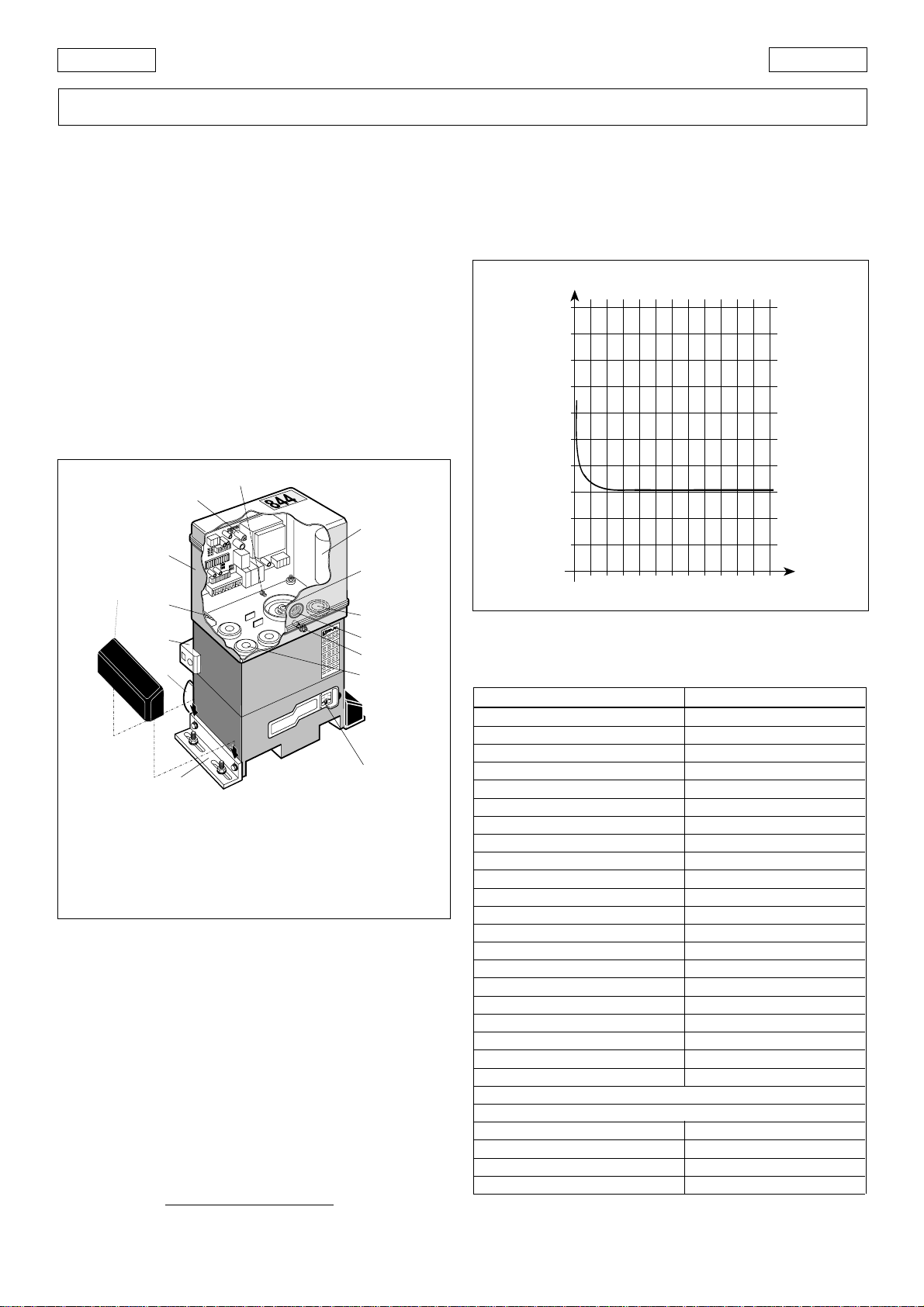
5.7. TORQUE ADJUSTMENT
The 844 MC-R automation system is equipped with an anti-
crushing mechanical clutch which stops the opening/closing
movement when the gate encounters an obstacle.
Whentheobstacleisremoved,thegateresumesitsmovement
until the relevant limit switch trips or the safety time (TIME OUT)
is exceeded.
This torque limiter must be set in compliance with current
standards.
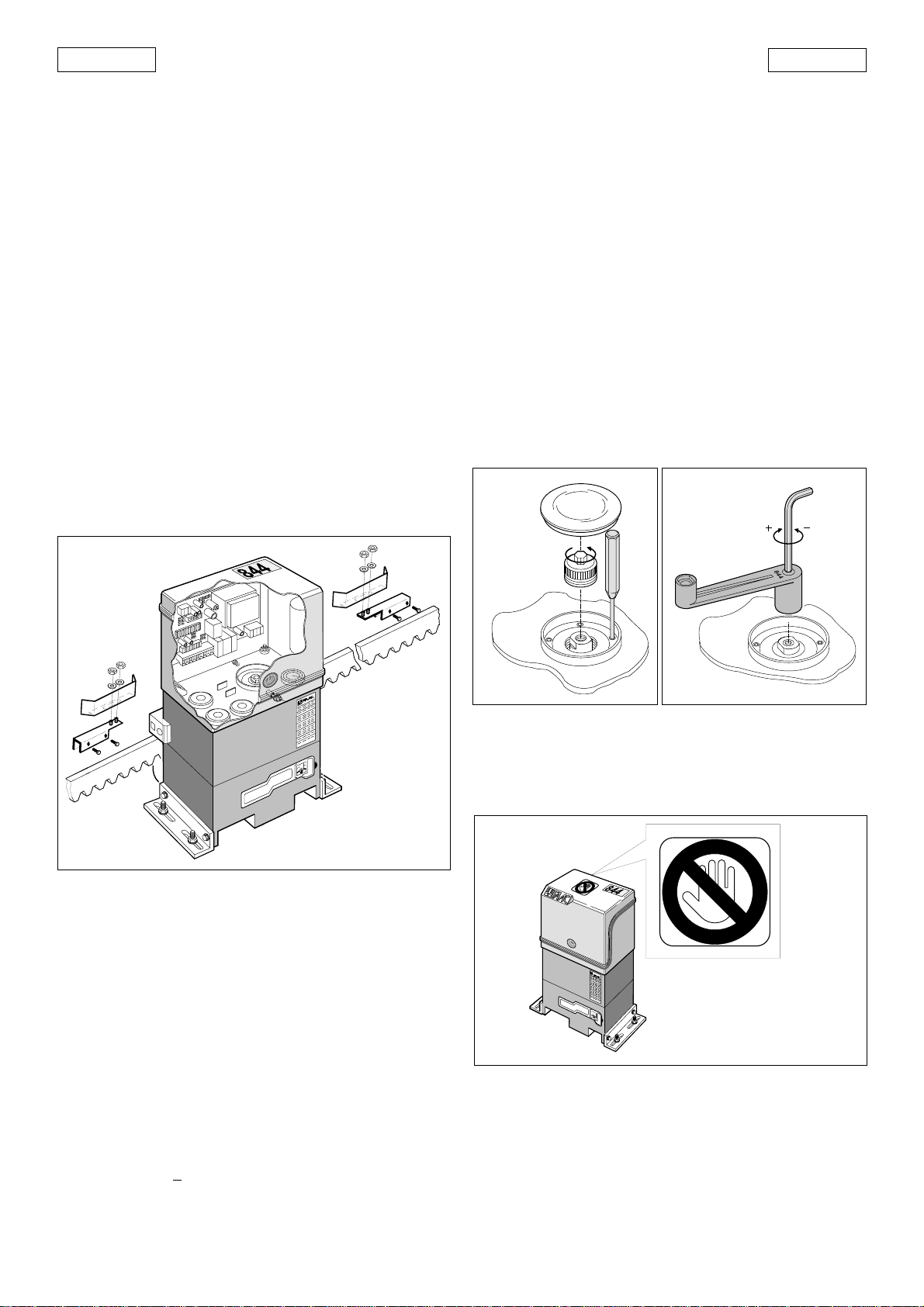
Toadjustthe thresholdoftheanti-crushingsystem, proceedas
follows:
1) Switch off the power supply.
2) Remove the cover of the relevant bore (Fig. 1- ref. 9), and
unscrew the cap of the clutch adjusting screw (Fig. 32).
3) Keepthe drivingshaft in positionby means ofthe supplied
lever, and adjust the clutch as shown in Fig. 33.
To increase torque, turn the screw clockwise.
To decrease torque, turn the screw counterclockwise.
the operator is supplied with the clutch set to maximum
torque. Initially, the working torque of the system must be
decreased.
4) Switch on the power supply and check whether the anti-
crushing system trips correctly.
Fig. 32 Fig. 33
6. TESTING THE AUTOMATION
When installation is complete, affix the danger warning label
to the top of the casing (Fig. 34).
Press fit the covers over the operator fixing bars (Fig. 35).
Thoroughly check operation of the automation and all
connected accessories.
Checktheclosurestoppositionofthegateandcheckthatthe
lock plate is in the correct position. If necessary, change its
position and recheck operation by performing a few gate
movement cycles. When you are sure that the position is
correct, fix the lock plate with screws or by welding.
alarmhasbeeneliminatedandtheRESETbuttonhasbeen
pressed (or the power supply has been momentarily inter-
rupted).
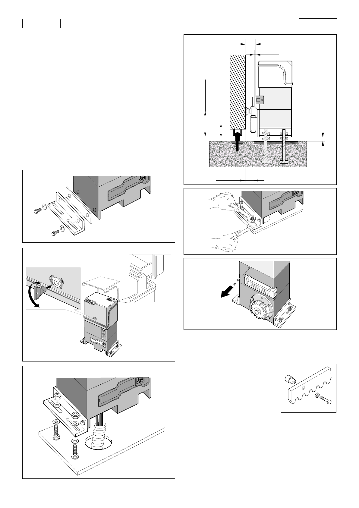
5.6. POSITIONING THE TRAVEL STOP PLATE
The 844 MC-R operator is fitted with an inductive proximity limit
switch (Fig.1 - ref.3). When the latter detects the passage of a
plate fastened to the top of the rack, it stops the movement of
the gate.
To position the two travel stop plates correctly, proceed as
follows:
1) Connect the limit switch connector to the 844MPSR con-
trol unit in accordance with the direction of gate closure
(paragraph 5.2.3. and Figs. 24/25).
2) Assemble the limit switch, positioning the stop plate cen-
trallyrelative to thethreaded studs of thebracket (Fig.31).
3) Switch on the power supply.
4) Move the gate by hand towards it closed position, stop-
ping approximately 2 cm from the physical stop of the
gate.
5) Set brake-adjusting trimmer TR1 approximately to its cen-
tral position (Fig. 19 - ref. TR1).
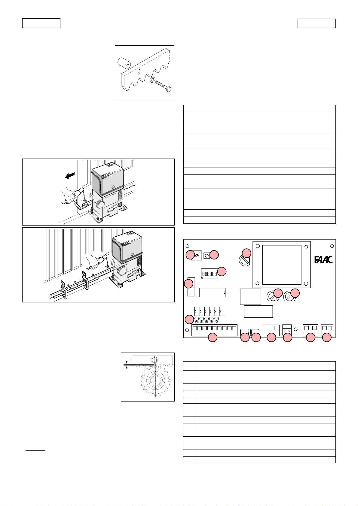
6) Slide the travel stop plate on the rack in the opening
direction. When the LED of the opening travel limit switch
(FCA)in the 844MPSR electronic control unit(Fig. 28) goes
out, advance the travel stop plate by approximately 45
mm, and fix it to the rack by tightening the screws.
7) Move the gate by hand towards its closed position, stop-
ping approximately 2 cm from the physical stop of the
gate.
8) Slide the travel stop plate on the rack in the closing direc-
tion. When the LED of the closing travel end limit switch
(FCC) in the 844 MPSR electronic control unit goes out
(Fig.28), advance the travel stop plate by approximately
45 mm, and fix it to the rack by tightening the screws.
9) Re-lock the system (see paragraph 5).
10) Run a complete cycle of the gate, to check whether the
limit switch trips correctly. To adjust the limit switch posi-
tions, operate brake trimmer TR1: when the trimmer is
rotated clockwise, the braking space is decreased; when
thetrimmerisrotatedcounterclockwise,thebrakingspace
is increased.
Notes on positioning the travel stop plates
• The distance between the limit switch and the travel stop
plate must be < 5mm (Fig.11).
• To avoid damaging the operator and/or interruptions to
service,leaveadistanceofatleast2cmfromthephysical
stops of the gate.
Fig. 31

22
ENGLISH ENGLISH
Fig. 36
Fig. 37
Fig. 38
Fig. 35
Give the customer the User Guide. Explain correct use and
operationofthegearmotoranddrawattentiontothepotential
danger zones of the automation.
7. MANUAL OPERATION
If it is necessary to operate the gate manually due to a power
failure or malfunction of the automation, release the electric
lock using the special key and move the gate leaf manually.
If this is not sufficient (serious mechanical malfunction), carry
out the following operations on the release system:
1) Openthelockcoverandinsertthekeysuppliedinthelock
(Fig.36).
2) Turn the key anti-clockwise.
3) Remove the key and close the lock cover.
4) Move the gate until the release device engages.
9. SPECIALAPPLICATIONS
There are no special applications.
10. MAINTENANCE
When performing maintenance, always check that the anti-
crushingclutchiscorrectlyadjustedandthatthesafetydevices
operate correctly.
10.1. TOPPING UP WITH OIL
Check the quantity of oil in the operator periodically.
For medium-low duty cycles an annual check is sufficient; for
more intensive use, check every 6 months.
Toaccesstheoilreservoir,removetheoilfillercap(Fig.1ref.10).
Theoillevelshouldbeuptothecopperwindingsoftheelectric
motor (Fig. 38).
To top up, pour in oil to the correct level.
Use exclusively FAAC XD 220 oil.
11. REPAIRS
For repairs contact an authorised FAAC Repair Centre.
2) Turn the key clockwise and pull out the release lever as
shown in Fig.37.
3) Open or close the gate manually.
8. RETURN TO NORMAL OPERATION
To prevent accidental operation of the gate during this
procedure, turn off the electricity supply to the system before
relocking the operator.
1) Close the release lever.

23
ENGLISH
ENGLISH
USER’S GUIDE
844 MC-R AUTOMATION
Read the instructions carefully before using the product and
keep them for future reference.
GENERAL SAFETY RULES
The 844 MC-R automation, when installed and used correctly,
affords a high level of safety.
However, some simple rules should be followed to avoid
accidents:
- Donotstandinthevicinityoftheautomationorallowanyone
else, especially children, to do so, and do not place objects
in the vicinity of the automation. This is particularly important
during operation.
- Keep remote controls or any other control devices out of the
reach of children to prevent them from accidentally operat-
ing the automation.
- Do not allow children to play with the automation.
- Do not deliberately obstruct the movement of the gate.
- Make sure that branches or bushes do not interfere with the
movement of the gate.
- Ensure that the signalling lights are efficient and clearly
visible.
- Do not attempt to move the gate manually without first
releasing it.
- In the event of a malfunction, release the gate to allow
access and call a qualified technician for service.
- If you have to use the release device to set manual opera-
tion, disconnect the electrical power supply.
- Do not make any modifications to components of the auto-
mation system.
- Donotattempttoperformanyrepairworkortamperwiththe
automation. Call FAAC qualified personnel for repairs.
- At least once every six months have the automation, the
safety devices and the earth connection checked by a
qualified technician.
DESCRIPTION
The FAAC 844 MC-R automation is ideal for controlling vehicle
access areas with medium-high transit frequencies.
The FAAC model 844 MC-R automation for sliding gates are
electromechanical operators which transmit movement to
the leaf by means of a pinion with rack or chain coupled in
appropriate manner to the sliding gate.
The operation of the sliding gate is controlled by an electronic
control unit housed inside the operator.
When the gate is closed, on receipt of an opening impulse
from a remote control or other suitable control device, the
control unit will start the motor to move the gate to the open
position.
Ifautomaticoperationhasbeenselected,sendinganimpulse
causesthe gate toreclose on its ownafter the selected pause
time.
If semiautomatic operation has been selected, a second
impulse must be sent to reclose the gate.
Anopeningimpulsesentwhile thegateisreclosing causesitto
change direction of movement.
A stop command (if available) stops movement at any time.
Fordetailed information on operationof the sliding gatein the
various operating modes, contact the installation technician.
The automations have safety devices (photocells) which
prevent the gate from reclosing when an obstacle lies within
the area they are protecting.
The system allows the gate to be moved manually when the
motor is not running, so an electric lock must be installed to
keep the gate locked when closed.
Intheeventofamalfunctionorpowerfailure,thegatecanbe
opened only by releasing the electric lock.
The gear motor has a mechanical clutch which affords the
necessary anti-crushing safety.
The electronic control unit can be incorporated into the gear
motor or installed separately.
A convenient manual release device allows the gate to be
operated in the event of a power failure or malfunction.
The light flashes while the gate is moving.
MANUAL OPERATION
If the gate has to be opened manually due to a power failure
or a malfunction of the automation, the electric lock must be
released.Ifthisisnotsufficient(seriousmechanicalmalfunction
ofthegearmotor),thefollowingoperationsmustbeperformed
on the release device.
1) Open the lock cover plate and insert the key supplied in
the lock (Fig.1).
2) Turn the key clockwise and pull the release lever as shown
in Fig. 2.
3) Open or close the gate manually.
RETURN TO NORMAL OPERATION
To prevent accidental operation of the gate during this
procedure, turn off the electricity supply to the system before
relocking the operator.
1) Reclose the release lever.
2) Turn the key anti-clockwise.
3) Remove the key and close lock cover plate.
4) Move the gate until the release device engages.
Fig. 1
Fig. 2
This manual suits for next models
1
Table of contents
Other FAAC Garage Door Opener manuals
Popular Garage Door Opener manuals by other brands

Horton
Horton Easy Access 7100 Series installation instructions

Tormatic
Tormatic W-800 manual

Like It
Like It PRO600 Instructions for fitting and operating

Seip
Seip A 45 installation instructions

Von Duprin
Von Duprin HH KAW 9847 installation instructions

Wayne-Dalton
Wayne-Dalton Torsion 7100 Series quick start guide