FAAC S800 CBAC KIT-100 User manual

S800H
Kit sblocco Idraulico - Hydraulic release kit - Kit de déverrouillage hydraulique
Bausatz Hydraulische Entriegelung - Kit desbloqueo Hidráulico
- Hydraulische ontgrendelingskit
www.metalines.com

2
KIT SBLOCCO IDRAULICO S800H
2. PROCEDURA DI INSTALLAZIONE
La presente procedura fa riferimento alla installazione del siste-
ma di sblocco idraulico sull’operatore S800H, ed è da ritenersi
una integrazione della sequenza di installazione dell’operatore,
riportata sul relativo manuale.
Le misure relative al posizionamento della cassetta devono
corrispondere con quelle riportate in Fig. 2.
Sbloccare l’automazione
Posizionare i componenti del kit giunto scanalato come
indicato in Fig. 3 e Fig. 4, curando di rispettare il posiziona-
mento del riferimento sul giunto scanalato; saldare il profilo
ad U al giunto scanalato come illustrato in Fig. 4
Procedere con la installazione secondo quanto riportato
nelle istruzioni dell’operatore S800H, in particolare per quan-
to riguarda il posizionamento dello stesso internamente
alla cassetta
Installato l’operatore, fissare il sistema di sblocco tramite le
due viti M8 in dotazione (fig. 5 rif.
a)
•
•
•
•
La descrizione dei componenti dello sblocco è riferita alla
Fig.1
a Viti di fissaggio del sistema di sblocco
b Viti di spurgo
c Serratura di sblocco (a/b)
d Copertura viti di spurgo
e Viti di fissaggio raccordo
f Guarnizioni di tenuta
g Tubo di collegamento
h Raccordo
i Recipiente olio
jDima di foratura
1. DESCRIZIONE DEI COMPONENTI
Nel caso si stia installando lo sblocco su un sistema già
esistente, equipaggiato con cassetta pre-modifica, i fori
di fissaggio potrebbero non essere presenti.
In tal caso occorre fare riferimento alla dima inclusa
con il sistema di sblocco e predisporre autonomamente
i due fori filettati M8 necessari al fissaggio (rif. cap. 4).
Rimuovere i raccordi di spurgo installati sull’operatore e
successivamente collegare quelli forniti con il sistema di
sblocco (Fig. 5 rif.
b e Fig. 1 rif. da e a h)
Bloccare nuovamente l’operatore.
•
•
La presenza d’aria nel circuito idraulico provoca un irregolare
funzionamento dell’automazione, che si manifesta con un
anomalo movimento dell’anta ed un eccessivo rumore durante
l’esercizio.
Per ovviare al problema è necessario agire come segue:
1) Comandare l’apertura del cancello.
2) Durante il movimento dell’anta, allentare la vite di spurgo
d’apertura (Fig.6 rif.a)
3. SPURGO DELL’AUTOMAZIONE
3) Fare fuoriuscire l’aria, tramite la vite di spurgo, dal circuito
idraulico fino alla comparsa di olio non emulsionato.
4) Serrare la vite di spurgo prima che l’operatore termini il ciclo
d’apertura.
5) Comandare la chiusura del cancello.
6) Durante il movimento dell’anta, allentare la vite di spurgo
di chiusura (Fig.6 rif.b )
7) Fare fuoriuscire l’aria, tramite la vite di spurgo, dal circuito
idraulico fino alla comparsa di olio non emulsionato.
8) Serrare la vite di spurgo prima che l’operatore termini il ciclo
di chiusura.
9) Ripetere le operazioni se necessario.
10) Ripristinare il livello dell’olio, utilizzando quello fornito nel kit,
in modo che esso si trovi appena sotto il tappo (Fig. 7 rif.a).
4. USO DELLA DIMA DI FORATURA
L’uso della dima di foratura si rende necessario qualora si
proceda ad applicare il sistema di sblocco idraulico su di una
automazione già installata, rimuovendo il sistema di sblocco
meccanico precedentemente esistente.
In tal caso, sulla cassetta portante saranno assenti i due fori di
fissaggio del sistema di sblocco idraulico.
Rimuovere il vecchio sistema di sblocco
Installare il nuovo kit giunto scanalato (fare riferimento al
capitolo 2 a tale proposito)
Piegare la dima lungo il riferimento premarcato (Fig.9 rif.
a)
Facendo coincidere il profilo curvo della dima con il kit
giunto (Fig.9 rif.b), segnare la posizione dei due fori sulla
cassetta (Fig.9 rif.c).
Effettuare i prefori diametro Ø 6,5mm (Fig.9 rif.d)
Filettare i prefori con maschio M8 (Fig.9 rif.e)
•
•
•
•
•
•
5. USO DEL SISTEMA DI SBLOCCO
Per sbloccare l’operatore, rimuovere la protezione plastica,
inserire la chiave e ruotare la serratura di sblocco di circa un
giro in senso antiorario. (Fig. 8 rif. a)
Per bloccare nuovamente l’operatore, ruotare la serratura di
sblocco in senso orario fino a battuta, senza forzare ulterior-
mente (Fig. 8 rif. b)
ITALIANO
ATTENZIONE! Proteggere adeguatamente l’ope-
ratore durante la fase di foratura per evitare di
danneggiarlo, oppure rimuoverlo dalla cassetta.
In caso di rimozione, fare riferimento alle istruzioni
per rimettere in fase anta e operatore al momento
del montaggio.
Le presenti istruzioni sono valide per i seguenti modelli:
S700H – S800H
www.metalines.com

3
ENGLISH
S800H HYDRAULIC RELEASE KIT
2. INSTALLATION PROCEDURE
This operation refers to the installation of the hydraulic release
system on the S800H operator and it must be considered as an
additional procedure of the operator installation sequence
indicated on the manual.
The dimensions concerning the box position must correspond
to those given in Fig. 2.
Release the automated system
Place the components of the grooved coupling kit as shown
in Fig. 3 and Fig. 4, taking care to observe the position of
the reference on the grooved coupling; weld the U-shaped
profile to the grooved coupling as shown in Fig. 4
Continue installation according to the instructions of the
S800H operator, especially as far as its position in the box
is concerned
After having installed the operator, fasten the release
system using the two supplied M8 screws (fig. 5 ref.
a)
•
•
•
•
The description of the release components refers to Fig.1
a Fastening screws for the release system
b Bleed screws
c Release lock (a/b)
d Bleed screws cover
e Union fastening screws
f Sealing gaskets
g Connection tube
h Union
i Oil tank
jDrilling template
1. DESCRIPTION OF COMPONENTS
If you are installing the release device on an already
existing system, equipped with a pre-modification box,
the fastening holes could be absent.
In such a case, refer to the template supplied with
the release system and drill two M8 threaded holes
necessary for the fastening operation (ref. chapt. 4).
Remove the bleed unions on the operator, then connect
those supplied with the release system (Fig. 5 ref.
b
and
Fig. 1 ref. from e to h)
Lock the operator again.
•
•
Air in the hydraulic circuit causes irregular operation of the
automated system that shows up with an incorrect movement
of the leaf and excessive noise during operation.
To solve this problem, operate as follows:
1) Command an opening movement of the gate.
2) During the leaf movement, loosen the opening bleed screw
(Fig.6 ref.a)
3. BLEEDING THE AUTOMATED SYSTEM
3) Let air come out from the hydraulic circuit through the bleed
screw until non-emulsified oil comes out.
4) Tighten the bleed screw before the operator ends the
opening cycle.
5) Command a closing movement of the gate.
6) During the leaf movement, loosen the closing bleed screw
(Fig.6 ref. b)
7) Let air come out from the hydraulic circuit through the bleed
screw until non-emulsified oil comes out.
8) Tighten the bleed screw before the operator ends the closing
cycle.
9) Repeat the operations, if necessary.
10) Restore the oil level until it is just under the cap, using oil
supplied with the kit (Fig. 7 ref.a).
4. USING THE DRILLING TEMPLATE
You need to use the drilling template whenever you need to
fit the hydraulic release kit to an already existing automated
system, removing thus the previous mechanical release
system.
In such a case, the carrying box has no fastening holes for the
hydraulic release system.
Remove the old release system
Install the new grooved coupling kit (refer to chapter 2)
Fold the template along the pre-marked reference (Fig.9
ref. a)
Match the curved profile of the template with the coupling
kit (Fig.9 ref.b), mark the position of the two holes on the
box (Fig.9 ref.c).
Drill pre-holes, diameter Ø 6.5mm (Fig.9 ref. d)
Thread the pre-holes with a tap M8 (Fig.9 ref.e)
•
•
•
•
•
•
5. USING THE RELEASE SYSTEM
To release the operator, remove the plastic cover, insert the
key and turn the release lock counter-clockwise for about one
turn. (Fig. 8 ref. a)
To lock the operator again, turn the release lock clockwise until
reaching the stop point, do not force (Fig. 8 ref. b)
IMPORTANT! Protect the operator in a suitable
way during the drilling operation in order not to
damage it, otherwise remove it from the box.
Ifyouremoveit,refertotheinstructiontosynchronise
leaf and operator during the assembly.
These instructions apply to the following models:
S700H – S800H
www.metalines.com

4
FRANÇAIS
KIT DE DÉVERROUILLAGE HYDRAULIQUE S800H
2. PROCÉDURE D’INSTALLATION
La présente procédure se réfère à l’installation du système de
déverrouillage hydraulique sur l’opérateur S800H ; il s’agit d’une
intégration de la séquence d’installation de l’opérateur, figurant
dans le manuel correspondant.
Les dimensions relatives au positionnement du boîtier doivent
correspondre à celles de la Fig. 2.
Déverrouiller l’automatisme.
Positionner les éléments du kit joint rainuré d’après la
Fig. 3 et la Fig. 4, en respectant le positionnement de la
référence sur le joint rainuré ; souder le profil en U sur ce
dernier d’après la Fig. 4
Procéder à l’installation en suivant les instructions de
l’opérateur S800H, en particulier pour ce qui concerne le
positionnement de ce dernier à l’intérieur du boîtier
Après avoir installé l’opérateur, fixer le système de
déverrouillage avec les deux vis M8 fournies (fig. 5 réf.
a)
•
•
•
•
La description des composants du système de déverrouillage
se réfère à la Fig.1
a Vis de fixation du système de déverrouillage
bVis de purge
cSerrure de déverrouillage (a/b)
dCache-vis de purge
eVis de fixation du raccord
fJoints d’étanchéité
gTube de connexion
h Raccord
iRécipient d’huile
j Gabarit de perçage
1. DESCRIPTION DES COMPOSANTS
En cas d’installation du dispositif de déverrouillage sur
un système existant, muni d’un boîtier pré-modification,
les trous de fixation pourraient être absents.
Dans ce cas, se référer au gabarit fourni avec le système
de déverrouillage et disposer de manière autonome
les deux trous taraudés M8 nécessaires pour la fixation
(réf. chap. 4).
Démonter les raccords de purge installés sur l’opérateur
puis connecter les raccords fournis avec le système de
déverrouillage (Fig. 5 réf.
b
et Fig. 1 réf. de
e
à
h
)
Bloquer de nouveau l’opérateur
.
•
•
La présence d’air dans le circuit hydraulique provoque un
fonctionnement irrégulier de l’automatisme ; celui-ci se
manifeste par un mouvement anormal du vantail et un bruit
excessif durant le fonctionnement.
Pour remédier au problème, procéder comme suit :
1) Commander l’ouverture du portail.
2) Durant le mouvement du vantail, desserrer la vis de purge
d’ouverture (Fig.6 réf. a)
3. PURGE DE L’AUTOMATISME
3) Laisser s’échapper à travers la vis de purge l’air en
provenance du circuit hydraulique jusqu’à la présence de
l’huile émulsionnée.
4) Serrer la vis de purge avant que l’opérateur ne termine le
cycle d’ouverture.
5) Commander la fermeture du portail.
6) Durant le mouvement du vantail, desserrer la vis de purge
de fermeture (Fig.6 réf.b)
7) Laisser s’échapper à travers la vis de purge l’air en
provenance du circuit hydraulique jusqu’à la présence de
l’huile émulsionnée.
8) Serrer la vis de purge avant que l’opérateur ne termine le
cycle de fermeture.
9) Répéter les opérations en cas de besoin.
10) Rétablir le niveau d’huile, en utilisant l’huile fournie, de
manière à ce que le niveau se situe immédiatement sous le
bouchon (Fig.7 réf.a).
4. UTILISATION DU GABARIT DE PERÇAGE
L’utilisation du gabarit de perçage est nécessaire si l’on
applique le système de déverrouillage hydraulique sur un
automatisme existant, impliquant le démontage du système
de déverrouillage mécanique présent.
Dans ce cas, le boîtier porteur est dépourvu des deux trous de
fixation du système de déverrouillage hydraulique.
Démonter le système de déverrouillage existant.
Installer le nouveau kit joint rainuré (voir le chapitre 2 à ce
propos).
Plier le gabarit le long de la référence prémarquée (Fig.9
réf. a)
Faire coïncider le profil courbe du gabarit et le kit joint (Fig.9
réf. b), marquer la position des deux trous sur le boîtier
(Fig.9 réf. c).
Réaliser les pré-trous diamètre Ø 6,5mm (Fig.9 réf. d)
Tarauder les pré-trous à l’aide d’un foret mâle M8 (Fig.9
réf.e)
•
•
•
•
•
•
5. UTILISATION DU SYSTÈME DE DÉVERROUILLAGE
Pour déverrouiller l’opérateur, enlever la protection en plastique,
introduire la clé et tourner la serrure de déverrouillage d’environ
un tour en sens inverse horaire. (Fig. 8 réf. a)
Pour bloquer de nouveau l’opérateur, tourner la serrure de
déverrouillage en sens horaire jusqu’à la butée, sans forcer
davantage (Fig. 8 réf. b)
ATTENTION ! Protéger correctement l’opérateur
durant la phase de perçage pour éviter de
l’endommager ou l’extraire du boîtier.
En cas d’extraction du boîtier, consulter les
instructions pour remettre le vantail et l’opérateur
en phase au moment du montage.
Les instructions suivantes s’appliquent aux modèles sui-
vants : S700H – S800H
www.metalines.com

5
DEUTSCH
BAUSATZ HYDRAULISCHE ENTRIEGELUNG S800H
2. MONTAGEANWEISUNGEN
Diese Anweisungen gelten für die Montage des hydraulischen
Entriegelungssystems am Antrieb S800H und dienen als
Ergänzung für die Anleitungen zur Montage des Antriebs, die
im entsprechenden Handbuch enthalten sind.
Die Maße für die Positionierung des Kastens müssen den Werten
in Abb. 2 entsprechen.
Die Automation entriegeln
Die Komponenten des Bausatzes genutete Verbindung
gemäß den Angaben in Abb. 3 und Abb. 4 positionieren
und dabei auf die Markierung an der genuteten Verbindung
achten. Das U-Profil an der genuteten Verbindung
verschweißen (siehe Abb. 4).
Die Montage gemäß den Angaben in den Anweisungen
für den Antrieb S800H vornehmen und dabei besonders
dessen Position im Kasten beachten.
Den Antrieb montieren und das Entriegelungssystem mithilfe
der zwei im Lieferumfang enthaltenen Schrauben M8
fixieren (Abb. 5, Bez.
a)
•
•
•
•
Die Beschreibung der Entriegelungsbauteile bezieht sich auf
die Abb. 1
a Befestigungsschrauben des Entriegelungssystems
bEntlüftungsschrauben
c Entriegelungsschloss (a/b)
dAbdeckung Entlüftungsschrauben
eBefestigungsschrauben Verbindungsstück
f Dichtungen
g Anschlussrohr
h Verbindungsstück
i Ölbehälter
j Bohrschablone
1. BESCHREIBUNG DER BAUTEILE
Wenn die Entriegelung an einem bereits bestehenden
System montiert wird, das mit einem Kasten vor der
Änderung ausgerüstet ist, muss damit gerechnet werden,
dass die Befestigungsöffnungen nicht vorhanden sind.
IndiesemFalldieimLieferumfangdesEntriegelungssystems
enthaltene Bohrschablone verwenden und die zwei für
die Befestigung erforderlichen Gewindebohrungen M8
bohren (Bez. Kap. 4).
Die am Antrieb montierten Entlüftungsverbindungen
entfernenundanschließenddiemitdemEntriegelungssystem
gelieferten anschließen (Abb. 5, Bez.
b
und Abb. 1, Bez.
von
a
bis
h
).
Den Antrieb erneut verriegeln.
•
•
Luft im Hydrauliksystem verursacht Betriebsstörungen der
Automation, die unregelmäßige Flügelbewegungen und
übermäßigen Betriebslärm zur Folge haben.
Um Abhilfe zu schaffen, sind folgende Schritte auszuführen:
1) Einen Befehl für die Öffnung des Tors senden.
2) Während der Flügelbewegung die Entlüftungsschraube beim
Öffnen lockern (Abb. 6, Bez. a).
3. ENTLÜFTEN DER AUTOMATION
3) Über die Entlüftungsschraube solange Luft aus dem
Hydrauliksystem ablassen, bis nicht emulgiertes Öl austritt.
4) Die Entlüftungsschraube festziehen, bevor der Antrieb den
Öffnungsvorgang abgeschlossen hat.
5) Einen Befehl zum Schließen des Tors senden.
6) Während der Flügelbewegung die Entlüftungsschraube beim
Schließen lockern (Abb. 6, Bez. b).
7) Über die Entlüftungsschraube solange Luft aus dem
Hydrauliksystem ablassen, bis nicht emulgiertes Öl austritt.
8) Die Entlüftungsschraube festziehen, bevor der Antrieb den
Schließvorgang abgeschlossen hat.
9) Die Vorgänge gegebenenfalls wiederholen.
10) Öl nachfüllen (das im Lieferumfang des Bausatzes enthaltene
Öl verwenden) – Füllstand knapp unter dem Stopfen (Abb. 7,
Bez.a).
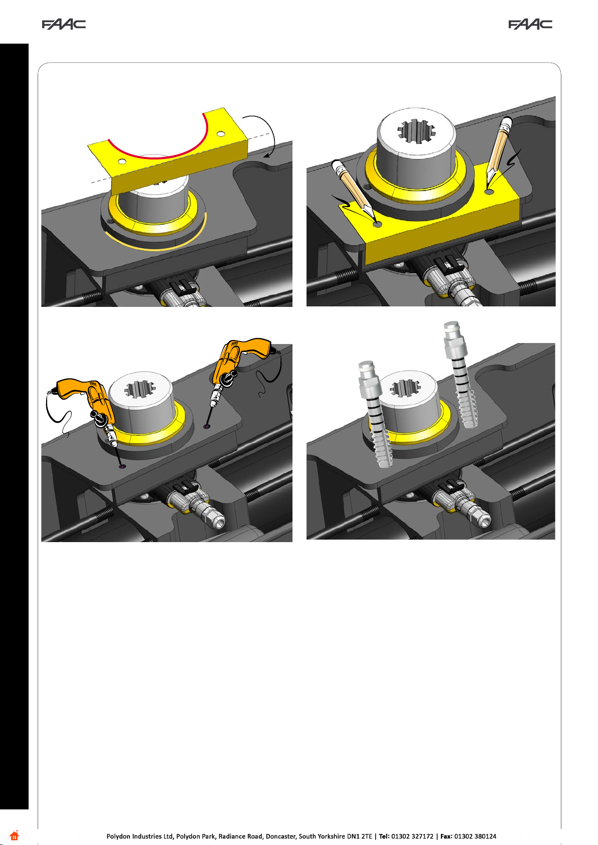
4. VERWENDUNG DER BOHRSCHABLONE
Die Bohrschablone muss verwendet werden, wenn das
hydraulische Entriegelungssystem an einer bereits montierten
Automation angebracht wird. Dafür ist das zuvor bestehende
mechanische Entriegelungssystem zu entfernen.
In diesem Fall weist der Kasten keine Befestigungsöffnungen für
das hydraulische Entriegelungssystem auf.
Das alte Entriegelungssystem entfernen
Den neuen Bausatz genutete Verbindung montieren (siehe
Kapitel 2)
Die Schablone an der Markierung umbiegen (Abb. 9,
Bez. a)
Das gekrümmte Profil der Schablone auf den
Verbindungsbausatz auflegen (Abb. 9, Bez. b), und die
Position der zwei Bohrungen am Kasten markieren (Abb.
9, Bez. c)
Die Vorbohrungen mit Durchmesser 6,5 mm ausführen
(Abb. 9, Bez. d)
Die Vorbohrungen mit dem Gewindebohrer M8 bohren
(Abb. 9, Bez.e)
•
•
•
•
•
•
5. VERWENDUNG DES ENTRIEGELUNGSSYSTEMS
Zum Entriegeln des Antriebs die Kunststoffabdeckung abnehmen,
den Schlüssel einstecken und das Entriegelungsschloss gegen
den Uhrzeigersinn ungefähr einmal vollständig drehen. (Abb. 8
Bez. a)
Zum erneuten Verriegeln des Antriebs das Entriegelungsschloss
im Uhrzeigersinn bis zum Anschlag drehen und dabei keine
Gewalt anwenden (Abb. 8, Bez. b)
ACHTUNG! Damit der Antrieb nicht beschädigt
wird, muss er entweder während des Bohrens
angemessen geschützt oder vom Kasten entfernt
werden.
Bei der erneuten Montage eines entfernten
Antriebs die Anweisungen zur Anpassung von
Flügel und Antrieb beachten.
Die vorliegenden Anleitungen sind für die folgenden
Modelle gültig: S700H – S800H.
www.metalines.com

6
ESPAÑOL
KIT DESBLOQUEO HIDRÁULICO S800H
2. PROCEDIMIENTO DE INSTALACIÓN
Las presentes instrucciones describen la instalación del sistema
de desbloqueo hidráulico en el operador S800H, y deben
considerarse una integración de las instrucciones para la
instalación del operador incluidas en el correspondiente
manual.
Las medidas para la colocación de la caja deben coincidir
con las indicadas en la Fig. 2.
Desbloquee el automatismo.
Coloque los componentes del kit junta acanalada como
se indica en la Fig. 3 y en la Fig. 4, prestando atención a
respetar el posicionamiento de la referencia situada en la
junta acanalada. Suelde el perfil en U a la junta acanalada
como se muestra en la Fig. 4.
Proceda con la instalación siguiendo las instrucciones
del operador S800H, y en especial la parte dedicada al
posicionamiento del mismo dentro de la caja.
Una vez instalado el operador, fije el sistema de desbloqueo
con los dos tornillos M8 suministrados en dotación (fig. 5
ref.
a)
•
•
•
•
La descripción de los componentes del desbloqueo hace
referencia a la Fig.1
a Tornillos de fijación del sistema de desbloqueo
b Tornillos de purga
c Cerradura de desbloqueo (a/b)
d Tapa de los tornillos de purga
e Tornillos de fijación racor
f Juntas de estanqueidad
g Tubo de conexión
h Racor
i Recipiente de aceite
jPlantilla de taladrado
1. DESCRIPCIÓN DE LOS COMPONENTES
Si se instala el desbloqueo en un sistema ya existente,
equipado con caja previa a la modificación, los orificios
de fijación podrían no estar presentes.
En este caso debe utilizarse la plantilla suministrada con
el sistema de desbloqueo y efectuar los dos orificios
roscados M8 necesarios para la fijación (ref. cap. 4).
Retire los racores de purga instalados en el operador y
seguidamente conecte los racores suministrados con el
sistema de desbloqueo (Fig. 5 ref. by Fig. 1 ref. de ea h)
Bloquee de nuevo el operador.
•
•
La presencia de aire en el circuito hidráulico ocasiona un
funcionamiento irregular del automatismo, que se manifiesta
con un movimiento anómalo de la hoja y un excesivo ruido
durante el funcionamiento.
Para obviar el problema proceda del siguiente modo:
1) Mande la apertura de la cancela.
2) Durante el movimiento de la hoja, afloje el tornillo de purga
de apertura (Fig.6 ref.a)
3. PURGADO DEL AUTOMATISMO
3) Por medio del tornillo de purga haga salir el aire del circuito
hidráulico, hasta que salga aceite no emulsionado.
4) Apriete el tornillo de purga antes de que el operador termine
el ciclo de apertura.
5) Mande el cierre de la cancela.
6) Durante el movimiento de la hoja, afloje el tornillo de purga
de cierre (Fig.6 ref.b).
7) Por medio del tornillo de purga haga salir el aire del circuito
hidráulico, hasta que salga aceite no emulsionado.
8) Apriete el tornillo de purga antes de que el operador termine
el ciclo de cierre.
9) Repita las operaciones si fuera necesario.
10) Reponga el nivel de aceite, utilizando el suministrado en
el kit, de modo que el mismo esté justo por debajo del tapón
(Fig. 7 ref.a).
4. USO DE LA PLANTILLA DE TALADRADO
Es necesario usar la plantilla de taladrado cuando se procede a
aplicar el sistema de desbloqueo hidráulico en un automatismo
ya instalado, retirando el sistema de desbloqueo mecánico
existente.
En dicho caso, en la caja portante no estarán presentes los dos
orificios de fijación del sistema de desbloqueo hidráulico.
Retire el viejo sistema de desbloqueo.
Instale el nuevo kit junta acanalada (consultar el capítulo 2).
Doble la plantilla a lo largo de la referencia premarcada
(Fig.9 ref. a).
Haga coincidir el perfil curvado de la plantilla con el kit
junta (Fig.9 ref.b), y marque la posición de los dos orificios
en la caja (Fig.9 ref.c).
Realice los pretaladrados de diámetro Ø 6,5mm (Fig.9
ref. d).
Rosque los pretaladrados con un macho M8 (Fig.9 ref.e)
•
•
•
•
•
•
5. USO DEL SISTEMA DE DESBLOQUEO
Para desbloquear el operador retire la protección de plástico,
introduzca la llave y gire aproximadamente una vuelta
en sentido antihorario la cerradura de desbloqueo. (Fig. 8
ref. a).
Para volver a bloquear el operador gire la cerradura de
desbloqueo en sentido horario hasta el tope, sin forzarla (Fig. 8
ref. b)
¡ATENCIÓN! Proteja adecuadamente el operador
durante la fase de taladrado para impedir que se
dañe, o bien retírelo de la caja.
Si opta por retirarlo, consulte las instrucciones
para volver a poner en fase la hoja y el operador
durante el montaje.
Las presentes instrucciones son válidas para los siguientes
modelos: S700H – S800H
www.metalines.com

7
NEDERLANDS
HYDRAULISCHE ONTGRENDELINGSKIT S800H
2. INSTALLATIEPROCEDURE
Deze procedure betreft de installatie van het hydraulische
ontgrendelingssysteem op de aandrijving S800H, en vormt een
aanvulling op de installatieprocedure van de aandrijving die is
aangegeven in de bijbehorende handleiding.
De afmetingen voor het plaatsen van de behuizing moeten
overeenkomen met die in Fig.2.
Automatisch systeem ontgrendelen
Plaats de onderdelen van de kit met groefverbinding zoals
aangegeven in Fig.3 en Fig.4 met inachtneming van de
markering op de groefverbinding; las het U-profiel aan de
groefverbinding zoals geïllustreerd in Fig.4
Vervolg de installatie volgens de instructies van de
aandrijving S800H, met name die over hoe zij in de
behuizing moet worden geplaatst.
Installeerdeaandrijving,bevestighetontgrendelingssysteem
met de twee bijgeleverde schroeven M8 (fig.5 ref.
a).
•
•
•
•
De beschrijving van de onderdelen van de ontgrendeling
betreft Fig.1
a Bevestigingsschroeven van het ontgrendelingssysteem
b Ontluchtingsplug
c Slot ontgrendeling (a/b)
d Dop ontluchtingsplug
e Bevestigingsschroeven aansluiting
f Dichting
g Verbindingsleiding
h Aansluiting
i Oliereservoir
jSjabloon voor het boren
1. BESCHRIJVING VAN DE ONDERDELEN
Als een ontgrendeling wordt geïnstalleerd op een reeds
bestaand systeem met van een behuizing van voor de
wijziging, kan het zijn dat er geen bevestigingsgaten
in zitten.
Gebruik in dat geval de sjabloon die bij het
ontgrendelingssysteem is geleverd, en boor zelf de
twee gaten met schroefdraad M8 die nodig zijn voor
de bevestiging (zie hst. 4).
Verwijder de ontluchtingsaansluitingen die op de aandrijving
zijn geïnstalleerd, en sluit de bij het ontgrendelingssysteem
geleverde aan (Fig.5 ref.
b
en Fig.1 ref.
e
tot
h
)
Vergrendel de aandrijving weer
.
•
•
Als er lucht in het hydraulische circuit zit, werkt het automatisch
systeem niet goed, met als gevolg dat de vleugel schokkerig
beweegt en veel lawaai maakt tijdens de werking.
Handel als volgt om dit probleem te verhelpen:
1) Geef het commando voor het openen van de poort.
2) Draai terwijl de vleugel in beweging is de ontluchtingsplug
voor het openen los (Fig.6 ref.a)
3. ONTLUCHTING VAN HET AUTOMATISCH SYSTEEM
3) Laat de lucht via de ontluchtingsplug uit het hydraulische
circuit ontsnappen tot er niet-geëmulgeerde olie verschijnt.
4) Draai de ontluchtingsplug vast voordat de aandrijving de
openingscyclus heeft beëindigd.
5) Geef het commando voor het sluiten van de poort.
6) Draai terwijl de vleugel in beweging is de ontluchtingsplug
voor het sluiten los (Fig.6 ref.b)
7) Laat de lucht via de ontluchtingsplug uit het hydraulische
circuit ontsnappen tot er niet-geëmulgeerde olie verschijnt.
8) Draai de ontluchtingsplug vast voordat de aandrijving de
sluitingscyclus heeft beëindigd.
9) Herhaal deze handeling indien nodig.
10) Herstel het oliepeil door de bij de kit verstrekte olie bij te
vullen tot het peil vlak onder de dop komt (Fig.7 ref.a).
4. GEBRUIK SJABLOON VOOR HET BOREN
De sjabloon voor het boren moet worden gebruikt als de
hydraulische ontgrendeling wordt gemonteerd op een reeds
geïnstalleerd automatisch systeem, waarbij het bestaande
mechanische ontgrendelingssysteem wordt verwijderd.
In dat geval heeft de behuizing geen bevestigingsgaten voor
het hydraulische ontgrendelingssysteem.
Verwijder het oude ontgrendelingssysteem
Installeer de nieuwe kit met groefverbinding (zie hoofdstuk
2)
Buig de sjabloon langs de aangegeven markering (Fig.9
ref.a)
Zorg dat het gebogen profiel van de sjabloon samenvalt
met de verbindingskit (Fig.9 ref.b), en markeer de positie
van de twee gaten op de behuizing (Fig.9 ref.c)
Boor de gaten met diameter Ø 6,5mm (Fig.9 ref.d)
Schroef de bouten M8 in de gaten (Fig.9 ref.e)
•
•
•
•
•
•
5. GEBRUIK VAN DE ONTGRENDELINGSSYSTEEM
Om de aandrijving te ontgrendelen moet de kunststof
bescherming worden verwijderd, steek dan de sleutel in het
slot en draai hem ongeveer een slag tegen de wijzers van de
klok in. (Fig.8 ref.a).
Om de aandrijving weer te vergrendelen moet de sleutel met
de wijzers van de klok mee worden gedraaid tot hij niet verder
kan, zonder hem te forceren (Fig.8 ref. b)
LET OP! Bescherm de aandrijving tijdens het boren
om te voorkomen dat zij beschadigd raakt, of
verwijder haar uit de behuizing.
Als zij wordt verwijderd, raadpleeg dan de
instructies om de vleugel en de aandrijving bij het
monteren te synchroniseren.
Deze aanwijzingen gelden voor de volgende modellen:
S700H – S800H
www.metalines.com

a
bc ac b
d
Fig. 1
e
f
g
h
Fig. 2
57
A
A = 45 mm
==
Fig. 3 Fig. 4
Raccolta immagini - Pictures collection - Collection de Figures -
Conjunto de imágenes - Abbildungen - Fotoverzameling
NEDERLANDS ESPAÑOL DEUTSCH FRANÇAIS ENGLISH ITALIANO
i
j
www.metalines.com

Fig. 5
b
a
Fig. 6
a
b
a
Fig. 7
Fig. 8
a
b
NEDERLANDS ESPAÑOL DEUTSCH FRANÇAIS ENGLISH ITALIANO
www.metalines.com

a
b
c
dØ 6,5mm eM8
Fig. 9
NEDERLANDS ESPAÑOL DEUTSCH FRANÇAIS ENGLISH ITALIANO
www.metalines.com

FAAC S.p.A.
Via Calari, 10
40069 Zola Predosa (BO) - ITALIA
Tel. 0039.051.61724 - Fax. 0039.051.758518
www.faac.it
www.faacgroup.com
732957 - Rev. B
Le descrizioni e le illustrazioni del presente manuale non sono impegnative. La FAAC si riserva il diritto, lasciando inal-
terate le caratteristiche essenziali dell’apparecchiatura, di apportare in qualunque momento e senza impegnarsi
ad aggiornare la presente pubblicazione, le modifiche che essa ritiene convenienti per miglioramenti tecnici o per
qualsiasi altra esigenza di carattere costruttivo o commerciale.
The descriptions and illustrations contained in the present manual are not binding. FAAC reserves the right, whilst
leaving the main features of the equipments unaltered, to undertake any modifications it holds necessary for either
technical or commercial reasons, at any time and without revising the present publication.
Les descriptions et les illustrations du présent manuel sont fournies à titre indicatif. FAAC se réserve le droit d’apporter à
tout moment les modifications qu’elle jugera utiles sur ce produit tout en conservant les caractéristiques essentielles,
sans devoir pour autant mettre à jour cette publication.
Die Beschreibungen und Abbildungen in vorliegendem Handbuch sind unverbindlich. FAAC behält sich das Recht
vor, ohne die wesentlichen Eigenschaften dieses Gerätes zu verändern und ohne Verbindlichkeiten in Bezug auf die
Neufassung der vorliegenden Anleitungen, technisch bzw. konstruktiv/kommerziell bedingte Verbesserungen vorzu-
nehmen.
Las descripciones y las ilustraciones de este manual no comportan compromiso alguno. FAAC se reserva el derecho,
dejando inmutadas las características esenciales de los aparatos, de aportar, en cualquier momento y sin compro-
meterse a poner al día la presente publicación, todas las modificaciones que considere oportunas para el perfec-
cionamiento técnico o para cualquier otro tipo de exigencia de carácter constructivo o comercial.
De beschrijvingen in deze handleiding zijn niet bindend. FAAC behoudt zich het recht voor op elk willekeurig momentde
veranderingen aan te brengen die het bedrijf nuttig acht met het oog op technische verbeteringen of alle mogelijke
andere productie- of commerciële eisen, waarbij de fundamentele eigenschappen van de apparaat gehandhaafd
blijven, zonder zich daardoor te verplichten deze publicatie bij te werken.
www.metalines.com
Table of contents
Languages:
Other FAAC Garage Door Opener manuals
Popular Garage Door Opener manuals by other brands

Chamberlain
Chamberlain 1280 - 1/2 HP owner's manual

Fac
Fac MULTITELESCOPIC Assembly instructions

Chamberlain
Chamberlain Whisper Drive Security+ WD952KD owner's manual

Aprimatic
Aprimatic GA-MATIC BASIC CF800 Mechanical installation, Use and Maintenance instructions

Teckentrup
Teckentrup CarTeck 12.1 Installation and operating instructions

CAME
CAME VER Series installation manual