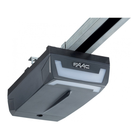
FAAC D064 User manual

D064

2
These instructions apply to model FAAC D064.
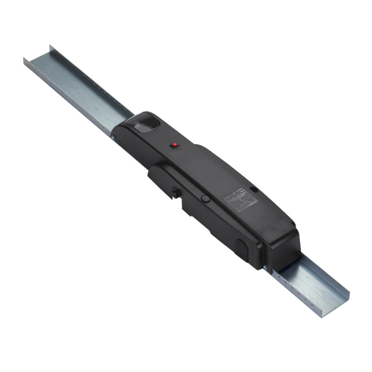
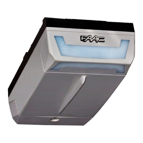
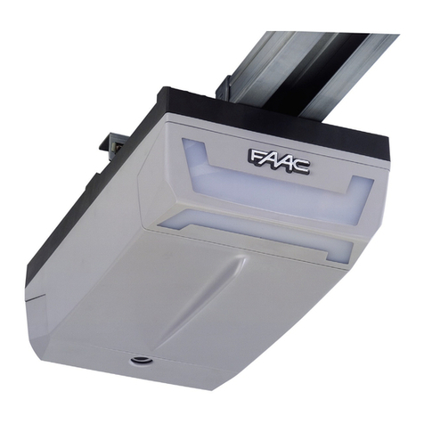
The D064 automated systems make it possible to automate
balanced sectional doors of single garages for residential
use.
They consist of an electro-mechanical operator, electronic
control unit and courtesy light built into a single unit. This unit is
fitted to the ceiling and opens the door by means of a transmission
chain or belt.
The system is non-reversing and, therefore, the door locks
mechanically when the motor is not operating and, consequently,
no lock is necessary; two manual releases, one on the inside
and one on the outside (optional) make it possible to move the
door in case of a power cut or fault.
The operator is supplied with an electronic device that detects
the presence of an obstacle that would hinder door movement
- the device prevents crushing or lifting.
This instruction refers to the operator with chain drive, but the
same procedures, regulations and application limits apply also
to the belt driven operator.
The D064 automated systems were designed and built for
indoor use and to control vehicle access. Do not use them for
any other purpose.
AUTOMATED SYSTEM D064
1 PRELIMINARY CHECKS
- The structure of the door must be suitable for fitting automation.
In particular, check that the door dimensions conform to
those indicated in the technical specifications, and that it is
sufficiently sturdy.
- Check if the door conforms to standards EN12604 and
EN12605.
- As it moves, the door must not encroach public areas
dedicated to pedestrian or vehicular transport.
- Check the efficiency of the door bearings and joints.
- Make sure that the door is friction-free. If necessary clean
and lubricate the guides with silicone based products, but do
not use grease, and, in any event, follow the manufacturer’s
instructions.
- Check correct balance and if the opening mechanical stops
have been installed.
- Remove the door’s existing closing mechanism to ensure the
door is closed by the automated system.
- Make sure there is a clearance of at least 35 mm between the
ceiling and the highest sliding point of the door .
- Check if the upper guide roller of the sectional door is in the
horizontal part of the guide while the door is closed.
2 TECHNICAL SPECIFICATIONS
Model D064
Power supply (V ~ / 50 Hz.) 230
Electric motor (Vdc) 24
Maximum absorbed power (W) 220
Thrust force (N) 550
Type of use Residential
Maximum dimensions from ceiling (mm) 35
Courtesy light (V ~/W) 230 / 40 max.
Courtesy light timer (sec) 120
Standard speed with no-load carriage (m/min)
6,6
Slow speed with no-load carriage (m/min) 3,8
Carriage deceleration speed (m/min) 1,3
Travel length at deceleration
varies according to set-up
Intrinsic safety device Category 2
Maximum sectional door width (mm) 5000
Maximum sectional door height (mm) 2600
Sliding guide useful travel (mm) 2600
Protection class for indoor use only (IP20)
Operating ambient temperature (°C) -20 / +55
Ceiling lamp
Rear door
Courtesy light
Plastic housing for D064 operator
Rear fitting
Sliding guide
Drive carriage
Release knob
Door fitting bracket
Transmission unit
Front fitting and chain tensioner
Front fitting bracket

3
200 145
3370 (for disassembled rail)
360
mm
Prepare the electric system in keeping with the instructions in
the chapter entitled “Warnings for the installer”.
When you have finished installing, check if any external pipes
or cables can come into contact with moving parts.
Install the fixed control points at a minimum height of 150 cm,
clear of the door movement area, but in a position enabling
visual control of that area.
Cable 2 x 0.5 mm2(TX photocell)
Cable 4 x 0.5 mm2(RX photocell)
Power pipe (230V)
Low voltage pipe
Cable 2 x 1.5 mm2(power)
3 ANCILLARY ELECTRICAL EQUIPMENT
3200 (for disassembled rail)
2600 (for disassembled rail)
* For rail assembling, plase refere to
dedicate instruction
**

4
ONLY FOR EXTERNAL MECHANICAL RELEASE
4
5
1
3
2

5
max 20 cm
max 40 cm
15°/20°
OPTIONAL
ONLY FOR EXTERNAL MECHANICAL RELEASE
6
7
7
8
9
J
K
L

6
J7
J8
J4
J1
J2
J5
J3
J12
DS1
SET UP OPEN
LD6
LD5
LD4
OPEN BOPEN A
LD3
LD2
LD1
4.3 Terminal-boards and connectors
4.2 E064 board components
4 E064 CONTROL BOARD
4.1 Technical specifications
Fig. 1
4.4 DS1 Programming dip-switches
4.5 Operating logics
Logic A (automatic)
Logic E (semi-automatic)
(1) Prevents closing if pulse is maintained.
(2) Prevents closing and/or opening if pulse is
maintained.
Description Connected device
OPEN A Command device with N.O. contact
(see chap. OPERATING LOGICS)
STOP Device with N.C. contact which stops the
automated system
Negative for OPEN A and STOP devices
FSW Closing safety device with N.C. contact (see
chap. OPERATING LOGICS)
LAMP OPEN COLLECTOR 24 Vdc 100 mA. output for
flashing lamp
-TX FSW Negative for powering safety accessories (FAIL
SAFE function)
Negative for powering accessories
+24 Vdc for powering accessories
No. Function OFF ON
1 Fail Safe Enabled
Not enabled
2 Anti-crushing sensitivity Low High
3 Not used / /
4 Carriage speed High Low
Status Open (pulse) Stop Fsw
CLOSED Opens and closes
after pause time No effect (2) No effect
OPENING No effect Locks (2) No effect (1)
OPEN IN
PAUSE
Resumes counting of
pause time (1) Locks (1) Resumes counting of
pause time (1)
CLOSING Reverses motion Locks (2) Reverses motion
LOCKED Closes No effect (2) No effect (1)
Status Open (pulse) Stop Fsw
CLOSED Opens No effect (2) No effect
OPENING Locks Locks (2) No effect (1)
OPEN Closes No effect (2) No effect (1)
CLOSING Reverses motion Locks (2) Reverses motion
LOCKED Closes No effect (2) No effect (1)
Supply voltage (V ~ / Hz.) 230 / 50
Power supply to accessories (Vdc) 24
Accessories max. load (mA.) 200
Operating ambient temperature (°C) -20 / +55
Quick-fit connector for receiver boards XF433 /
XF868 and battery module
Operating logics Automatic / Semiautomatic
Terminal-board connections Open/Stop/Safety devices/Fail-
safe/Flashing lamp 24 Vdc
Courtesy light timer (min.) 2
J1 Low voltage inputs/accessories terminal board
J2
Quick-fit connector for receivers XF433 or XF868
J3 230V power supply input terminal board
J4 Connector for transformer primary winding
J5 Courtesy light terminal-board
J7 Connector for transformer secondary winding
J8 Motor output connector
J12 Battery module connector
OPEN A Radio signal programming push-button
OPEN B Radio signal programming push-button
OPEN OPEN push-button
SETUP SET-UP push-button
DS1 Programming dip-switch
LD1 Signalling LED: OPEN input
LD2 Signalling LED: STOP input
LD3 Signalling LED: FSW input
LD4 Signalling LED: SET UP cycle
LD5
LED signalling memory-storage: radio channel OPEN A
LD6
LED signalling memory-storage: radio channel OPEN B
Fail Safe
If activated, it enables the photocell operating test before every
movement.
Operating logics
For doors with an irregular movement, it reduces the sensitivity of
the anti-crushing device to prevent unwanted action by it.

7
Fig. 2
5 COURTESY LIGHT
- The courtesy light stays lighted for 2 minutes after the end of
the manoeuvre (cannot be modified).
Fig. 3
OPEN A
OTHER SAFETY DEVICES
6 CONNECTIONS
IMPORTANT: Before attempting any work on the board
(connections, maintenance), always cut off power.
- To prevent any electric noise whatever, use separate sheaths
for powering the network, signals and accessories.
- The D064 operator has a cable with a two-pole plug for 230
Vac power supply.
- To connect the external controls, safety devices and signals,
break open the pre-holed element (Fig. 2 ref. ).
- To connect the safety edge, break open the pre-holed ele-
ment (Fig. 2 ref. ).
- Make the electrical connections, referring to Fig. 3.
If the STOP input is not used, jumper connect the input
to the terminal .
If the photocells are not used, connect the FSW
input to terminal -TX FSW.
Input status LEDS
The automated system stopped and at rest is indicated
in bold for each input.
STOP
During the opening manoeuvre, the
anti-crushing device causes an immediate
stop. During the closing manoeuvre, it opens
the door.
If, during closure, an obstacle is detected more than
three consecutive times, the automated system
considers this distance as the new closing contact point
and goes into closed status. To restore the correct
positions, remove the obstacle and command a new
cycle: at the next closure, the automated system will
advance at low speed until it detects the contact point.
LD Meaning OFF ON
1 Input status OPEN Not enabled Enabled
2 Input status STOP Enabled Not Enabled
3 Input status FSW
Safety devices engaged Safety devices disengaged

8
OPEN A
STOP
FSW
SET UP
OPEN A
OPEN B
RADIO SET UP
7 PROGRAMMING
7.1 Setting the board
Set the unit with Dip-Switch DS1 to obtain the operation you
require.
7.2 Learning
Duringthelearningprocedure,theobstacledetectiondevice
does not operate. However, the STOP command and the
closingsafetydevices(FSW)areenabled;iftheyaretriggered,
learning is interrupted and a fault is signalled.
The SETUP cycle is carried out with the plastic housing
installed. Just remove the rear door (Fig. 4).
Grip the rear door with both hands and pull gently
downward. When you have finished the procedure
described in this chapter, put the door back in place.
The learning cycle makes it possible to define the following:
- the force required to move the door.
- the slow-down points.
- the opening and closing stop points.
- the pause time (in automatic logic).
Learning must be started with the operator locked, irrespective
of the door’s position.
The procedure also determines the operating logic.
The logic tables indicate the behaviour of the automated
system in different conditions, and following commands or
action by the safety devices.
Learning can be automatic or manual. In the latter case, the
opening and closing deceleration points can be determined.
However, in automatic mode, the unit independently determines
the movement parameters.
If the procedure is not correctly concluded (e.g. due to excessive
friction during door movement), the unit signals a fault status
(the SET UP LED flashes slowly). In this case, the procedure must
be repeated after the cause is eliminated.
LEARNING WITH LOGIC “E” (SEMI-AUTOMATIC LOGIC)
AUTOMATIC LEARNING WITH LOGIC “E” (SEMI-AUTOMATIC
LOGIC)
Press the SET UP push-button for one second.
The SET UP LED starts to flash when you release the
push-button.
1) After 8 seconds the operator automatically closes the door
until the stop point is detected.
2) The operator begins the opening movement. Wait until the
stop point is reached, or give an OPEN command in the
position where you wish to stop motion.
3) The operator closes the door.
4) Wait for the door to reach the stop point and for the
operator to stop.
If the learning procedure terminated positively, the SET UP LED
stops flashing and stays lighted for 5 seconds.
Fig. 5
Fig. 4
Radio signal programming push-button OPEN B.
RADIO SET UP LED signalling that the OPEN B radio signal is stored in the memory.
Radio signal programming push-button OPEN A.
RADIO SET UP LED signalling that the OPEN A radio signal is stored in the memory.
LED signalling the SET UP stage.
LED signalling photocells status.
LED signalling STOP.
LED signalling OPEN A.
OPEN push-button to totally open sectional door.
SET UP push-button for programming operating logics and learning work times.

9
1) Give the 1st OPEN command: the operator performs a
deceleration closing manoeuvre until it detects the stop
point.
2) Give the 2nd OPEN command: the operator continues with
an opening movement.
3) Give the 3rd OPEN command in order to define the point
where you wish deceleration to begin.
4) Give the 4th OPEN command to define the opening stop
point, or wait for the automated system to detect arrival at
the stop point. After the stop, the time when the automated
system is left open starts to be counted . This will be the pause
time which will be observed during manual operation (3
minutes maximum).
5) Give the 5th OPEN command: the pause time count is stopped
and the closing movement starts.
6) Give the 6th OPEN command in order to define the point
where you wish deceleration to begin.
7) Wait for the door to reach the stop point and for the
operator to stop.
If the learning procedure terminated positively, the SET UP LED
stops flashing and stays lighted for 5 seconds.
During these 5 seconds, in order to lighten the load on the
release system, you can send OPEN pulses within a time interval
of 2 seconds from each other, in order to reverse the carriage.
One pulse corresponds to a 5 millimetre travel.
N.B.: The carriage can be seen reversing only during normal
operation of the automated system.
ON GROUND MANUAL SETTING OF STOP CONTACT POINT (at the
learning stage)
During the learning stage, the operator searches for the
on-ground stop point, using the maximum force that can be
supplied (550N). To prevent excessive stress, the stop point can
be determined also manually: when the automated system
performs the closing movements, give an OPEN command
when the stop point is reached. If the stop commands at first and
second closing were inconsistent, the automated system signals
the fault status and the learning cycle must be repeated.
During normal operation, the automated system in any case
searches for the stop contact point, but it exercises only the
force necessary to move the door.
When the learning cycle has finished, make the automated
system perform a complete cycle, in order to acquire
the correct closing stop point. If, after the end of this
cycle, the automated system opens the door again,
command closure.
7.3 Pre-flashing
The pre-flashing function can be enabled and disabled
(following an OPEN command, the unit activates the flashing
lamp for 5 seconds before it starts the movement).
Procedure:
1) Press and hold down the SET UP push-button.
2) Press the OPEN push-button too after about 3 seconds. If the
SET UP LED goes ON, pre-flashing was activated, if instead,
it stays OFF, pre-flashing was disabled.
3) Release both push-buttons.
8 MEMORY STORAGE OF RADIO CONTROLS CODING
The control unit has an integrated 2-channel decoding system
named OMNIDEC. This system makes it possible to memory-store
both total opening (OPEN A) and partial opening (OPEN B) of
the automated system - this is made possible by an additional
receiver module (Fig. 6 ref. ) and radio controls on the same
frequency.
During these 5 seconds, in order to lighten the load on the
release system, you can send OPEN pulses within a time interval
of 2 seconds from each other, in order to reverse the carriage.
One pulse corresponds to a 5 millimetre travel.
N.B.: The carriage can be seen reversing only during normal
operation of the automated system.
The control unit establishes the deceleration points.
MANUAL LEARNING WITH LOGIC “E” (SEMI-AUTOMATIC LOGIC)
Press the SET UP push-button for one second. The SET UP LED starts
to flash when you release the push-button. Start the following
procedure within 8 seconds (otherwise the operator will perform
automatic learning):
1) Give the 1st OPEN command: the operator performs a
slowed-down closing manoeuvre until it detects the stop
point and stops.
2) Give the 2nd OPEN command: the operator continues with
an opening movement.
3) Give the 3rd OPEN command in order to define the point
where you wish deceleration to begin.
4) Give the 4th OPEN command to define the opening stop
point, or wait for the automated system to detect arrival at
the stop point and then stop.
5) Give the 5th OPEN command: the automated system begins
the closing movement.
6) Give the 6th OPEN command in order to define the point
where you wish deceleration to begin.
7) Wait for the door to reach the stop point and for the
operator to stop.
If the learning procedure terminated positively, the SET UP LED
stops flashing and stays lighted for 5 seconds.
During these 5 seconds, in order to lighten the load on the
release system, you can send OPEN pulses within a time interval
of 2 seconds from each other, in order to reverse the carriage.
One pulse corresponds to a 5 millimetre travel.
N.B.: The carriage can be seen reversing only during normal
operation of the automated system.
LEARNING WITH LOGIC “A” (AUTOMATIC LOGIC)
AUTOMATIC LEARNING WITH LOGIC “A” (AUTOMATIC LOGIC)
Hold down the SET UP push-button until the SET UP LED goes
on (about 5 seconds). The SET UP LED starts to flash when you
release the push-button.
1) After 4 seconds the operator automatically closes the door
by deceleration until the stop point is detected.
2) The operator moves the door to open. Wait until the stop
point is reached, or give an OPEN command in the position
where you wish to stop motion.
3) The operator closes the door.
4) Wait for the door to reach the stop point and for the
operator to stop.
If the learning procedure terminated positively, the SET UP LED
stops flashing and stays lighted for 5 seconds.
During these 5 seconds, in order to lighten the load on the
release system, you can send OPEN pulses within a time interval
of 2 seconds from each other, in order to reverse the carriage.
One pulse corresponds to a 5 millimetre travel.
N.B.: The carriage can be seen reversing only during normal
operation of the automated system.
The control unit establishes the deceleration points.
Pause time is fixed at 3 minutes.
MANUAL LEARNING WITH LOGIC “A” (AUTOMATIC LOGIC)
Hold down the SETUP push-button until the SET UP LED goes
on (about 5 seconds). The SET UP LED starts to flash when you
release the push-button. Start the following procedure within
4 seconds (otherwise the operator will perform automatic SET
UP).
10
OPEN B OPEN A
RADIO SET UP
8.3 Memory storage of radio controls RC / LC
A Maximum of 250 codes can be memory stored, split
between OPEN A and OPEN B.
1) Use LC/RC remote controls only with receiver module at
433 MHz.
2) To respectively memory store total or partial opening, press
the OPEN A or OPEN B push-button for one second (Fig. 7
ref. ).
3) The relevant LED starts to flash slowly for 5 sec.
4) Within these 5 secs., press the appropriate push-button on
the LC/RC remote control.
5) The LED lights up on steady beam for 1 second, indicating
memory storage executed, and then resumes flashing for
another 5 sec., during which another radio control (point 4)
can be memory stored.
6) When the 5 secs. have elapsed, the LED goes OFF indicating
the end of the procedure.
7) To add other radio controls, repeat the operation from point
1
Fig.6
8.3.1 Remote memory storage of RC/LC radio
controls
Other radio controls can be remotely stored only with the
RC/LC
radio controls, i.e. without using the RADIO SETUP
push-buttons, but using a previously stored radio control.
Fig. 7
1) Obtain a radio control already stored on one of the 2
channels (OPEN A or OPEN B).
2) Press and simultaneously hold down push-buttons P1 and P2
until the lights of both the LEDs on the board light up.
3) Both LEDs flash slowly for 5 sec.
4) Within 5 sec. press the push-button of the radio control that
had been memory stored to enable learning on the selected
channel (OPEN A or OPEN B).
5) The LED on the board relating to the channel being learned
flashes for 5 sec., within which time the code of another radio
control must be transmitted.
6) The LED lights up on steady beam for 2 seconds, indicating
memory storage executed, and then resumes flashing for 5
sec., during which other radio controls can be memory stored,
as in point 5, and then goes OFF.
8.4 Radio controls deletion procedure
1) To delete ALL the radio control codes, hold down push-button
OPEN A or OPEN B for 10 sec.
2) The LED relating to the pressed push-button flashes for the first
5 sec, and then flashes more quickly for the next 5 sec.
3) Both LEDs light up on steady beam for 2 sec and then go
OFF.
4) Release the pressed push-button when both LEDs light up on
a steady beam.
This operation is NOT reversible.
All codes of radio controls stored as OPEN A and OPEN
B will be deleted.
9 START-UP
After installation, make sure that no part of the door
interferes with public spaces such as pavements and/or
roads.
Check the status of the unit’s inputs and make sure that all the
safety devices are correctly connected (the relevant LEDs must
be lighted).
Run a few complete cycles to check if the automated system
and the accessories connected to it are operating correctly,
addressing special care to the safety devices and the
anti-crushing device of the operator. Check if the automated
system is able to detect an obstacle with a height of 50mm
laid on the ground.
Apply the stickers indicating the release manoeuvre near the
automated system. Apply the danger signal sticker (Fig. 8), so
that it is clearly visible, near to the door or near to the control
device.
Hand the customer the page entitled “User’s guide”, and
describe how the system works, and the operator release and
locking operations indicated in the guide.
Fig. 8

11
Fig. 9
10 PARACHUTE CABLES
Connect the parachute cables to the rear door and to the
ceiling lamp to prevent accidental falls (Fig. 9).
11 MAINTENANCE
Run a functional check of the system at least every 6 months,
with special attention to the efficiency of the safety and release
devices.
Once a month: check the efficiency of the anti-crushing device
and also check if it is able to detect a 50mm high obstacle laid
on the ground.
12 REPAIRS
For repairs, contact FAAC’s authorised Repair Centres.
14 ACCESSORIES
Fig. 12
Battery kit
Fig. 13
Trouble Possible causes Solution
When the learning procedure is started,
the SET UP LED flashes but the automated
system does not perform any
manoeuvre
The STOP and FSW safety devices are
enabled also during the learning stage.
Non-connection or wrong connection
prevents the operator from working
Check the LEDs’ status following the
instructions of the “Inputs status LEDs”.
Check the connections shown in fig. 3
The automated system does not perform
any movement
STOP command enabled
The automated system opens the door
but does not close it
FSW safety devices engaged
The Fail-Safe function is enabled, but the
NC contact of the devices connected to
the FSW input does not open during test by
the unit before the manoeuvre is started
Learning is not finished correctly and the
SET UP LED flashes to signal a fault
The automated system frequently reverses
motion during the opening and/or closing
manoeuvre
The automated system detects that the
door movement is too difficult
Check the balance of the door and
make sure that it moves without too much
friction. Move the door manually, using the
rod fitting on the door, and check if the
movement is smooth and does not require
too much traction or thrust.
It is difficult to release the automated
system while the door is closed
Too much mechanical load on the release
system with the door closed
Run a new learning cycle and, when over,
lighten the closing thrust, commanding
the carriage to withdraw as described in
paragraph 7.2.
The SET UP LED flashes to signal a fault
status
The learning cycle did not finish
positively.
Run a new learning cycle
13 TROUBLESHOOTING

1) ATTENTION! To ensure the safety of people, it is important that you read
all the following instructions. Incorrect installation or incorrect use of the
product could cause serious harm to people.
2) Carefully read the instructions before beginning to install the product.
3) Do not leave packing materials (plastic, polystyrene, etc.) within reach
of children as such materials are potential sources of danger.
4) Store these instructions for future reference.
5) This product was designed and built strictly for the use indicated in this
documentation. Any other use, not expressly indicated here, could
compromise the good condition/operation of the product and/or be
a source of danger.
6) FAAC declines all liability caused by improper use or use other than
that for which the automated system was intended.
7) Do not install the equipment in an explosive atmosphere: the presence
of inflammable gas or fumes is a serious danger to safety.
8) The mechanical parts must conform to the provisions of Standards EN
12604 and EN 12605.
For non-EU countries, to obtain an adequate level of safety, the
Standards mentioned above must be observed, in addition to national
legal regulations.
9) FAAC is not responsible for failure to observe Good Technique in
the construction of the closing elements to be motorised, or for any
deformation that may occur during use.
10) The installation must conform to Standards EN 12453 and EN 12445.
For non-EU countries, to obtain an adequate level of safety, the
Standards mentioned above must be observed, in addition to national
legal regulations.
11) Before attempting any job on the system, cut out electrical power .
12) The mains power supply of the automated system must be fitted with
an all-pole switch with contact opening distance of 3mm or greater. Use
of a 6A thermal breaker with all-pole circuit break is recommended.
13) Make sure that a differential switch with threshold of 0.03 A is fitted
upstream of the system.
14) Make sure that the earthing system is perfectly constructed, and connect
metal parts of the means of the closure to it.
15) The safety devices (EN 12978 standard) protect any danger areas
against mechanical movement Risks, such as crushing, dragging, and
shearing.
16) Use of at least one indicator-light (e.g. FAACLIGHT ) is recommended
for every system, as well as a warning sign adequately secured to the
frame structure, in addition to the devices mentioned at point “15”.
17) FAAC declines all liability as concerns safety and efficient operation of
the automated system, if system components not produced by FAAC
are used.
18) For maintenance, strictly use original parts by FAAC.
19) Do not in any way modify the components of the automated
system.
20) The installer shall supply all information concerning manual operation
of the system in case of an emergency, and shall hand over to the user
the warnings handbook supplied with the product.
21) Do not allow children or adults to stay near the product while it is
operating.
22) Keep remote controls or other pulse generators away from children, to
prevent the automated system from being activated involuntarily.
23) Transit under the door must occur only when the automated system
has stopped.
24) The user must not attempt any kind of repair or direct action whatever
and contact qualified personnel only.
25) Maintenance: check at least every 6 months the efficiency of the
system, particularly the efficiency of the safety devices (including, where
foreseen, the operator thrust force) and of the release devices.
26) Anything not expressly specified in these instructions is not permitted.
WARNINGS FOR THE INSTALLER
GENERAL SAFETY OBLIGATIONS
CE DECLARATION OF CONFORMITY FOR MACHINES
(DIRECTIVE 2006/42/EC)
Manufacturer: FAAC S.p.A.
Address: Via Benini, 1 - 40069 Zola Predosa BOLOGNA - ITALY
Declares that: Operator model D064 with E064
is built to be integrated into a machine or to be assembled with other machinery to create a machine under the provisions of Directive
2006/42/EC
conforms to the essential safety requirements of the following EEC directives
2006/95/EC Low Voltage directive
2004/108/EC Electromagnetic Compatibility directive
and also declares that it is prohibited to put into service the machinery until the machine in which it will be integrated or of which
it will become a component has been identified and declared as conforming to the conditions of Directive 2006/42/EC
Bologna, 01 April 2008
The Managing Director
A. Bassi
FAAC S.p.A.
Via Benini, 1
40069 Zola Predosa (BO) - ITALIA
Tel. 0039.051.61724 - Fax. 0039.051.758518
www.faac.it
www.faacgroup.com
732559 - Rev. A
Table of contents
Other FAAC Garage Door Opener manuals
Popular Garage Door Opener manuals by other brands

SOMFY
SOMFY Dexxo Pro io user manual

Automatic Technology
Automatic Technology GDO-11v1 Ero Owner's installation instructions

Merlin
Merlin MS65MYQ Installation and operating instructions

Chamberlain
Chamberlain Whisper Drive WD912K owner's manual

RADEMACHER
RADEMACHER Rolloport SX5 Operating and assembly manual

Security +
Security + Elite 3800P owner's manual