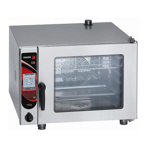
Fagor SBG9-10 User manual

Instrucciones generales para instalación, uso y mantenimiento
SARTEN BASCULANTE A GAS
Instructions générales pour l’instalation, l’utilisation et
l’entretien
SAUTEUSE BASCULANTE A GAZ
Allgemeine bedienungssanleitung zur installation, bedienung
und wartung
GAS-KIPPBRATPFANNE
General instructions for installation, use and maintenance
GAS TILTING BRATT PAN
Instruccioni generali per l´installzione, l´uso e la manutenzione
PADELLA BASCULANTE A GAS
Montaj, kullamin ve bakim için kullanim kilavuzu
GAZLI DEVRøLøR TAVA
Mod:
SBG9-10, SBG9-10 I
SBG9-10 S, SBG9-10 IS
SBG9-10 M, SBG9-10 IM,
SBG9-10 MS, SBG9-10 IMS,
SBG9-15 IMS
SBG9-15 IM X026501
SBG7-10 I

SBG9-10, SBG9-10I
SBG9-10 M, SBG9-10 IM, SBG9-15 IM
A: Water inlet
G: Gas inlet
E: Electricity point

SBG7-10

1 - SBG9-10, SBG9-10I, SBG9-10S, SBG9-10IS 2 - SBG9-10M, SBG9-10IM, SBG9-10MS,
SBG9-10I MS
3 - SBG9-15 IM, SBG9-15IMS 4 - SBG7-10

Fig. 9
Fig. 8

Dear customer
We would like to thank you for the confidence you have shown in our product on purchasing a professional
appliance. We are totally convinced that in time you will be completely satisfied with your purchase.
Take a few minutes of your time and get to know the appliance with this instructions manual and "down to
work": the easy to understand graphical information replaces pages full of writing.
Nevertheless, we recommend you to read this manual which has been compiled at length by FAGOR's
kitchen supervisors, in order to benefit to the maximum from the multiple possibilities and advantages that
this appliance offers you.
Keep this manual near to the appliance and at all times in an accessible place.
Lastly, we wish you success and hope that you will be fully satisfied with your new tilting bratt pan.
FAGOR
Idex
Installation
General and connection dimensions 1-2
Positionig and levelling 32
Electrical connection 32
Gas connection and conversion 32
Usage
Turning the appliance on 34
Turning the burners off 34
Maintenance
Maitenace 34
Environmental protection recommendation
Enviromental protection recomendation 34

Feature table(Table1)
RANGE
900
RANGE
700
MODEL SBG9-10
SBG9-10 I
SBG9-10 M
SBG9-10I M
SBG9-10 S
SBG9-10 IS
SBG9-10 MS
SBG9-10 IMS SBG9-15 I SBG9-15 IS SBG7-10 I
Width 850 850 850 850 850 850 700
Depth 900 900 900 900 900 900 775
OUTER
DIMENSIONS (mm)
Height 850 850 620 700 850 700 850
Width 780 780 780 780 1205 1205 630
Depth 660 660 660 660 660 660 510
Height 195 195 195 195 195 195 220
TUB
CHARACTERIS
TICS
(mm)
Capacity 60 60 60 60 120 120 55
NET WEIGHT (KG.) 195/175 195/175 190/175 190/170 235 230 111
NUMBER OF BURNERS 1 1 1 1 1 1 1
G-110 4.33 4.33 4.33 4.33 5.82 5.82 3,36
G-120 - - - - - - 2,99
G-130 2.55 2.55 2.55 2.55 3.43 3.43 1,98
G-150 3.35 3.35 3.35 3.35 4.50 4.50 2,60
G-20 1.78 1.78 1.78 1.78 2.65 2.65 1,38
G-25 2.07 2.07 2.07 2.07 3.08 3.08 1,60
G-25.1 - - - - - - 1,60
m3/h
GZ-35 - - - - - - 1,91
G-30 1.4 1.4 1.4 1.4 2.08 2.08 1,08
NOMINAL CONSUMPTION
Kg/h G-31 1.38 1.38 1.38 1.38 2.05 2.05 1,06
(L. calorific power.)
Kw/h 16.8 16.8 16.8 16.8 25 25 13
TOTAL
POWER (L. calorific power.)
Kw/h G25 / G25.1 11.5
VOLTAGE
POWER
HOSE
SECTION GENERAL FUSE DIFERENTIAL
DEVICE
230V 50-60Hz 2x1,5mm²+T 4A 30mA
ELÉCTRICAL TOTAL POWER KW 0,1Kw
Air consumption(Table2)
Mod. Consumption of necessary air for the combustion
Nm3/h
SBG9-10, SBG9-10I, SBG9-10S, SBG9-
10IS, SBG9-10 M, SBG9-10I M, SBG9-10
MS, SBG9-10I MS
19
SBG9-15IM, SBG9-15I MS 29
SGB7-10I 15
! "
a
! "


! "
a
! "
SBG9-10 M,
SBG9-10I M, SBG9-10 MS,
SBG9-10I MS,

Table of operating categories, gases and pressures(Table3)
RANGE 900
Country of destination Pressure (mbar) Categories
AT 20-50 II2H3B/P
BE, LU 20/25-28/37 II2E+3+
CH, IT 8-20,20-30/37 II1a2H,II2H3+
DE 20-50 II2E3B/P
DK 8-20-30 III1a2H3B/P
ES 8-18-28/37 III1ace2H3+
FI 20-30 II2H3B/P
FR 8-20/25-28/37 III1c2E+3+
GB, GR, IE 20-28/37 II2H3+
NL 25-30 II2L3B/P
NO, SE 8-20,20-30 II1A2H,II2H3B/P
PT 20-30/37 II2H3+
RANGE 700
Country of destination Categories Pressure (mbar)
AT II2H3B/P 20 ;50
BE II2E+3+ 20/25 ; 28-30/37
DE-LU II2E3B/P 20 ; 50
DK-SE III1a2H3B/P 8 ;20 ;30
ES III1ace2H3+ 8 ;20 ;28-30/37
FR III1c2E+3+ 8 ;20/25 ;28-30/37
FI-NO-LT-LV-EE-BG-RO-HR-
TR II2H3B/P 20 ;30
GB -PT-IE-CH-GR-SK-SI-CZ II2H3+ 20 ; 28-30/37
HU II2HS3B/P 25 ; 30
IT III1a2H3+ 8 ;20 ;28-30/37
MT-CY-IS I3B/P 30
NL II2L3B/P 25 ; 30
PL II2ELs3B/P 20 ;13 ;28-30
! "

! "


! "
a
! "
Bestimmungslan
d
# # # $ % &

Injector diameter and adjusment(Table4)
SBG9-10, SBG9-10I
SBG9-10 S, SBG9-10 IS
SBG9-10 M, SBG9-10 IM
SBG9-10 MS, SBG9-10 IMS
SBG9-15 IM
SBG9-15 IMS SBG7-10 I
BURNER PILOT BURNER PILOT BURNER PILOT
GAS
FAMILY
IInject
(mm)
H
(mm)
IInject
(mm)
IInject
(mm)
H
(mm)
IInject
(mm)
IInject
(mm)
H
(mm)
IInject
(mm)
G-110 4.58(x2) 14 ADJUSTABLE 4.58(x3) 14 ADJUSTABLE 3.9 (x2) 16 ADJUSTABLE
G-120 - - - - - - 3.9 (x2) 16 ADJUSTABLE
G-130 4.58(x2) 14 ADJUSTABLE 4.58(x3) 14 ADJUSTABLE 3.9 (x2) 16 ADJUSTABLE
1º
G-150 4.58(x2) 14 ADJUSTABLE 4.58(x3) 14 ADJUSTABLE 3.9 (x2) 16 ADJUSTABLE
G-20 2.15(x2) 19 ADJUSTABLE 2.15(x3) 19 ADJUSTABLE 1.9 (x2) 20 0.4
G-25 2.15(x2) 19 ADJUSTABLE 2.15(x3) 19 ADJUSTABLE 1.9 (x2) 18 0.4
G-25.1 - - - - - - 1.9 (x2) 18 0.4
2º
GZ-35 - - - - - - 2.6 (x2) 18 0.4
28 mbar 1.45(x2) 19 0.25 1.45(x3) 19 0.25 1.3 (x2) 22 0.25
G-30 50 mbar 1.25(x2) 16 0.20 1.25(x3) 16 0.20 1.15 (x2) 22 0.20
37 mbar 1.45(x2) 19 0.25 1.45(x3) 19 0.25 1.3 (x2) 22 0.25
3º
G-31 50 mbar 1.25(x2) 16 0.20 1.25(x3) 16 0.20 1.15 (x2) 22 0.20
Approximate positions and temperatures(Table5)
Control position 1. 2 3 4 5 6 7 8
Temperature 50 ºC 80 ºC 120
ºC
160
ºC
200
ºC
230
ºC
270
ºC
300
ºC
! "


Cuadro N° 1

! "

! "


! "


! "
a
! "
6

1.-INSTALLATION
Positioning and levelling
The positioning and electrical and gas installation should always be carried out by an AUTHORISED
TECHNICIAN, observing the standards of each country.
It is advisable to install an extraction hood for the optimum operation of the appliance.
Place the appliance in a well ventilated place.
Level and adjust the height of the appliance. (Fig. 1)
The appliance's electrical connection should always be carried out by an AUTHORISED TECHNICIAN.
The legal standards in force in each country on connections to the mains should be taken into account.
Check that the mains voltage corresponds to that indicated on the name plate.
Use polychloroprene cable sleeves or other similar materials (Ho5RN-F) for the connection.
A switch device should be installed next to the appliance for all the phases, with a gap of a minimum of 3 mm between
contacts. This switch will be equipped with fuses.
It is obligatory to earth the appliance. The manufacturer takes no responsibility if this requirement is not fulfilled.
The section of cable sleeve and the rating of the fuses to be installed in the power switch are indicated in
Table no. 1.
To access the appliance's electrical connection terminal strip (see Fig. 2),loosen screws (3) on box 1 and
terminal strip lid 2 and remove the box through the lower part of the front panel. Pass the cable sleeve
through the stuffing box 4 located in the switchboard and connect it to the terminal strip.
VERY IMPORTANT: Before putting the switchboard top on, fasten the electric supply cable tightly to the
stuffing box.
When several appliances are installed in series, they should be earthed to each other using the point
assigned for this purpose, located in the appliance's base, at the back
The general installation should have a stopcock and a pressure regulator and it also advisable to install a
shut-off cock on each individual appliance.
Conversion to different gases
If the appliance is prepared for a different type of gas to the one available, you should proceed as follows:
Cut off the gas to the appliance if connected. (All conversions of the appliance's gas circuit must always be
carried out by a QUALIFIED TECHNICIAN).
Burner conversion
Injector replacement.
Dismantle the burners' “A” injectors (Fig. 3) and replace them with suitable ones depending of the gas to
be used (Table 4)
Burner air adjustment.
Position the air regulator “B” (Fig. 3) to the “H” measurement (Table 4) depending on the gas to be used.
Pilot light conversion
Injector replacement
To convert to a different type of gas, please proceed as follows:
- Take off the lid “A” underneath which is the injector “B” to be removed and replace if with the injector
corresponding to the type of gas to be used (tighten it completely) according to Fig. 4 (Detail A).
- Turn the air regulator “C” until the flame stabilises
'
( ) * + + ,
Después de la adaptación del aparato a otro tipo de gas o a otra presión, distintas de aquellas para las
cuales habia sido anteriormente regulado, las indicaciones del nuevo reglaje deberan colocarse en lugar
y en la posición de las indicaciones precedentes, de forma que permitan la identificación sin ambigüedad
del estado del aparato después de la intervención.
! "
2
! "
2

2.-USAGE
Never start the appliance empty, as overheating could seriously damage the tub.
1.-SBG9-10, SBG9-10I, SBG9-10S, SBG9-10IS 2.-SBG9-10M, SBG9-10IM, SBG9-10MS, SBG9-10I
MS
SBG9-15 IM, SBG9-15I MS 4.-SBG7-10
Burner ignition
Open the main general gas-tap installed on the outside of the appliance.
1st Step Pilot Light Ignition
Turn the thermostat Mt control (Fig. 5) clockwise until the pilot light position (Fig. 7 - P1), at this moment the
“L1” lamp will light up (Fig. 5) indicating that it is ready for the “P” pilot light to be ignited (Fig. 5).
Next, press the solenoid valve Mv control (Fig. 5), whilst turning anti-clockwise to the pilot light position (Fig.
6 - P1). In this position, keep pressing the control until the “P” pilot light flame (Fig. 5) is permanently lit
(approximately 20 seconds).
2nd Step Ignition of burners
Pressing the solenoid valve control Mv (Fig. 5), rotate to burners ignition position (Fig. 6 - P2), it is ready
for the burners to be ignited.
To ignite the burners, press and turn the “Mt” thermostat control (Fig. 5) clockwise until the required
position, (Fig. 7, and). At this moment the “L2” lamp will light, indicating that the burners are functioning.
The required oil temperature (approximate) can be achieved turning the “Mt” control to selected position
(see table 3 for temperatures, indicating the temperature corresponding to each position on the control).
When the oil in the tub reaches the selected temperature, the burners will turn off by means of the
thermostat (lamp “L2” turns off). Also, as soon as the temperature drops below the selected value, the
burners will light up (switching on the L2 lamp).
Turing the burners off
Move from the position selected on the “Mt” control to the pilot light position (Fig. 9 - P1), so that only the
“P” pilot light is on (Fig. 7).
Turning the pilot light off
Move the “Mv” control to the “0” position (Fig. 8 - P0) and also move the “Mt” thermostat control to the “0”
position (Fig. 9 - P0).
1.- Water inlet tap.
2.- On lamp.
3.- Pilot light position lamp.
4.- Thermostat control.
5.- Gas tap control.
6.- Observation peep-hole on.
7.- Tub raising handle.
8.- Manual ignition hole.
1.- Water inlet tap.
2.- On lamp.
3.- Pilot light position lamp.
4.- Thermos-tat control.
5.- Gas tap control.
6.- Observation peep-hole on.
7.- Raise-lower switch.
8.- Manual ignition hole.
1.- Water inlet tap.
2.- On lamp.
3.- Pilot light position lamp.
4.- Thermostat control.
5.- Gas tap control.
6.- Observation peep-hole on.
7.- Raise-lower switch.
8.- Manual ignition hole.
1.- Tub raising handle .
2.- Manual ignition hole.
3.- Observation peep-hole on.
4.- Gas tap control.
5.- Thermos-tat control.
6.- On lamp.
7.- Pilot light position lamp.
8.- Water inlet tap.
! "


! "


3.-MAINTENANCE
Daily cleaning
In order for the appliance to work as new, it is advisable to follow the following instructions:
Do not use gritty and abrasive detergents for cleaning.
Do not use a water hose to clean the appliance.
It is advisable to regularly clean the inner part of the tub with soapy water that will be left to boil for a few
minutes, and then rinse it with plenty of water.
It is important that as soon as the tub has been cleaned and before filling it with oil, it be completely dry
without a sign of water.
IMPORTANT NOTE:
The replacement of any functional component that can affect the safety of the appliance must be carried
out by an AUTHORISED TECHNICIAN.
As a general rule, whenever an operating component is replaced, you must check that the main gas-tap is
shut and that is no fire in the vicinity of the appliance.
Do not scratch the stainless steel surfaces with spatulas or iron wire brushes.
If they are not going to be used for a long while, cover the surfaces with a thin layer of Vaseline, above all
inside the tub.
4.-ENVIRONMENTAL PROTECTION RECOMMENDATION
On ending its useful life, this product must not be thrown away in a standard
rubbish bin, but must be left in a electrical waste and electronic equipment collection
point for recycling.
This is confirmed by the symbol on the product, user manual or packaging.
Depending on the symbol, the materials can be recycled. By recycling and other ways
of processing electrical waste and electronic equipment, you can significantly
contribute to protecting the environment.
Contact your local authorities for more information of the nearest collection point.
To conserve the environment at the end of the useful life of your product, leave it in the
appropriate places in accordance with the current legislation.
NOTE: THE FINAL HOLDER OF THE CONTAINER WASTE IS RESPONSIBLE FOR ITS
MANAGEMENT.
This appliance is only for professional usage and must
be used by qualified personnel
This manual suits for next models
10
Table of contents
Other Fagor Commercial Food Equipment manuals
Popular Commercial Food Equipment manuals by other brands

Diamond
Diamond AL1TB/H2-R2 Installation, Operating and Maintenance Instruction

Salva
Salva IVERPAN FC-18 User instructions

Allure
Allure Melanger JR6t Operator's manual

saro
saro FKT 935 operating instructions

Hussmann
Hussmann Rear Roll-in Dairy Installation & operation manual

Cornelius
Cornelius IDC PRO 255 Service manual

Moduline
Moduline HSH E Series Service manual

MINERVA OMEGA
MINERVA OMEGA DERBY 270 operating instructions

Diamond
Diamond OPTIMA 700 Installation, use and maintenance instructions

Diamond
Diamond G9/PLCA4 operating instructions

Cuppone
Cuppone BERNINI BRN 280 Installation

Arneg
Arneg Atlanta Direction for Installation and Use