Fagor FI-200W L User manual

1
0TABLE OF CONTENTS
0 TABLE OF CONTENTS _____________________________________________________ 1
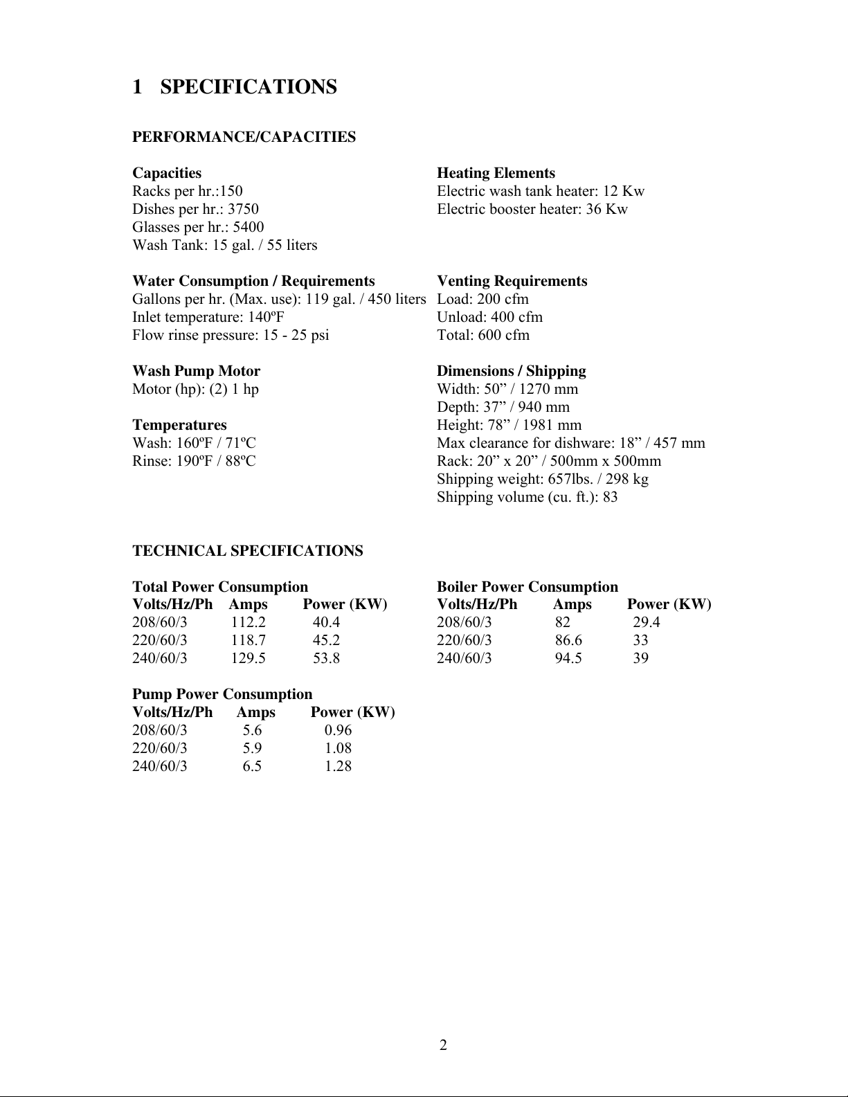
1 SPECIFICATIONS __________________________________________________________ 2
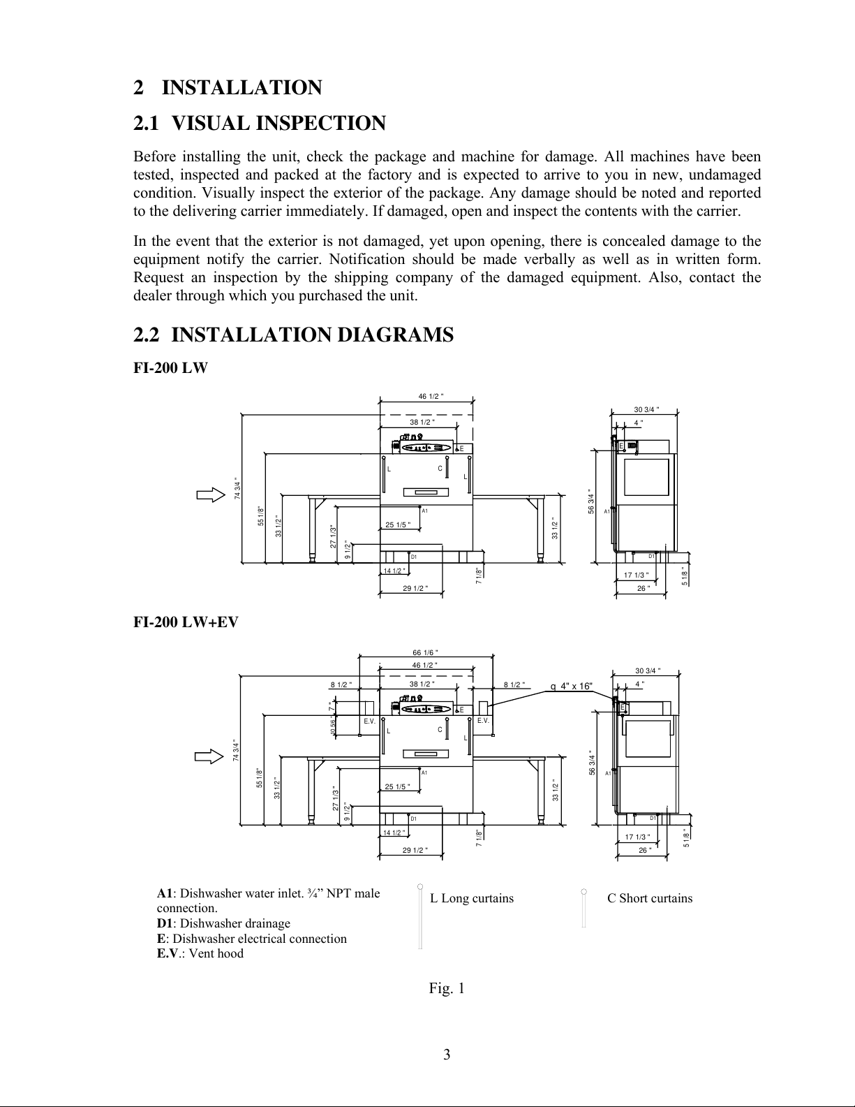
2 INSTALLATION ___________________________________________________________ 3
2.1 VISUAL INSPECTION __________________________________________________ 3
2.2 INSTALLATION DIAGRAMS ____________________________________________ 3
2.3 DATA PLATE _________________________________________________________ 4
2.4 POSITIONING _________________________________________________________ 4
2.5 WATER INSTALLATION________________________________________________ 4
2.6 WATER DRAINAGE____________________________________________________ 6
2.7 ELECTRICAL CONNECTION ____________________________________________ 6
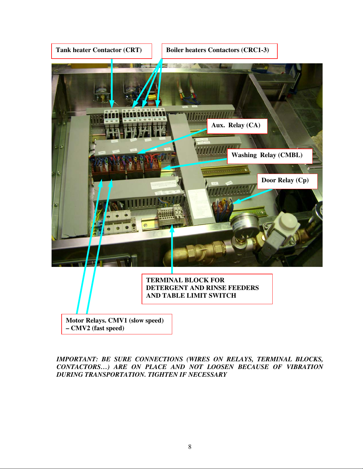
2.8 CHEMICAL AND TABLE LIMIT SWITCH CONNECTIONS___________________ 7
3 INSTALLATION / START UP CHECKLIST_____________________________________ 9
4 USE _____________________________________________________________________ 10
4.1 USE OF THE APPLIANCE ______________________________________________ 10
4.2 ADVICE ON HOW TO WASH CORRECTLY_______________________________ 11
5 MAINTENANCE __________________________________________________________ 13
6 CLUTCH AJUSTMENT_____________________________________________________ 14
7 TROUBLESHOOTING _____________________________________________________ 15
8ELECTRICAL DIAGRAM __________________________________________________ 18
9COMPONENTS ___________________________________________________________ 19
10 WIRING SCHEMATIC _____________________________________________________ 20
11 RECOMMENDED SPARE PARTS____________________________________________ 21
12 FAGOR COMMERCIAL LIMITED WARRANTY _______________________________ 22
WARNING: Improper installation, adjustment, alteration, service or maintenance can cause
property damage, injury or death. Read this manual thoroughly before installing or servicing this
equipment. We recommend all service performed by an authorized service technician. Follow the
instructions and guidelines to ensure that your warranty remains in effect.
FOR START UP OF THE MACHINE GO THROUGH POINTS 3, 4 AND 5, IN ORDER TO
BE SURE THAT THE INSTALLATION HAS BEEN DONE PROPERLY AND IN ORDER TO
FAMILIARIZE THE ENDUSER WITH THE MACHINE REGARDING USE AND
MAINTENANCE OF THE MACHINE.
https://appliancetechmanuals.com

2
1SPECIFICATIONS
PERFORMANCE/CAPACITIES
Capacities Heating Elements
Racks per hr.:150 Electric wash tank heater: 12 Kw
Dishes per hr.: 3750 Electric booster heater: 36 Kw
Glasses per hr.: 5400
Wash Tank: 15 gal. / 55 liters
Water Consumption / Requirements Venting Requirements
Gallons per hr. (Max. use): 119 gal. / 450 liters Load: 200 cfm
Inlet temperature: 140ºF Unload: 400 cfm
Flow rinse pressure: 15 - 25 psi Total: 600 cfm
Wash Pump Motor Dimensions / Shipping
Motor (hp): (2) 1 hp Width: 50” / 1270 mm
Depth: 37” / 940 mm
Temperatures Height: 78” / 1981 mm
Wash: 160ºF / 71ºC Max clearance for dishware: 18” / 457 mm
Rinse: 190ºF / 88ºC Rack: 20” x 20” / 500mm x 500mm
Shipping weight: 657lbs. / 298 kg
Shipping volume (cu. ft.): 83
TECHNICAL SPECIFICATIONS
Total Power Consumption Boiler Power Consumption
Volts/Hz/Ph Amps Power (KW) Volts/Hz/Ph Amps Power (KW)
208/60/3 112.2 40.4 208/60/3 82 29.4
220/60/3 118.7 45.2 220/60/3 86.6 33
240/60/3 129.5 53.8 240/60/3 94.5 39
Pump Power Consumption
Volts/Hz/Ph Amps Power (KW)
208/60/3 5.6 0.96
220/60/3 5.9 1.08
240/60/3 6.5 1.28
https://appliancetechmanuals.com

3
2INSTALLATION
2.1 VISUAL INSPECTION
Before installing the unit, check the package and machine for damage. All machines have been
tested, inspected and packed at the factory and is expected to arrive to you in new, undamaged
condition. Visually inspect the exterior of the package. Any damage should be noted and reported
to the delivering carrier immediately. If damaged, open and inspect the contents with the carrier.
In the event that the exterior is not damaged, yet upon opening, there is concealed damage to the
equipment notify the carrier. Notification should be made verbally as well as in written form.
Request an inspection by the shipping company of the damaged equipment. Also, contact the
dealer through which you purchased the unit.
2.2 INSTALLATION DIAGRAMS
FI-200 LW
D1
A1
L
E
C
L
E
A1
D1
38 1/2 "
14 1/2 "
29 1/2 "
74 3/4 "
55 1/8"
33 1/2 "
4 "
56 3/4 "
25 1/5 "
27 1/3"
46 1/2 "
9 1/2 "
7 1/8"
33 1/2 "
30 3/4 "
17 1/3 "
26 "
5 1/8 "
FI-200 LW+EV
D1
A1
L
E
C
L
E
A1
D1
25 1/5 "
27 1/3 "
8 1/2 " 8 1/2 "
66 1/6 "
E.V. E.V.
10 5/6 "
38 1/2 "
14 1/2 "
29 1/2 "
74 3/4 "
55 1/8"
33 1/2 "
4 "
56 3/4 "
9 1/2 "
7 1/8"
33 1/2 "
30 3/4 "
17 1/3 "
26 "
5 1/8 "
46 1/2 "
7 "
q 4" x 16"
A1: Dishwasher water inlet. ¾” NPT male
connection.
D1: Dishwasher drainage
E: Dishwasher electrical connection
E.V.: Vent hood
Fig. 1
C Short curtainsL Long curtains
https://appliancetechmanuals.com

4
2.3 DATA PLATE
The data plate is located on one side of the machine. Under no circumstances should the data plate
be removed from the unit. The data plate is essential to identify the particular features of your
machine and is of great benefit to installers, operators and maintenance personnel. It is
recommended that, in the event the data plate is removed, you copy down the essential information
in this manual for reference before installation. Any transformations or changes made on the
machines during installation should be reflected on the data plate.
2.4 POSITIONING
Fig.2
Leveling and adjusting the height of the appliance is done by turning the leveling stands (Fig. 2) to
the desire height. Ensure that the unit is level before making any connections
2.5 WATER INSTALLATION
Water installation is carried out as shown in figures 3 and 4. The hot water line to the dishwasher
must provide between 20±5psi of flow rinse pressure. Operational wise, machine will work fine up
to 40 psi water pressure. The hot water heater should be set to deliver ≥140°F (≥60°C) water
temperature to the dishwasher for best results. Use ¾” copper tubing inlet line.
CAUTION: Do not confuse static pressure with flow pressure. Static pressure is the line pressure
in a “no flow” condition (all valves and services are closed). Flow pressure is the pressure in the
fill line when the solenoid valve is opened during the cycle.
Pressure gauge shall have increments of 1 psi or smaller and shall be accurate to ±2 psi in the 15-
25 psi range. The display of the pressure shall be clearly visible to the operator of the machine.
If the water pressure is less than 20 psi (1.4 kg/cm2), installation of a water pump is required as
shown in Fig. 4. In areas where the pressure fluctuates or is greater than the recommended
pressure, it is suggested that a water pressure regulator be installed.
It is necessary to remove all foreign debris from the water line that may potentially get trapped in
the valves or cause an obstruction, prior to connecting to the machine.
FOR HARD WATER SUPPLIES WITH A HARDNESS OF OVER 2 GRAINS OR 10ºF AND
PH BEYOND THE RANGE OF 7.0 – 8.5, A WATER CONDITIONER MUST BE INSTALLED.
https://appliancetechmanuals.com

5
Slowly turn on the water supply to the machine after the incoming fill line and the drain line have
been installed. Check for any leaks and repair as required. All leaks must be repaired prior to
placing the machine in operation.
Z718417000
Pressure Gauge
Z718418000 Vacuum breakerZ718415000 Water valve
Z102308000
Filter 3/4"
Z602121000 Water hose
connected to the boiler.
Z102307000
Pressure reducer
¾” Water connection. Hose +
gasket must be fitted here.
Wiring for water solenoid
valve. Be sure it is connected
https://appliancetechmanuals.com

6
2.6 WATER DRAINAGE
Attach the drain hose as shown in Fig. 5. It is recommended to affix a siphon pipe to prevent
odors. All piping from the machine to the drain must be a minimum 1-1/2” I.P.S. There should also
be an air gap between the machine drain line and the drain. For natural overflow efficiency use
floor drain.
D= Drain hose
C= Drain collector
F= Scrap Basket
Fig.5
2.7 ELECTRICAL CONNECTION
−To access to the electrical terminal block (E) (Fig. 1), remove the top cover. Connect the wires
as shown in figure 6. Insert the power cord through the cord guide on the back of the machine
and make sure to leave enough cable. Tighten the connections.
−Leave free ≥39” (≥1000 mm) of power cord from the rear to facilitate cleaning of the location
of the dishwasher.
−Install a circuit breaker in accordance to required consumption guidelines and data plate.
−The machine must be grounded.
WARNING: Electrical Shock Hazard
It is the personal responsibility and obligation of the customer to contact a qualified electrician to
assure that the electrical installation is adequate and is in conformance with the National Electrical
Code, ANSI / NFPA 70 – latest edition and all local codes and ordinance.
FI-200W L and FI-200W R
208-240Volts / 3 phases
G
L1
L2
L3
am/ve
a
m
g
n
Fig.6
am/ve: yellow/green; a:blue; n: black; m: brown; g: grey
https://appliancetechmanuals.com

7
2.8 CHEMICAL AND TABLE LIMIT SWITCH CONNECTIONS
This machine must be operated with an automatic detergent feeder and, if applicable, an automatic
chemical sanitizer feeder, including a visual means to verify that detergents and sanitizers are
delivered or a visual or audible alarm to signal if detergents and sanitizers are not available for
delivery to respective washing and sanitizing systems. Please see instructions for electrical and
plumbing connections located in this manual and in the feeder equipment manual.
Fagor does not recommend any brand name of chemicals or chemical dispensing equipment.
Contact your local chemical distributor for questions concerning these subjects.
To access to the connections terminal block, remove the top cover. See figure 7 to connect
electrically detergent and rinse feeders. To connect the table limit switch (safety end switch)
FIRST remove bridge wire between terminals 4 & 5 and then connect the switch.
Fig.7
Z312941000 Terminal block. 3 phases connection
Power cord must go through
this
TERMINAL BOX
Ground terminal
https://appliancetechmanuals.com

8
IMPORTANT: BE SURE CONNECTIONS (WIRES ON RELAYS, TERMINAL BLOCKS,
CONTACTORS…) ARE ON PLACE AND NOT LOOSEN BECAUSE OF VIBRATION
DURING TRANSPORTATION. TIGHTEN IF NECESSARY
TERMINAL BLOCK FOR
DETERGENT AND RINSE FEEDERS
AND TABLE LIMIT SWITCH
Door Relay (Cp)
Tank heater Contactor (CRT) Boiler heaters Contactors (CRC1-3)
Motor Relays. CMV1 (slow speed)
– CMV2 (fast speed)
Washing Relay (CMBL)
Aux. Relay (CA)
https://appliancetechmanuals.com

9
3INSTALLATION / START UP CHECKLIST
CHECK OFF THE FOLLOWING ITEMS AS THEY ARE COMPLETED
BEFORE PROCEEDING TO OPERATE OR SERVICE THE DISHWASHER.
Has the dishwasher been checked for concealed/hidden damage?
Has the dishwasher been properly leveled?
Has the service voltage been checked to ensure that it meets the
requirements listed on the dishwasher data plate?
Has the dishwasher circuit breaker/service breaker been sized correctly,
given the dishwasher’s amperage requirements?
Has the dishwasher been properly grounded?
Is the water valve open?
Is the incoming water supply at 20 - 40 psi?
Is the incoming water supply line at ¾” minimum?
Has been installed with the supplied water hose?
Is the water hose not kinked?
Has the incoming water supply been flushed for debris?
Is the hot water supply at the minimum recommended temperature ?
Is the water hardness ≤2.0gpg/34.2ppm and PH level 7 - 8.5ph ?
Has the drain plumbing been installed according to the instructions in this
manual?
Is the drain hose not kinked?
Is the overflow tube with the O-ring fitted in its position inside the tank?
Is the table limit switch connected as indicated on the instructions?
Are the detergent and rinse feeders connected as indicated on the
instructions?
MODEL NO.___________________________
SERIAL NO.___________________________
INSTALLATION DATE _________________
SERVICE REP. NAME __________________
PHONE Nº ____________________________
https://appliancetechmanuals.com

10
4 USE
4.1 USE OF THE APPLIANCE
FI-200W L and FI-200W R
1st. FILLING. Set the selector dial (1), (Fig. 8) to the preparation position (∇) (2). The pilot light
will come on (3) and the filling of the of the Boiler and the wash tank will start.
Once full of water, turn the right thermostat control to 90ºC (Fig. 8).
This operation will be only carried out when the appliance is installed for the first time or when the
Boiler resistances are changed.
FURTHER FILLINGS.Set the selector dial (1), (Fig. 8) to the preparation position (∇) (2). The
pilot light will come on (3) and the filling and heating of the rinse and wash water starts. The
appliance is ready when the rinse thermometer (4) displays158÷185ºF / 70÷85ºC and the wash
thermometer (5) displays160ºF/71ºC.
When the wash pumps work the rinse thermometer (4) will indicate 185÷194ºF/85÷92ºC.
Motor has 2 advance speeds. Depending on the speed selection CMV1 or CMV2 relay will be
activited, but only one. The signal that the motor will receive is different if it comes through one or
the other:
− Selector set to position (I), slow speed for a more intense wash. (Fig.8)
− Selector set to position (II), fast speed to wash less dirty crockery. (Fig.8)
When the advance is activated the pilot light comes on (6)
Separate starter switches ensure wash and rinse are energized only when a rack is in place,
reducing water and chemical consumption.
Fig.8
0
160°F.....167°F 185°F.....194°F
3612
5
45
https://appliancetechmanuals.com

11
4.2 ADVICE ON HOW TO WASH CORRECTLY
Before washing.
Be sure that:
−The washing tub filters and pump suction filters are in place.
−The overflow tube is place.
−The curtains are placed correctly.
−The door is closed.
−The detergent and rinse-aid dispensers are full.
−The dimensions of the items to be washed are not greater than the dishwasher’s working
dimensions.
Preparing the crockery
-Remove big pieces of food from dishes before putting them in the baskets.
-Wash glassware first.
-Put plates in the baskets, making sure each is in its separate rack (Fig. 10).
-Put glasses in upside down.
-Put cutlery in the cutlery baskets handles down. Spoons, knives and forks can be mixed (Fig.9)
-Put the special cutlery baskets in the base baskets.
Fig. 9
Fig.10
During the washing cycle.
−Only use commercial grade detergent low suds, supplied by well-respected companies.
−Put the amount of detergent recommended by the manufacturer.
−Disconnect the machine if it does not work correctly or there is a fault. For any eventual repair,
only use an authorised technical assistance centre and request the use of original parts.
−Stop the machine periodically, remove the filters from the tub and clean the residues that are
deposited on them. Do not remove the suction filter from the pump (Fig. 12) when the tub is
full.
−Check the level of detergent and rinse-aid in their respective containers.
After the washing cycle.
−Turn the switch to position “0” to turn the machine off (Fig. 8).
−Open the door and secure it with the fixing stop.
−Remove the overflow tube to empty the washing tub (Fig.11).
−Drain the machine everyday at the end of the day.
−When the tub is empty, remove the curtains and the filters to clean them appropriately (Fig. 12
and Fig. 13).
https://appliancetechmanuals.com

12
Fig.11
Fig.12
−Clean the washing and rinsing injectors
−Clean the tub appropriately with a water jet, removing all the residues that are stuck to it.
−Clean the racks daily.
Fig. 13
−Re-assemble all the devices in their correct place, keeping in mind the following:
−The short side of curtains should face towards the dishes entrance.
−The nozzles should be aimed towards the dishes.
−Keep the door open to avoid bad smells forming.
Saving energy
−The machine only works when racks are put in.
Dispensers
−Detergent and rinse aid dispensers are not supplied with the machine. These are necessary for a
correct final wash and rinse.
−The conections between the detergent doser, the rinse doser and the safety end switch with the
binding clamp should be done as shown in figure 7
Table limit switch (safety end switch)
−This safety switch is to avoid rack jam at exit table if it is required. See fig.7 for electric
connection.
https://appliancetechmanuals.com

13
5MAINTENANCE
Regular wiping of the outside surface with a soft, damp sponge or cloth and mild detergent is
all that is necessary to maintain the good looks of your dishwasher.
−Check the rinse aid and detergent dispenser from time to time and refill when necessary.
−Check and clean the injectors frequently, see figures 14,15 and 16.
Fig.14
Fig.15 Fig.16
−If the machine is not going to be used for a long time, cover its surfaces with a coating of
petroleum jelly.
−Do not use the machine to wash iron objects.
−Do not use corrosive products, such as hypo-sodium chloride (bleach), hydrochloric acid, acids
in general, steel wool or scrapers, for the internal and external cleaning of the machines.
Prolonged disuse of the machine:
If the machine is not used for a long time it is advisable to start the machine with clean water while
it is empty, to avoid unpleasant smells forming and dirt accumulating.
https://appliancetechmanuals.com

14
6CLUTCH AJUSTMENT
If it was necessary to adjust the clutch, proceed as follows:
Loosen the bolt on the top of the clutch with a no. 13 wrench and with a no. 4 Allen wrench, loosen
the side bolt. (Fig 17, Fig. 18)
With a torque wrench adjusted to 12 Nm and a “C” wrench (Fig. 19) which will hook onto one of
the lateral holes of the clutch, tighten this clockwise until the torque wrench indicates that the
required torque has been reached (the end of the wrench “clicks”). (Fig. 20).
Once this has been done, tighten the top and lateral bolts. (Fig 19, Fig. 20)
Should a torque wrench not be available, tighten only with the “C” wrench and then check the
tightness with the dishwasher loaded with baskets and dishes.
Tighten
Loosen
Fig. 18
Torque wrench
“C” Wrench
Fig. 19
Tighten
Fig. 20
Fig. 20
Top bolt
Side bolt
Fig. 17
https://appliancetechmanuals.com

15
7TROUBLESHOOTING
First be sure that the “Installation Checklist” in this manual was completed and check out that all
the items still remains in effect. For support or further service information contact Fagor Service
Department toll free at 1-866-GO-FAGOR (46-32467). The diagnosing, testing and repair of any
electrical, mechanical device is to be performed solely by trained service technicians.
SYMPTOM POSSIBLE CAUSE ACTION
Service breaker tripped Reset. If the breaker trips again, contact an
electrician to verify amps or possible short.
Machine not connected to
power source.
Verify the unit is connected to a hot (live)
feed. Verify voltage and proper phasing.
Faulty selector switch (Ig) Verify the wiring of the switch; if correct,
replace the switch. (Position 1-1a / 2-2a)
Dishwasher will NOT
FILL after the door is
closed. Selector in∇
position, light is not
illuminated.
Fuses blown up Check out fuses. Replace if neccessary.
No water to machine Verify hose is not blocked or kinked, water
valve is open and pressure > 20 PSI.
Overflow tube not
attached or broken /
missing O-ring.
Check condition of overflow tube.
Faulty door switch Verify the wiring of the switch; if correct,
replace the switch (Ip) or the door relay
(Cp)
Dishwasher will NOT
FILL after the door is
closed. Selector in
preparation (∇) position.
Power “ON” light (L1)
is illuminated.
Faulty fill valve (VA) Verify the wiring and voltage received; if
correct replace fill valve.
Fill pressure switch’s pipe
clogged
Drain the unit and fill again
Faulty fill pressure switch
(P12)
Verify position change 1-2 / 1-3 to
pressure switch. Possibly stuck
Faulty door switch Verify the wiring of the switch; if correct,
replace the switch (Ip) or the door relay
(Cp)
Faulty selector switch (Ig) Verify the wiring of the switch; if correct,
replace the switch. (Position 3-3a / 4-4a)
Faulty motor relay
(CMV1/CMV2)
Ohm out relay, closed when solenoid
receiving voltage. If not replace .
Dishwasher will NOT
RUN after the door is
closed. Selector in
advance position,
Power “ON” light (L1)
is illuminated., the unit
has completed the filling
and heating cycle.
Faulty motor (MV1/MV2) Verify the wiring and voltage received;
Replace if necessary.
Faulty selector switch (Ig) Verify the wiring of the switch; if correct,
replace the switch. (Position 5-5a)
Faulty washing switch
(IL)
Verify it changes position of the switch; If
not replace it.
Dishwasher will NOT
WASH after the door is
closed. Selector in
advance position, Power
“ON” light (L1) is
illuminated, the unit has Faulty wash pump relay
(CMBL)
Ohm out relay, closed when solenoid
receiving voltage. If not replace .
https://appliancetechmanuals.com

16
completed the filling
and heating cycle,
conveyor moving and a
rack is in wash area.
Faulty wash pump (MBL1
& MBL2)
Verify that the wash pump is getting
power. If so, replace the pump. Ohm out
windings.
Faulty selector switch (Ig) Verify the wiring of the switch; if correct,
replace the switch. (Position 5-5a)
Faulty washing switch
(Ia)
Verify it changes position of the switch; If
not replace it.
Faulty rinsing relay (CA) Ohm out relay, closed when solenoid
receiving voltage. If not replace .
Faulty rinse valve (VA) Verify the wiring and voltage received; if
correct, ohm out. If open replace valve.
Dishwasher will NOT
RINSE after the door is
closed. Selector in
advance position, Power
“ON” light (L1) is
illuminated, the unit has
completed the filling
and heating cycle,
conveyor moving and a
rack is in RINSE area.
No water to machine. Verify hose is not blocked or kinked, water
valve is open and pressure > 20 PSI.
Clogged or obstructed
rinse arms
Remove and clean rinse arms/nozzles.
Poor water pressure Verify the inlet water pressure is at a min
of 20 psi and max 40 psi.
Hose strainer is clogged Check strainer or any filters installed.
Dishwasher FILLS
slowly and/or rinse is
weak.
Bad fill valve (VA) Valve can be clogged or lazy, causing poor
flow.
Temperature gauge in
front panel is defective.
Check temperature with a calibrated
thermometer. Replace temperature gauge if
necessary.
Misadjusted/faulty
thermostat (Tt)
Verify operation and setting of thermostat;
replace if necessary. If thermostat is not
receiving voltage, check wiring.
Faulty heater contactor
(CRT)
Ohm out tank contactor, closed when
solenoid receiving voltage. If not replace .
Dishwasher RUNS.
WASH WATER NOT
REACHING
REQUIRED
TEMPERATURE.
Tank heating element
(RT) faulty.
Ohm out element check for continuity; if
open, replace heater.
Temperature gauge in
front panel is defective.
Check temperature with a calibrated
thermometer. Replace temperature gauge if
necessary.
Faulty fill pressure switch
(P11)
Verify position change 1-3 to pressure
switch. Possibly stuck.
Misadjusted/faulty
thermostat (Tc)
Verify operation and setting of thermostat;
replace if necessary. If thermostat is not
receiving voltage, check wiring
Faulty high limit stat
(Tsc)
Reset thermostat, depressing red button.
Replace if necessary.
Faulty heater contactors
(CRC1, CRC2, CRC3)
Ohm out booster contactors, closed when
solenoid receiving voltage. If not replace .
Dishwasher RUNS.
RINSE WATER NOT
REACHING
REQUIRED
TEMPERATURE.
Rinse heater (RC1, RC2,
RC3) faulty
Ohm out element check for continuity; if
open, replace heater.
Dishes are not coming
out clean enough.
Machine temperatures or
pressure may not be to
specification.
Verify that the water pressure is at a min.
of 20psi and max 40 psi. The water
temperature should be at the recommended
140º F.
https://appliancetechmanuals.com

17
None or too little
detergent being used.
Make sure detergent to dish ratio is
fallowed to manufacturer specification.
Improper loading or
overloading
Read chapter on proper loading of
dishwasher.
(Cont.)
Washing and or rinsing
arms jammed or dirty.
Check that arms rotate properly, and that
rinsing and washing nozzles are not
blocked or dirty. Clean if necessary
https://appliancetechmanuals.com

18
8ELECTRICAL DIAGRAM
CMBL
m
m
a
1
MBL
2
MBL
C1
n
C2
CMBL
FI-200 W
n
(208÷240)V
CRC1
RC1 RC2 RT
R
S
T
g
m
n
MV1
M
3~
CRC2
RC3
MV2
CMV1 CMV2
CRC3
n
nm
mg
g
nm
g
CRC1 CRC2 CRC3
m
ng
nm
g
CRC1 CRC2 CRC3
nmg
CRT
nmg
g
m
n
nmg
nmg
nmg
nm g
CA
m
aF
22a
11a
VE
L1
rs
TC
90
TSC
vi
CR
C1
CR
C2
CR
C3
g
IP
vi
ve
r
m
b
am
rs
b
CRT
Tt
na
CA
PT
12
CMV1CMV2
vi
b
3
3a
4
4a
L2
IL
Ia
am
na
g
am
5
5a CP
CA VA MBP DS
DET
DS
ABR
n
F
1
3
rs
FMV
4
SF
rs
5
rs
CP
g
a
1
3
1
32
PT
11
Z273058000
0
XX
XXX
X
X
X
X
X
X
5a
5
4a
43
3a2a
2
2
V
1
V
X
1a
1
IG
2
V
1
V
0
g
CP
2
TC
70
na
CA
CM
BL
https://appliancetechmanuals.com

8 ELECTRICAL DIAGRAM
CMBL
m
m
a
1
MBL
2
MBL
C1
n
C2
CMBL
FI-200 W
n
(208÷240)V
CRC1
RC1 RC2 RT
R
S
T
g
m
n
MV1
M
3~
CRC2
RC3
MV2
CMV1 CMV2
CRC3
n
nm
mg
g
nmg
CRC1 CRC2 CRC3
m
ng
nmg
CRC1 CRC2 CRC3
nmg
CRT
nmg
g
m
n
nmg
nmg
nmg
nm g
CA
m
aF
22a
11a
VE
L1
rs
TC
90
TSC
vi
CR
C1
CR
C2
CR
C3
g
IP
vi
ve
r
m
b
am
rs
b
CRT
Tt
na
CA
PT
12
CMV1CMV2
vi
b
3
3a
4
4a
L2
IL
Ia
am
na
g
am
5
5a CP
CA VA MBP DS
DET
DS
ABR
n
F
1
3
rs
FMV
4
SF
rs
5
rs
CP
g
a
1
32
Z273058000
0
XX
XXX
X
X
X
X
X
X
5a
5
4a
43
3a2a
2
2
V
1
V
X
1a
1
IG
2
V
1
V
0
g
CP
2
TC
70
na
CA
CM
BL
r
rs
https://appliancetechmanuals.com
This manual suits for next models
1
Table of contents
Other Fagor Dishwasher manuals

Fagor
Fagor IO-DWS-2841 User manual

Fagor
Fagor LVF453ITA User manual

Fagor
Fagor AD-21BDD User manual

Fagor
Fagor 3LVF-435 User manual

Fagor
Fagor WC-46 DZ User manual

Fagor
Fagor FI - 48 W Parts list manual

Fagor
Fagor 3LVF-423 User manual

Fagor
Fagor V28F013W3 User manual

Fagor
Fagor 2LF 013 IX User manual

Fagor
Fagor EVO CONCEPT CO-502 Setup guide

Fagor
Fagor 3LVF-421 User manual

Fagor
Fagor CO-500 User manual

Fagor
Fagor 3LVF-620M User manual

Fagor
Fagor Eco Concept CDT-600 User manual

Fagor
Fagor LFA086XL User manual

Fagor
Fagor LFA-65 Parts list manual

Fagor
Fagor CX-1 User manual

Fagor
Fagor Dishwasher User manual

Fagor
Fagor 3LVF-438X User manual

Fagor
Fagor LF 073M User manual