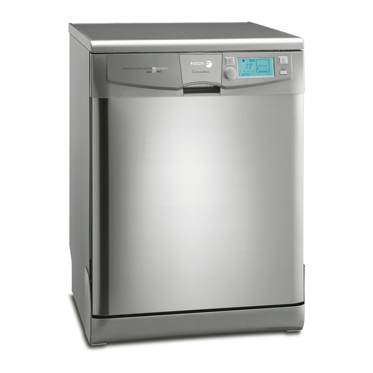
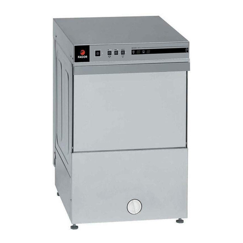
Fagor LVE-55 User manual

V28B001V2 / 2
Manuel d'installation de Lave-vaisselle
Manual de instalação màquinas de Lavar Louça
Dishwasher installation Manual
Installationshandbuch für Geschirrspülmaschinen
Manuale di installazione della lavastoviglie
Installatiehandleiding voor de vaatwasmachine
ENTUPO ODHGIWN EGKATASTASHS TOU PLUNTHRIOU PIATWN
Manual de instalación de lavavajillas

3
TABLE - INDICE - CONTENTS - INHALTSVERZEICHNIS - INDICE - INHOUD- PERIECOMENA-INDICE
FRANÇAIS
Description du manuel ......................................... 4
Déballaje ................................................................ 4
Lave-vaisselle indépendants ............................... 4
Lave-vaisselle habillables .................................... 4
Opérations pour l'habillage de la porte ............. 5
Lave-vaisselle encastrables ................................. 5
Habillage et ajustage de la porte ........................ 5
Lave-vaisselle intégrables ................................... 6
Opérations pour l'intégration du
lave-vaisselle ......................................................... 6
Raccordement au réseau d'eau ........................... 7
Raccordement de la vidange ............................... 7
Raccordement électrique ..................................... 8
PORTUGUÊS
Conselhos prévios ................................................ 9
Desenvalagem ....................................................... 9
Maquina de lavar louça independentes ............. 9
Maquinas de lavar louça painelaveis..................9
Decoração da porta ........................................... 10
Maquinas de lavar louça embutidas ................ 10
Colocação de painéis e regulação
da porta ............................................................... 10
Maquinas de lavar louça integráveis ............... 11
Operações para a integração da Maquina de
lavar louça ........................................................... 11
Ligação a rede de agua ..................................... 12
Conexão do esgoto ............................................ 13
Ligação eléctrica ................................................ 13
ENGLISH
Important information ........................................ 14
Unpacking ........................................................... 14
Free-standing dishwashers ............................... 14
Panellable dishwashers ..................................... 14
Fitting the panels ................................................ 15
Built-in dishwashers ........................................... 15
Panelling and adjusting the door ...................... 15
Integrated dishwashers ..................................... 16
Water supply connection .................................. 17
Drainage connection .......................................... 17
Electrical connections ........................................ 18
DEUTSCH
Einleitende Bemerkungen ................................ 19
Auspacken.......................................................... 19
Freistehender Geschirrspüler ......................... 19
Einpaßbarer Geschirrspüler ........................... 20
Arbeitsschritte zur Verkleidung der Tür ........ 20
Einklinkbarer Geschirrspüler .......................... 20
Arbeitsschritte zur Verkleidung der Tür ........ 21
Einsetzbarer Geschirrspüler ........................... 21
Auszuführende Arbeitsschritte zu
Einsetzen des Geschirrispülers ...................... 22
Wasseranschluß ................................................ 23
Wasserabfluß ..................................................... 23
Elektrische Anschlüsse ..................................... 24
ITALIANO
Avvertenze preliminari ......................................... 25
Disimballaggio ....................................................... 25
Lavastoviglie indipendenti ................................... 25
Lavastoviglie pannellabili ..................................... 25
Come pannellare la porta .................................... 26
Lavastoviglie a incasso ......................................... 26
Rivestimento della porta ....................................... 26
Lavastoviglie integrabili ....................................... 27
Come integrare la lavastoviglie .......................... 27
Allacciamento alla rete idrica .............................. 28
Allacciamento alla rete fognaria .......................... 28
Collegamenti elettrici ........................................... 29
NEDERLANDS:
Advies vooraf .................................................................. 30
Uitpakken ........................................................................ 30
Vrijstaande vaatwasmachines ...................................... 30
Tussenbouw vaatwasmachines .................................... 30
Decorpaneel van de deur ............................................. 31
Onderbouw vaatwasmaschines ................................... 31
Paneelbevestiging en afstelling van de deur .............. 31
Geintegreerde vaatwasmachines ................................ 32
Aanwijzingen voor het inbouwen van de
vaatwasmaschines ......................................................... 32
Wateraansluiting ............................................................. 33
Waterafvoer .................................................................... 34
Elektrische aansluitingen .............................................. 34
PERIECOMENA
Prokatarktik™j sust£seij ......................................... 35
ApÒsursh tou peritul… matoj ................................... 35
Plunt»ria pi£twn anex£rthta .................................. 35
Plunt»ria pi£twn ependuÒmena ............................... 35
En™r eiej ia thn ep™ndush thj pÒrtaj ............... 36
Plunt»ria pi£twn entoicizÒmena ............................ 36
Ep™ndush kai rÚqmish thj pÒrtaj ........................... 36
Plunt»ria pi£twn enswmatwnÒmena ...................... 37
En™r eiej ia thn enswm£twsh tou plunthr…ou37
SÚndesh sto d…ktuo neroÚ ............................................ 38
SÚndesh exa w »j neroÚ .............................................. 39
Hlektrik™j sund™seij ..................................................... 39
ESPAÑOL
Advertencias previas ............................................ 40
Desembalaje .......................................................... 40
Lavavajillas independientes ................................. 40
Lavavajillas panelables ......................................... 40
Operaciones para la panelación de la puerta .. 41
Lavavajillas encastrables ...................................... 41
Panelación y regulación de la puerta ................. 41
Lavavajillas integrables ........................................ 42
Operaciones para la integración del
lavavajillas .............................................................. 42
Conexión a la red de agua ................................... 43
Conexión de desagüe .......................................... 44
Conexiones eléctricas .......................................... 44

Description du manuel
Afin de faciliter au maximum les opèrations
d´installation du LAVE-VAISSELLE, nous
avons annexèàce MANUEL des pages fina-
les. Elles prèsentent, avec les dessins et les
croquis de l´appareil, une liste dètaillèe de
tous les èlèments ainsi que les mesures dont
il faudra tenir compte pour son installation.
Veuillez les dèplier, elle vous aideront à
mieux comprendre le texte ainsi qu´à rèsou-
dre les petits problèmes que vous pourriez
rencontrer.
Plaque des caractèristiques techniques
La PLAQUE DES CARACTERISTIQUES
TECHNIQUES se trouve sur le côtéde la
porte du LAVE-VAISSELLE. Les donnèes
techniques et d´identification de l´appareil y
figurent.
CONSULTEZ-LA avant de procèder aux
raccordements èlectriques.
Raccordements èlectriques
Les raccordements èlectriques doivent Ítre
effectuès par un spècialiste connaissant les
dispositions lègales et les exigences règle-
mentaires requises dans chaque pays.
Attention
Avant d´entreprendre l´installation de
l´appareil et d´effectuer les raccordements
èlectriquesetleraccordementde l´eau,ilest
très important de tenir compte des caractè-
ristiques du LAVE-VAISSELLE, ètant donnè
que s´il est HABILLABLE ou INTEGRABLE,
vousdevrezeffectuerunesèried´opèrations
prèalables pour assurer une installation
parfaite de l´appareil.
Dèballage
Retirez soigneusement tous les èlèments qui
protègent l´appareil.
Si votre lave-vaisselle est integrable, retirer
les cornières situés dans la partie inférieure
du Lave-vaisselle (Fig 2).
Retirez les èlèments de fixation des paniers.
Lave-vaisselle indèpendants
Introduction
Nos LAVE-VAISSELLE INDEPENDANTS ont
ètèconçus pour que vous puissiez les pla-
cer, isolès, àl´endroit le plus adèquat, en
fonction de vos besoins.
Dimensions
La Figure 2 donne les dimensions de
l´appareil. Consultez-la, cela vous facilitera
l´installation.
Mise à niveau et positionnement
Avant de procèder àl´installation du LAVE-
VAISSELLE, il est fondamental d´en règler
correctement l´assise au sol et la perpendi-
cularitè.
Mettez l´appareil àniveau en compensant
les èventuelles irrègularitès du sol.
Pour cela, règlez la hauteur des pieds situès
dans la partie infèrieure de l´appareil (Fig. 7)
(0 ÷20 mm).
L´inclinaison ne doit pas dèpasser 2%.
Après avoir effectuèces opèrations, procè-
dezauxraccordementsd´èlectricitèetd´eau
en suivant les instructions.
Lave-vaisselle habillables
Introduction
Nos LAVE-VAISSELLE HABILLABLES sont
conçus pour être placès soit sèparèment soit
au sein des autres meubles de votre cuisine;
dans ce cas, vous pourrez, en effectuant
quelques opèrations simples, l´adapter àla
dècoration et àla disposition du reste de
votre mobilier de cuisine.
Dimensions
La (Fig. 2) indique les dimensions de
l´appareil et la (Fig. 5) donne les dimensions
minimum du meuble.
Mise à niveau et positionnement
Avant de procèder àl´installation du LAVE-
FRANÇAIS
4
VAISSELLE, il est fondamental d´en règler
correctement l´assise au sol et la perpendi-
cularitè.
Mettez l´appareil àniveau en compensant
les èventuelles irrègularitès du sol.
Pour cela, règlez la hauteur des pieds situès
dans la partie infèrieure de l´appareil (Fig. 7)
(0 ÷20 mm).
L´inclinaison ne doit pas dèpasser 2%.
Dècoration de la porte
Afin que le LAVE-VAISSELLE ne brise pas
l´ambiancedècorativedevotrecuisine,vous
pouvez poser sur la porte, des revêtements
dècoratifs assortis au reste des meubles.
Ces revêtements peuvent avoir une èpais-
seur de jusqu´à 4,5 mm.
Opérations pour l'habillage de la porte
1.-Retirez le cadre de la porte du lave-vais-
selle après avoir défait les vis, comme
indiquéàla figure 3.
2.- Préparez le panneaux aux mesures indi-
quées àla figure 3 (597 x 587 mm.).
3.-Posez le panneau choisi et revissez le
cadre.
Une fois ces opérations terminées, effectuez
les raccordements d'électricitéet d'eau en
suivant les instructions.
Lave-vaisselle encastrables
Introduction
Nos LAVE-VAISSELLE ENCASTRABLES,
même s'ils peuvent être installés seuls, on
étéconçus pour que vous le placiez parmi
les meubles de votre cuisine, sous le plan de
travail. Pour cela, et grâce àune série d'opé-
rations simples, vous pouvez l'adapter àla
décoration des meubles et l'aligner sur les
portes du mobilier de votre cuisine.
Dimensions
La figure 5 indique les mesures de l'appareil
et les dimensions minimum du meuble; con-
sultez-les, cela vous facilitera les opérations.
Pour encastrer l´appareil sous un plan de
travail, démonter le plateau supérieur en
desserrant les deux vis de la figure 4 et retirer
égalementlecontre-poidsplacédans lapartie
supérieure de la machine (F ig.2).
Vous pouvez ensuite utiliser ces vis pour fixer
l'appareil au plan de travail et assurer la stabi-
litédu lave-vaisselle.
Mise àniveau et positionnement
Consultez le chapitre Mise àniveau et posi-
tionnement des Lave-vaisselle indépendants
et habillables.
Décoration de la porte
Afin que le LAVE-VAISSELLE ne brise pas
l'ambiance décorative de votre cuisine, vous
pouvez poser sur la porte, des revêtements
décoratifs assortis au reste des meubles.
Ces revêtements peuvent avoir une épais-
seur de jusqu'à4,5 mm.
Habillage et ajustage de la porte
1.- Retirez le cadre de la porte du lave-vaisse-
lle après avoir dèfait les vis, comme indi-
quèàla figure 6.
2.-Dècoupez le panneau dècoratif en fonction
de la hauteur (h) nècessaire pour l´aligner
sur les armoires voisines.
3.-Prèparez le cadre de la porte et raccour-
cissez en les sciant les extrèmitès supè-
rieures àla même hauteur (h) que le pan-
neau dècoratif.
4.-Ajustez àla hauteur (h) le supplèment infè-
rieur de la porte.
5.-Posez le panneau dècoratif sur la porte et
fixez le cadre, puis marquez ànouveau la
position des nouveaux trous sur la porte,
percez avec une mêche de Ø3,25 mm et
revissez le cadre.
Remarque
Si le lave-vaisselle va être encastrèdans une
FRANÇAIS
5

rangèe de meubles de cuisine àplinthe uni-
que,cetteoptionestpossiblemaisil faut tenir
compte de:
1.-Retirez la plinthe (1) et les supports pieds
(2) après avoir dèfait les vis (comme indi-
quèàla Fig. 1).
2.-N´oubliez pas de passer les pieds règla-
bles de la Position A àla Position B.
3.-Posez la plinthe du meuble de cuisine
après l´avoir dècoupèe àla mesure sou-
haitèe (comme indiquèàla Fig. 4).
Une fois ces opèrations faites, effectuez les
raccordements d´èlectricitèet d´eau en sui-
vant les instructions.
Lave-vaisselle intègrables
Nos LAVE-VAISSELLE INTEGRABLES sont
conçus pour que le revêtement de la porte et
dubandeaudecommandes coïncide avec la
forme et les dimensions d´un module de
cuisinede60 cm delarge, avec porte ettiroir
dans la partie supèrieure.
Pour cela, vous devrez effectuer les opèra-
tions suivantes:
Dimensions
LaFigure5 indiquelesmesuresdel´appareil
et les dimensions minimum du meuble; con-
sultez-la, cela vous facilitera les opèrations.
Si votre lave-vaisselle est integrable, retirer
les cornières situés dans la partie inférieure
du Lave-vaisselle (Fig 2).
Mise àniveau et positionnement
Consultez le chapitre Mise àNiveau et Posi-
tionnementdesLave-vaisselle indèpendants
et habillables.
Opèrations pour l´intègration
du lave-vaisselle
Règlage en hauteur du lave-vaisselle
Faites tourner les pieds B du lave-vaisselle
dans le sens contraire de celui des aiguilles
d´une montre jusqu´à ce que la partie supè-
rieure de l´appareil entre en contact avec la
partie infèrieure du plan de travail du meu-
ble de cuisine (Fig. 7).
De cette façon on peut régler le LAVE-
VAISELLE jusqu'à870 mm. en hauteur.
Calage du bandeau de commandes
(Fig. 8)
Cette opèration consiste àcaler le Bandeau
de Commandes du Lave-vaisselle jusqu´à
ce que sa hauteur s´aligne sur celle du pan-
neau du tiroir du meuble de cuisine.
Pour effectuer cette opèration, utilisez les
règlettes et les vis livrèes àl´intèrieur de
l´appareil.
Si la hauteur du panneau du tiroir est de 110
mm, aucun calage n´est nècessaire.
Si la hauteur est supèrieure, ajoutez des
règlettes (cale A = 5 mm; cale B = 10 mm) de
manière àavoir des modules de 5 mm et
ajustez au niveau des tiroirs des meubles
voisins (Fig. 8).
Une fois ces opèrations effectuèes, il faudra
tenir compte du fait que, lorsque vous pose-
rez le Revêtement Porte, la partie infèrieure
de ce dernier doit se trouver au ras de la
plinthe des meubles de cuisine.
Intègration du lave-vaisselle
Les opèrations et vèrifications prècèdentes
ètant terminèes, procèdez àl´intègration du
lave-vaisselle. Pour ce faire, effectuez les
opèrations suivantes:
1.- Mettez en place la protection en plastique
duplandetravaildumeuble,fournieavec
l´appareil (Fig. 9).
Cette protection empêchera que les
buèes produites par le lave-vaisselle
n´endommagent la partie intèrieure du
plan de travail du meuble de cuisine.
2.- A l´aide du gabarit fourni avec l´appareil,
marquez au dos du RevÍtement-Panneau
les points oùseront placès les supports
de fixation au lave-vaisselle (Fig. 10).
FRANÇAIS
6

N.B.:
Lors de la pose du revêtement de façade, il
faut tenir du calage ou non du Bandeau de
Commandes du Lave-vaisselle avec des rè-
glettes.
A) S´il n´y a pas de calage, faites coïncider la
rèfèrence 0 du bord du gabarit avec le
bord supèrieur du RevÍtement-Porte.
B) Si, au contraire, vous avez calèle Ban-
deau de Commandes, faites coïncider les
rèfèrences marquèes sur le gabarit (de 5
mm) en fonction du nombre de règlettes
misesenplace,aveclebordsupèrieurdu
Revêtement-Porte.
3.-Placez le gabarit en le maintenant et mar-
quez la position des trous. Percez ensuite
les trous avec une mèche de 2,5 mm et
vissezlessupports aurevêtementenvous
assurant que la partie courbe du support
est orientèe vers le haut (bord Y, Fig. 11).
Attention! Limitez la profondeur des
trous.
4.-Prenez le Revêtement-Porte en orientant
le bord (Y) vers le haut puis introduisez
les supports dans le logement dont dispo-
se la porte. Tirez alors le revêtement vers
le haut jusqu´à ce qu´il touche le bandeau
de commandes et assurez-vous que tous
les supports sont bien fixès dans les loge-
ments de la porte (Fig. 12).
5.-Ouvrez lentement la porte du lave-vais-
selle tout en maintenant le revêtement
puis fixez ce dernier àl´aide des vis four-
niesen veillant àl´alignement du panneau
par rapport àla porte (Fig. 13).
N.B.:
Pour adapter le lave-vaisselle àune rangèe
de meubles de cuisine àplinthe unique,
effectuez les opèrations suivantes:
6.-Mettez en place la plinthe du meuble de
cuisineaprès l´avoir dècoupèeàla mesu-
re souhaitèe (Fig. 4).
7.-Fixation du plan de travail (Fig. 14)
8.- Vèrification du fonctionnement (Fig. 15).
Lorsque ces pièces sont fixèes au lave-vaisse-
lle, celui-ci est prêt pour son intègration dèfi-
nitive.
Une fois ces opèrations faites, effectuez les
raccordements d´èlectricitèet d´eau,en sui-
vant les instructions.
Ces figures peuvent ègalement être consul-
tèes sur le gabarit fourni avec l´appareil.
Raccordement au rèseau d´eau
Pour raccorder le LAVE-VAISSELLE au rè-
seau d´eau, il faut utiliser le TUYAU
D´ALIMENTATION fourni avec la machine et
lebrancheràunrobinet d´eau ayantunesortie
filetèe R 3/4”. (Fig. 16).
La pression de fonctionnement doit être com-
prise entre 4,9 et 98 N/cm2. Si la pression est
plus importante, posez une vanne de rèduc-
tion de pression, que vous trouverez dans le
commerce.
Très important
Le tuyau d´arrivèe d´eau ne doit être ni plièni
ètranglècar cela pourrait empêcher le rem-
plissage du lave-vaisselle.
Entrèe d´eau chaude
Bien qu´il soit prèfèrable de raccorder
l´appareil àl´eau froide, certains modèles
peuventêtreraccordèsindistinctementàl´eau
froide ou l´eau chaude (maxi. 60°C). Dans ce
cas, consultez votre revendeur.
Raccordement de la vidange
Le RACCORDEMENT DE LA VIDANGE se fait
àl´aide d´un tuyau coudèremplissant les con-
ditions suivantes:
1.-La longueur du tuyau doit être infèrieure à
3 mètres.
2.-L´extrèmitèdu tuyau de vidange doit se
trouver àune hauteur entre 0,5 m et 1 m du
sol (Fig. 17).
3.- Il est nècessaire de poser un siphon pour
èviter toute remontèe d´odeurs par le con-
duit de vidange.
4.-Evitez les coudes et ètranglements qui
empêchent la libre èvacuation de l´eau.
FRANÇAIS
7

Très important
Après avoir effectuèle raccordement, assu-
rez-vous que le coude du tuyau est bien fixè
àla sortie afin d´èviter les fuites d´eau et le
risque d´une èventuelles inondation.
Raccordement èlectrique
NosLAVE-VAISSELLEpeuventsupporterune
intensitèmaximum de 16 A. LA PRISE DE
TERRE EST DONC INDISPENSABLE.
Le FIL D´ALIMENTATION de la machine est
dotèd´une mise àla terre qu´il est nécessai-
re de raccorder àune prise assurant la con-
tinuitéàla terre.
Avantdebrancherlamachine,ilfauts´assurer
que la tension du domicile coïncide avec la
tension de fonctionnement du LAVE-VAIS-
SELLE.
FRANÇAIS
8
Ce renseignement apparaît sur la PLAQUE
DE CARACTERISTIQUES située sur le côté
de la porte du Lave-vaisselle.
Silecâbled’alimentation estendommagé,
il doit être remplacé. Le fabricant, un
membre de son Service Technique ou de
son personnel agréé sont les seuls à
pouvoir procéder àsa substitution.
LE FABRICANT DECLINE TOUTE RESPON-
SABILITE EN CAS DE NON OBSERVATION
DE CES NORMES.
Ce lave-vaisselle remplit les dispositions de
la Directive Europèenne 87/308/CEE con-
cernant les perturbations radioèlectriques.

PORTUGUÊS
Conselhos prévios
Descrição do manual
Para facilitar ao máximo os trabalhos e insta-
lação da sua MAQUINA DE LAVAR LOUÇA
anexa-se a este MANUAL umas paginas fi-
nais.
Nelas aparece junto com os desenhos e es-
quemas da maquina, uma relação detalhada
de todos aqueles elementos, bem como
medidas e operações que deverão ser to-
madas em conta na hora da sua instalação.
Consulte-as pois poderão ser de ajuda a
hora da inalação assim como para resolver
pequenos e eventuais problemas que po-
dam aparecer.
Placa de Características Técnicas
Situada no lateral da porta da maquina de
lavar louça encontrasse a PLACA DE CA-
RACTERISTICAS TÉCNICAS . Nela figuram
os dados técnicos e de identificação da
maquina.
CONSULTE-A Antes de fazer as ligações
eléctricas.
Ligações eléctricas
As ligações eléctricas devem ser feitas por
um especialista que esteja ao corrente das
disposições legais e das exigências norma-
tivas reconhecidas em cada pais.
Atenção
Antes de proceder a instalação da maquina
e fazer as ligações eléctricas como as de
agua e muito importante que tenha em conta
as características da sua MAQUINA DE LA-
VAR LOUÇA, visto se for PAINELAVEL ou
INTEGRAVEL, devera realizar uma serie de
operações previas a fim de conseguir uma
instalação perfeita.
Desenvalagem
Retire com cuidado todos os elementos que
protegem a maquina. Se o seu lava-louça é
integrável retire os esquadros situados na
parte inferior de lava-louça. (Fig. 2).
Retire os elementos de fixação dos cestos.
Maquina de lavar louça
independentes
Introdução
As nossas MAQUINAS DE LAVAR LOUÇA IN-
DEPENDENTES foram criadas para poderem
ser colocadas isoladamente no lugar mais
adequado de acordo com as suas necessida-
des.
Dimensões
Na figura 2 dão se as medidas da maquina.
Consulte-as pois elas facilitaram-lhe a sua in-
stalação.
Nivelamento e colocação
Antes de proceder a instalação da maquina e
importante conseguir uma boa estabilidade
doaparelhonochão,bemcomo a suaperpen-
dicularidade.
Por isso nivele a para corrigir possíveis irre-
gularidade do chão. Para isso regule a altura
dos pés situados na parte inferior da maquina
( Fig. 7) (0+20mm)
A inclinação permitida e de 2%.
Depois de corrigidas estas irregularidade
efectueasligações eléctrica ede agua confor-
me as instruções.
Maquinas de lavar louça
painelaveis
Introdução
As nossas MAQUINAS DE LAVAR LOUÇA
PAINELAVEIS estão desenhadas para que as
possa colocar tanto isoladamente como entre
o resto dos moveis da cozinha: Neste caso
poderá, realizando umas operações simples,
adaptada a decoração e disposição do resto
do miviliario da cozinha.
Dimensões
Na figura 2 estão especificadas as medidas da
9

maquina e na figura 5 as mínimas do móvel.
Nivelamento e colocacão
Antes de proceder a instalação da maquina
e importante conseguir uma boa estabilida-
de do aparelho no chão, bem como a sua
perpendicularidade.
Por isso nivele-a para corrigir possíveis irre-
gularidade do chão. Para isso regule a altura
dos pés situados na parte inferior da maqui-
na ( Fig. 7) (0+20mm)
A inclinação permitida e de 2%.
Decoração da porta
Para que a MAQUINA DE LAVAR LOUÇA
combine com o ambiente decorativo da sua
cozinha vocêpode colocar encima da porta
revestimentosdecorativoscombinados com
o esto dos moveis. Estes revestimentos de-
corativos sópodem ter uma grossura máxi-
ma de 4,5mm
Operações para colocar os revesti-
mentos da porta
1.-Retire a moldura da prata da maquina de
lavar louça soltando os parafusos (figura
3)
2.-Prepare os painéis com as medidas indi-
cados na figura 3 (597x587 mm).
3.-Coloque os painéis que vocêescolheu e
volte a aparafusar as molduras.
Depois de realizar estas operações realize
as ligações eléctricas e de agua conforme as
instruções.
Maquinas de lavar louça em-
butidas
Introdução
As nossas maquinas de lavar louça embuti-
das também podem ser colocadas isolada-
mente mas estão pensadas para que vocêas
coloque entre os moveis da sua cozinha
debaixo do encimado. Realizando para isso
uma serie de operações vocêpoderáadap-
tar a sua maquina a decoração do móvel e
conseguir um alinhamento com as portas do
mobiliaria da sua cozinha.
Dimensões
Na figura 5 aparecem as dimensões do
aparelhoeasmínimas do móvel,consulteas,
facilitar Ihe áas operações.
Se quiser colocar por baixo do balcão da
cozinha deve desmontar a mesa superior
desapertando os dois parafusos da figura 4
e, para além disso, retirar o contrapeso si-
tuado na parte superior da máquina. (Fif. 2).
Posteriormente poderáutilizar estes parafu-
sos para a fixação da maquina com o enci-
mado e garantir assim uma estabilidade da
maquina de lavar louça.
Nivelação e posicionamento
Consulte linha Nivelação e posicionamento
maquinas de lavar louça independentes e
com paneis.
Decoração da porta
Para que a maquina de lavar louça combine
com o ambiente decorativo da sua cozinha
vocêpode colocar encima da porta revesti-
mentos . Sópodem ter uma grossura máxi-
ma de 4,5 mm.
Colocação de painéis e regulação da
porta
1.- Retire a moldura da porta da maquina de
lavar louça soltando os parafusos (Fig. 6)
2.-Cortar o painel decorativo de acordo a
altura que for necessária (h) para um
alinhamento com os moveis contíguos.
3.- Serrar os extremos superiores da moldu-
ra da porta, a idêntica altura (h) que o
painel decorativo.
4.- Ajustar áaltura (h) o suplemento inferior
da porta.
5.-Coloque o painel decorativo na porta
segure ao mesmo tempo o quadro e volte
a marcar a posição dos novos buracos na
porta e fazer os com uma broca de 3,25
mm e volte a aparafusar o quadro.
PORTUGUÊS
10

Observação:
No caso de encaixar a maquina de lavar
louça numa fila de moveis de cozinha com
um painel de rodapéexiste esta opção mas
lembrasse do seguinte:
1.-Retire a base do rodapé(1) e os soportes
das patas (2) soltando os parafusos (fig.1)
2.- Não se esqueça de mudar as patas regu-
láveis da posição A posição B.
3.-Encaixar o rodapéda cozinha serrando
ate conseguir a medida desejada (Fig. 4).
Depois de fazer as operações proceda a
realizar as conexões eléctricas e de agua
conforme as instruções.
Maquinas de lavar louça inte-
gráveis
Introdução
As nossas MAQUINAS DE LAVAR LOUÇA
INTEGRAVEIS,estão desenhadas para que o
revestimento da porta e painel de comandos
coincida com a forma e dimensões de um
modulo de cozinha de 60 cm de largura com
a porta e gaveta na parte superior. Para
conseguir isso vocêdevera realizar as se-
guintes operações:
Dimensões
Na figura 5 aparecem as dimensões do apa-
relho e as mínimas do móvel, consulte-as,
facilitar-lhe-áas operações.
Recuerde que seu lava-louça éintegrável
retire os esquadros situados na parte inferior
de lava-louça. (Fig. 2).
Nivelação e posicionamento
Consulte linha Nivelação e posicionamento
maquinas de lavar louça independentes e
com paneis.
Operasões para a integração
da Maquina de lavar louça
Regulação da altura da maquina de
lavar louça
Virar os pés do lava-loiça no sentido anti
horário, atéa parte superior do aparelho to-
marcontacto com o plano inferior do móvel da
cozinha (fig. 7).
Desta maneira o lava-loiça fica instalado par
poder conseguir regulá-lo até870 mm.
Calçamento do painel de comandos
(Fig. 8)
Esta operação consiste em calçar o painel de
comandos da maquina de lavar louça ate que
a sua altura seja igual a do painel da gaveta do
móvel da cozinha.
Para realizar esta operação utilize as réguas e
parafusos que são fornecidos no interior do
aparelho.
Se a altura do painel da gaveta for de 110 mm
não e preciso nenhum calçamento. Se a altura
forsuperioracrescenteasréguasnecessárias
( calço A = 5 mm, calço B = 10 mm ) construin-
do módulos de 5 mm ajustando ao nível das
gavetas dos moveis contíguos (Fig. 8).
Depois de realizar estas operações vocêtem
de ter em conta que quando coloque o reves-
timento porta na parte inferior tem de ficar
nivelada com o rodapédos moveis da sua
cozinha.
Integração da Maquina de lavar louça
Depois de realizar e comprovar as anteriores
operações proceda a integração da Maquina
de lavar louça para isso proceda da seguinte
forma:
1. Coloque a protecção em plástico do enci-
mado do móvel que se fornece com o
aparelho (fig. 9)
Esta protecção evitara que os gases forma-
PORTUGUÊS
11

dos ao funcionar a maquina de lavar lou-
ça incidam na parte interior do encimado
do móvel da cozinha.
2. Com ajuda do molde fornecido com o
aparelho marque no dorso do revesti-
mento-porta os pontos onde mais tarde
vai a montar as peças de união com as do
as do aparelho (fig.10)
Observação
No momento de fazer o revestimento frontal
vocêdeve saber se fez o calçamento do
porta-comandos com as réguas .
A) Se vocênão fez o calçamento, faça coin-
cidir a referencia O situada na beira su-
perior do molde com a beira superior do
revestimento porta.
B) Se vocêjátinha feito o calçamento do
porta-comandos da maquina de lavar
louça faça coincidir as referencias mar-
cadasno molde de (5 mm)com o numero
de réguas que colocou na beira superior
do revestimento porta.
3.- Por o molde de forma horizontal, segurar
e marcar os pontos desejados ( fig. 10 )
seguidamente com uma broca de 2,5
mm realizar os furos correspondentes e
agarrar as peças de união com o tabulei-
ro revestimento (Fig. 11)
Cuidado: limitar a profundidade da bro-
ca.
4. Agarre o revestimento porta da beira (y)
para cima e seguidamente encaixe os
soportes nos alojamentos que a porta
tem. Então suba o revestimento ate con-
tactar com o painel de comandos, asse-
gurando-sequetodosossoportesficaram
bem fixados nos alojamentos da porta
(Fig. 12).
5. Abrir lentamente a porta da maquina de
deixando descender ao mesmo tempo o
revestimento,nivelarassentarcomaporta
da maquina de lavar louça, fixar o reves-
timento a porta aparafusando com os
parafusos que se fornecem (Fig. 13)
Observação:
Para adaptar a maquina de lavar louça inte-
grável com uma fila de moveis de cozinha
com um painel de rodapéúnico realize as
seguintes operações:
6.-Encaixar o rodapédo móvel da cozinha
serrando ate conseguir a medida deseja-
da ( Fig. 4)
7.- Fixação ao encimado (fig. 14)
8.- Comprovação do funcionamento (fig. 15)
Quando estas peças estejam ajustadas a
maquina de lavar lou,ca esta preparada
para a integração definitiva.
Depois de realizar estas operações proceda
a realizar as conexões eléctricas e de agua
conforme as instruções.
Estas figuras também podem ser consulta-
das no molde que se fornece com o aparel-
ho.
Ligação a rede de agua
Para ligar a MAQUINA DE LAVAR LOUÇA a
rededeaguadeveráusaraMANGUEIRADE
PRESSAO fornecida com a maquina, numa
torneira com uma boca de rosca R3/4" (fig.
16).
A pressão de funcionamento deve ser entre
4,9 a 98 n/cm2. No caso de ser maior devese
colocar uma válvula de redução de pressão
que poderáadquirir numa loja da especiali-
dade.
Muito importante
A mangueira de entrada da agua deve ser
colocada sem dobras nem estrangulamen-
tos que impeçam a entrada livre de agua na
maquina de lavar louça.
Entrada de agua quente
A pesar de que e preferível conectar na
entrada de agua fria alguns modelos podem
ser conectados tanto a agua fria como a
quente (max. 60 °C).
Consulte no seu comercio.
PORTUGUÊS
12

Conexão do esgoto
A Ligacão DO ESGOTO e efectuada a traves
de uma mangueira em forma de cotovelo
com as seguintes condições:
1°Ocomprimentodamangueira devera ser
inferior a 3 metros.
2°A extremidade do tubo do esgotamento
de ficar a uma altura entre 0,5 e 1 m em
relação ao chão (fig17).
3°E necessário a colocação de um sifão
para que o esgotamento seja inodora.
4°Evite dobras e estrangulamentos que não
deixem sair a agua livremente.
Muito importante
Depois de efectuada a ligação, verifique se o
cotovelo esta convenientemente fixado a
saída, a fim de evitar fugas e o consequente
risco de inundação.
Ligação eléctrica
As nossas maquinas podem suportar uma
intensidade máxima de 16 A SENDO IM-
PORTUGUÊS
13
PRESCINDIVEL A TOMA DE TERRA. O FIO DE
ALIMENTACAO Da maquina dispõe de terra
sendo necessário ligado a uma boa toma a
traves da qual fique garantida a continuidade
da terra.
Antes de ligar a ficha de toma de corrente é
necessário certificar-se que a tensão da sua
casa coincida com a tensão de funcionamento
da maquina .
Este dado encontra-se na PLACA DAS CA-
RACTERÍSTICAS situada no lateral da porta
da máquina de lavar loiça.
Se o cabo de alimentação resultar avariado,
devesersubstituído.Asubstituiçãosópode
ser realizada pelo fabricante, pelo seu
Serviço Técnico ou pelo pessoal autoriza-
do.
O FABRICANTE DECLINA TODA RESPONSA-
BILIDADE EM CASO DE QUE ESTAS NOR-
MAS NAO SEJAM OBSERVADAS.
Esta maquina de lavar louça cumpre os requi-
sitos da Directiva Europeia 87/308/CEE sobre
as perturbações radioelectricas.

ENGLISH
Free-standing dishwashers
Introduction
Our FREE-STANDING DISHWASHERS have
been designed so taht you can put them on
their own, in the most suitable spot.
Dimensions
Figure 2 gives the measurements of the
appliance. Study them, as they will help you
install the appliance.
Levelling and positioning
Before installing the DISHWASHER, the ap-
pliance must stand firmly on the floor and be
as perpendicular as possible.
Level it accordngly. correcting any possible
irregularities in the floor.
This may be done by adjusting the height of
thefeetat the bottom oftheappliance (Figure
7) (0-20 mm).
A maximum 2% inclination level is allowed.
Once you have completed these
tasks, proceed with the electrical and
water connections according to the
instructions.
Panellable dishwashers
Introduction
Our PANELLABLE DISHWASHERS are de-
signed so that you can put them on their own
or in with the rest of your kitchen cabinets
and appliances. In the latter case, you can
adapt them to the decor and arangement of
your kitchen, by performing a few simple
operations.
Dimensions
Figure 2 provides the measurements of the
appliance and Figure 5 the minimum measu-
rements of the kitchen units.
Levelling and positioning
Before installing the DISHWASHER, the ap-
Important information
In order to help install your DISHWASHER,
we have included a series of drawings and
diagrams at the end of this MANUAL..
They also provide a detailed list of all the
elements, measurements and operations to
keep in mind during installation.
Please open out the drawings and diagrams,
as they will help you to understand the text
and be a great help in solving small proble-
mas when installing the dishwasher.
Technical Specification Plate
The TECHNICAL SPECIFICATIONS PLATE,
stuck on the side of the DISHWASHER door,
contains technical information as well as the
serial number of the appliance.
READ THIS INFORMATION before making
the electrical connections.
Electrical Connections
Theelectrical connectionsshould be carried
out by a specialist who is familiar with the
legal provisions as wellasthe standards and
regulations in force in each country.
Warning
Before installing the appliance and connec-
tingboth the water and electricity supply, it is
extremely important that you take into ac-
count whether your DISHWASHER is a PA-
NELLABLE or INTEGRATED model. You will
need to perform a number of operations to
ensure that you isr installed dishwasher pro-
perl.
Unpacking
Carefully remove all the protective packing
from the appliance.
If your dishwasher is an integrated model,
remove the brackets located at the bottom of
the dishwasher. (Fig. 2).
Remove the packing from around the bas-
kets inside the machine.
14

ENGLISH
pliance must stand firmly on the floor and be
as perpendicular as possible.
Level it accordngly. correcting any possible
irregularities in the floor.
This may be done by adjusting the height of
thefeetat the bottom oftheappliance (Figure
7) (0-20 mm).
A maximum 2% inclination level is allowed.
Door decoration
You can fit decorative panels to the door of
your DISHWASHER so that it matches the
surrounding decor.
This pannelling may be up to 4.5 mm thick.
Fitting the panels
1.-Remove the door frame from your dish-
washer by undoing the screws as shown
in Figure 3.
2.-Prepare the panel according to the mea-
surements given in Figure 3 (597 x 587
mm).
3.-Fit the panel you have chosen and screw
the frame back into place.
Once you have done this, proceed
with the water and electricity
supply connections according to the
instructions.
Built-in dishwashers
Introduction
Although they can also be used as free-
standingappliances,ourBUILT-INDISHWAS-
HERS are designed so that you can fit them
into your kitchen under the work surface.
You may easily adapt your dishwasher to the
decor and door alignment of the rest of your
kitchen by performing a few simple opera-
tions.
Dimensions
Figure 5 gives the measurements of your
dishwasher and the minimum requirements
for the kitchen units. These will help you in
the installation process.
If you want to put your dishwasher under the
kitchen work surface, you have to remove the
top cover by undoing the two screws shown in
Figure 4 and also remove the counter weight
located at the top of the machine. (Fig. 2)
You can use these same screws later to secure
your appliance to the kitchen work surface,
thereby ensuring the stability of the dishwas-
her.
Levelling and positioning
Refer to the section on levelling and positio-
ning for free-standing and panellable
dishwashers.
Door decoration
You can fit decorative panels to the door of
your DISHWASHER so that it matches the su-
rrounding decor.
This panneling may be up to 4.5 mm thick.
Panelling and adjusting the door
1.-Remove the door frame form your dish-
washer by undoing the screws as shwon in
Figure 6.
2.-Cut the decorative panel according to the
height required (h) to line it up with the
kitchen units either side.
3.-Takethedoorframeandcutit,bysawing off
the top ends, to the same height (h) as the
decorative panel.
4.-Adjust the lower door shim to the right
height (h).
5.-Fit the decorative panel to the door. At the
same time secure the frame and re-mark
the position of the new holes in the door.
Make the holes with a 3.25 mm drill bit.
Screw the frame back into place.
Note
If you want to fit your dishwasher into a row of
kitchen units with a single kickstrip, this is
possible, although you should bear the follo-
wing in mind:
1.-Remove the base (1) and the feet (2) by un-
doing the screws (according to Figure 1).
15

2.-Donotforget to change the adjustable feet
from Position A to Position B.
3.-Fit the kitchen unit kickstrip, sawing it to
the size required (according to Figure 4).
Once you have completed these tasks,
proceed with the electrical and
water connections according to the
instructions.
Integrated dishwashers
Introduction
Our INTEGRATED DISHWASHERS are de-
signed so that the door covering and the
control panel match the shape and size of 60
cm wide kitchen modules with a door and a
drawer at the top.
To do this, proceed as follows:
Dimensions
Figure 5 gives the measurements of your
dishwasher and the minimum requirements
for the kitchen units. These will help you in
the installation process
And remember if your dishwasher is an
integrated model, remove the brackets
located at the bottom of the dishwasher.
(Fig. 2).
Levelling and positioning
Refer to the section on levelling and positio-
ning for free-standing and panellable
dishwashers.
Integrating your dishwasher
Adjusting the height of the dishwasher
Turn the dishwasher feet B anticlockwise,
until the tp of the appliance comes into con-
tact wit the bottom of the kitchen work surfa-
ce (Figure 7).
This enables the DISHWASHER height to be
adjusted up to 870 mm.
Aligning the control panel (Figure 8)
Thisoperationconsistsofaligning thecontrol
panel of the dishwasher until it is at the same
height as the drawer panels of your kitchen
units.
Usethespacingpiecesandscrewsprovided
inside the appliance to carry out this opera-
tion.
If the height of the drawer panel is 110 mm, it
is not necessary to make any adjustments.
If it is higher, add as many spacing pieces as
necessary (spacer A = 5 mm, spacer B = 10
mm), forming 5 mm modules, to adjust the
height of the control panel to that of the
drawer panels of adjacent units (Figure 8).
Once you have done this, bear in mind that
when you fit the door panel, the bottom of it
must be in line with the kickplate of your
kitchen units.
Integrating your dishwasher
Onceyou have carried out the previous ope-
rations, proceed with the integration of your
dishwasher, as follows:
1.-Fit the protective plastic cover supplied
with the appliance to the underside of
your kitchen work surface (Figure 9).
This cover will prevent the condensation
generated during the operation of your
dishwasher from damaging the undersi-
de of your work surface.
2.-Using the template supplied with your
appliance,markthepointswherethebrac-
kets for fixing to the dishwasher are to go
on the back of the door panel (Figure 10).
Note
When preparing the front panel you must
take into account whetehr or not you have
increased the height of the control panel with
spacing pieces.
A) If you have not, align reference point 0,
located on the top edge of the template,
with the top edge of the door panel.
ENGLISH
16

B) If,however,youhaveincreasedtheheight
of the control panel, match the reference
points marked on the template every 5
mm with the number of spacing pieces
fitted to the top edge of the door panel.
3.-Fit the template,secureit and mark thethe
position of the holes. The drill them with a
2.5 mm drill bit and screw the brackets to
the panel, ensuring that the curved part of
thebrackettfaces upwards (edge Y,Figu-
re 11):
Take care not to drill too deeply.
4.-Take the door panel, with the edge (Y)
facng upwards and fit the brackets in the
slots in the door. Then pull the panel up
until it touches the control panel, ensuring
that all the brackets are properly secured
in the slots in the door (Figure 12).
5.-Slowly open the dishwasher door, hol-
ding the panel at the same time. Then
screw it tight using the screws supplied,
ensuring that it is properly aligned with
the door (Figure 13).
Note
To fit your integrated dishwasher into a row
of kitchen units with a continuous kickstrip,
proceed as follows:
6.-Fit the kickstrip, sawing it to the right size
(Figure 4)
7.-Secure the dishwasher to the work surfa-
ce (Figure 14)
8.-Check that the door opens and closes
properly (Figure 15).
When these parts have been fitted, the dish-
washer is ready for integration.
Once these operations have been carried
out, proceed to connect the electricity
and water supplies according to the
instructions.
These figures can also be consulted on the
template supplied with the appliance.
Water supply connection
To connect the DISHWASHER to the mains
water supply, use the PRESSURE HOSE sup-
plied with the machine. Join it to a water tap
with a R 3/4”threaded mouth (Fig. 16).
The operating pressure should be between
4.9 - 98 N/cm2. If it is higher, connect a pressu-
re reducer valve, which you can buy in a shop
selling plumbing supplies.
Very important
The water inlet hose should not have any kinks
in it which might prevent the free entry of
water into the DISHWASHER.
Hot water inlet
Although it is best to connect the machine to
the cold water supply, some models can be
connectedtoeitherthecoldorhotwatersupply
(max. 60°C). Enquire at your local dealer.
Drainage connection
The DRAINAGE CONNECTION is made with
a kneed hose that meets the following require-
ments:
1.-Less than 3 metres long.
2.-The end of the drainage pipe should be at
a height of between 0.5m and 1m from the
floor (Figure 17).
3.-A sump needs to be fitted for odour-free
drainage.
4.-Avoid kinks which prevent the water from
flowing out freely.
Very important
When you have completed the connection,
ensure that the pipe elbow is well anchored to
the outlet. This will avoid water leaks and the
risk of floods.
ENGLISH
17

Electrical connection
Our DISHWASHERS can withstand a maxi-
mun intensity of 16A. THE APPLIANCE MUST
BE EARTHED.
The POWER CABLE supplied with teh ma-
chine has an earth terminal, which must be
connected to a proper socket to guarantee
the earth connection.
Before plugging the appliance in, check that
yourelectricitysupplyvoltagecoincideswith
the operating voltage of your DISWASHER.
This information is given on the
ENGLISH
18
CHARACTERISTICS PLAQUE located on the
side of the Dishwasher door.
If the power cord is damaged, it must be
replaced. It can only be replaced by the
manufacturer,anauthorizedservicecentre
or authorized service engineers.
THE MANUFACTURER CANNOT ACCEPT
ANY RESPONSIBILITY IF THESE INSTRUC-
TIONS ARE NOT FOLLOWED.
This dishwasher complies with the provi-
sionsofEuropeanDirective87/308/EECcon-
cerning radio interference.

DEUTSCH
Einleitende Bemerkungen
Beschreibung des vorliegenden
Handbuchs
Um die Installationsarbeiten Ihres neuen
GESCHIRRSPÜLERS weitgehend zu verein-
fachen, haben wir diesem Handbuch einige
Extraseiten über die Installation angefügt.
Auf diesen Seiten finden Sie mehrere Abbil-
dungenundZeichnungendesGerätes,sowie
einegenaueAufstellungallerzumGeschirrs-
püler gehörenden Bauteile. Desweiteren
finden Sie hier eine Beschreibung der bei
der Installation zu berücksichtigenden
Maßnahmen und Arbeitsschritte.
Wir empfehlen Ihnen, die bebilderten Seiten
aufzuklappen, um sich mit Ihrem Geschirrs-
püler vertraut zu machen. Die Abbildungen
erleichtern Ihnen das Verstehen des Textes
und werden Ihnen bei der Lösung kleinerer
Fehler und Pannen, die eventuell auftreten
können, behilflich sein.
Typenschild
An der Innenseite der GERÄTETÜR befindet
sich das TYPENSCHILD, auf dem alle Leis-
tungsdaten und Kennzeichnungen des Ge-
schirrspülers angegeben sind.
Bevor zum Anschlußdes Gerätes überge-
gangen wird, mußsichergestellt sein, daß
die Netzspannung mit der Gerätespannung
übereinstimmt. Hierzu sehen Sie bitte auf
dem Typenschild nach.
Elektrischer Anschluß
Der elektrische Anschlußdarf nur von ei-
gens hierzu qualifiziertem Fachpersonal
vorgenommenwerden,welchesgenauüber
die jeweils gültigen Bestimmungen und Ver-
ordnungen im Bilde ist.
Wichtig
Je nach Geräteart Ihres Geschirrspülers
(FREISTEHEND oder EINBAUBAR) sind für
die ordnungsgemäße Aufstellung verschie-
deneVorbereitungsarbeitendurchzuführen,
bevor die Installation, der elektrische Ansch-
lußsowie der Wasseranschlußvorgenom-
men werden können.
Auspacken
Entfernen Sie zunächst vorsichtig alle Verpac-
kungselemente, die den Geschirrspüler wäh-
rend des Transports vor Beschädigungen
schützen.
Sollte es sich um eine einhaubare
Spülmaschine handeln, entfernen Sie bitte die
Winkel am unteren Teil der Spülmaschine.
(Abb. 2)
Anschließend entfernen Sie bitte die an den
Geschirrkörben vorgesehenen Transportsi-
cherungen.
Freistehender
Geschirrspüler
Einleitung
FREISTEHENDEGESCHIRRSPÜLERsinddazu
entworfen worden, sie je nach Ihren Wüns-
chen und Bedürfnissen an jedem beliebigen
Ort frei aufstellen zu können.
Abmessungen
Der Abbildung 2 können Sie die genauen
Abmessungen Ihres Geschirrspülers entneh-
men und somit die benötigte Stellfläche ermit-
teln.
Aufstellung und Ausrichtung
BevordieAnschlußarbeitendesGESCHIRRS-
PÜLERS vorgenommen werden, mußdas
Gerät fest und ausgerichtet an dem vorgese-
henen Aufstellungsort stehen.
Eventuelle Unebenheiten des Bodens können
durch Hinein- oder Herausdrehen der an der
Unterseite des Geschirrspülers befindlichen
Schraubfüsse ausgeglichen werden (Abb. 7)
(0+20 mm).
Diehöchstzulässige Neigung bei der Ausrich-
tung beträgt 2°.
SobalddieAufstellungsarbeiten durchgeführt
19

worden sind, kann zum Anschlußan
die Wasser- und Stromversorgung im
Sinne der entsprechenden Anweisungen
übergegangen werden.
Einpaßbarer Geschirrspüler
Einleitung
EINPASSBARE GESCHIRRSPÜLER sind so-
wohl für die freie Aufstellung als auch für die
harmonische Eingliederung in Ihre Einbau-
küche entworfen worden. In letzterem Fall
müssenSiealsBesitzerlediglicheinigeleich-
te Arbeitsschritte durchführen, um Ihren
neuen Geschirrspüler an die Verkleidung-
sart und die Anordnung Ihrer anderen Kü-
chenmöbel anzupassen.
Abmessungen
Der Abbildung 2 können Sie die genauen
AbmessungenIhresGeschirrspülersundder
Abbildung 5 die Mindestmaße des Möbels
entnehmen.
Aufstellung und Ausrichtung
Bevor die Anschlußarbeiten des GES-
CHIRRSPÜLERSvorgenommenwerden,muß
das Gerät fest und ausgerichtet an dem vor-
gesehenen Aufstellungsort stehen.
Eventuelle Unebenheiten des Bodens kön-
nen durch Hinein- oder Herausdrehen der
anderUnterseitedesGeschirrspülersbefin-
dlichen Schraubfüsse ausgeglichen werden
(Abb. 7) (0+20 mm).
Die höchstzulässige Neigung bei der Aus-
richtung beträgt 2°.
Sobald die Aufstellungsarbeiten durchge-
führtworden sind, kann zum Anschlußan die
Wasser- und Stromversorgung im Sinne der
entsprechenden Anweisungen (Seite 23)
übergegangen werden.
Verkleidung der Gerätetür
Damit Ihr neuer GESCHIRRSPÜLER nicht die
harmonische Linie Ihrer Kücheneinrichtung
unterbricht oder stört, können Sie entspre-
chend passende Verkleidungen an der
Gerätetür anbringen, die sich optisch in das
Gesamtbild Ihrer Küchenmöbel einfügen.
Die Stärke dieser Türverkleidung kann bis
zu 4,5 mm betragen.
Arbeitsschritte zur Verkleidung der
Tür
1.- Den Türrahmen des Geschirrspülers ab-
nehmen, indem die Schrauben gemäß
der Abb. 3 gelöst werden.
2.- Die Türverkleidung gemäß den Maßen
der Abbildung 3 (597 x 587 mm) vorbe-
reiten.
3.- Die gewünschte Türverkleidung aufset-
zen und den Rahmen erneut festschrau-
ben.
Sobald diese Schritte ausgeführt sind,
kann zum Anschlußan die Wasser-
und Stromversorgung im Sinne
der entsprechenden Anweisungen
übergegangen werden.
Einklinkbarer
Geschirrspüler
Einleitung
Obwohl EINKLINKBARE GESCHIRRSPÜLER
aucheinzelnaufgestellt werdenkönnen,sind
sie für die Einpassung zwischen den im
Unterbereich Ihrer Einbauküche bereits
vorhandenen Möbeln entworfen worden.
Hierzu müssen Sie als Besitzer einige leichte
Arbeitsschrittedurchführen,umIhren neuen
Geschirrspüler an die Verkleidungsart und
das Gesamtbild der Möbeltüren Ihrer ande-
ren Küchenmöbel anzupassen.
Abmessungen
Der Abbildung 5 können Sie sowohl die
genauen Abmessungen Ihres Geschirrspü-
lers als auch die Mindestmaße des Möbels
entnehmen, wodurch Ihnen die Ausführung
dervorzunehmendenArbeitsschritteerleich-
tert wird.
DEUTSCH
20

SolldasGerätunter dieKüchenabdeckplatte
eingebaut werden, muss die obere Platte
durh Lösen der beiden auf Abbildung 4
dargestellten Schrauben abgebaut und das
Gegenwicht am oberen Teil der Maschine
entfernt werden. (Abb. 2)
AnschließendkönnendieseSchraubendazu
verwendet werden, das Gerät mit dem Kü-
chenunterbereich zu verschrauben, um so
die Stabilität des Geschirrspülers zu garan-
tieren.
Aufstellung und Ausrichtung
Lesen Sie bitte den entsprechenden Absch-
nitt über “Aufstellung und Ausrichtung
für freistehende und verkleidbare
Geschirrspüler”.
Verkleidung der Gerätetür
Damit Ihr neuer GESCHIRRSPÜLER nicht die
harmonische Linie Ihrer Kücheneinrichtung
unterbricht oder stört, können Sie entspre-
chend passende Verkleidungen an der
Gerätetür anbringen, die sich optisch in das
Gesamtbild Ihrer Küchenmöbel einfügen.
Die Stärke dieser Türverkleidung kann bis
zu 4,5 mm betragen.
Arbeitsschritte zur Verkleidung der
Tür
1.- Den Türrahmen des Geschirrspülers ab-
nehmen, indem die Schrauben gemäß
der Abb. 6 gelöst werden.
2.- Die Türverkleidung gemäß der benötig-
ten Höhe (h) zurechtschneiden, um sie an
die angrenzenden Küchenmöbel anzu-
passen.
3.- Der Türrahmen wird angepaßt und nach
Maßzurechtgesägt, indem die oberen
Enden so weit abgesägt werden, daßsie
die gleiche Höhe (h) wie die Zierverklei-
dung aufweisen.
4.-Den Türuntersatz auk die Höhe (h)
einstellen.
5.-Die Zierverkleidung an der Tür anbringen.
Hierbei ist der Rahmen festzuhalten und
die genaue Lage der neuen Löcher an der
Tür anzuzeichnen. Die Löcher werden mit
einem Bohrer, dessen Durchmesser 3,25
mm beträgt, gebohrt. Schließlich kann der
Rahmen verschraubt werden.
Hinweis
Sollten Sie Ihren Geschirrspüler in eine Ein-
bauküche mit einem einzigen, durchgehen-
denVerblendsockeleinsetzen wollen,sokann
auchdieseArt der Ausführungvorgenommen
werden. In diesem Fall sind allerdings die
folgenden Hinweise zu beachten.
1.-Sockelbasis (1) und Fußhalterungen ent-
fernen, indem die Schrauben gemäß der
Abbildung 1 gelöst werden.
2.-Es darf nicht vergessen werden, die hö-
henverstellbaren Füsse von der Stellung A
in die Stellung B zu bringen.
3.- Der Sockel des Küchenmöbels wird einge-
setzt,indemeraufdieentsprechendeLänge
zurechtgesägt wird ßsiehe Abb. 4).
Sobald diese Arbeitsschritte durchgeführt
worden sind, kann zum Anschlußan die
Wasser- und Stromversorgung im Sinne der
entsprechendenAnweisungenübergegangen
werden.
Einsetzbarer Geschirrspüler
Einleitung
EINSETZBAREGESCHIRRSPÜLERsindeigens
dazu entworfen worden, daßdie Verkleidung
sowohl der Tür sowie auch des Bedienfelds in
Bezug auf Form und Abmessungen einem
Küchenmodul mit einer Breite von 60 cm und
einerSchubladeimOberbereichentsprechen.
Hierfür sind die folgenden Arbeitsschritte
auszuführen:
Abmessungen
Der Abbildung 5 können Sie sowohl die ge-
nauen Abmessungen Ihres Geschirrspülers
als auch die Mindestmaße des Möbels ent-
DEUTSCH
21
Table of contents
Languages:
Other Fagor Dishwasher manuals

Fagor
Fagor Advance User manual

Fagor
Fagor 3LVF-435AD User manual

Fagor
Fagor WC-46 DZ User manual

Fagor
Fagor 3LVF-635ADIT User manual

Fagor
Fagor V28F013W3 User manual

Fagor
Fagor LVF11A User manual

Fagor
Fagor 3LVF-622IT User manual

Fagor
Fagor HDWF-CL User manual

Fagor
Fagor 3LVF-638ADIT User manual

Fagor
Fagor LFU-45IT User manual

Fagor
Fagor LFA-073 IT User manual

Fagor
Fagor IO-DWS-1521 User manual

Fagor
Fagor LFA-65 Parts list manual

Fagor
Fagor 3LVF-635AD User manual

Fagor
Fagor LF-453IT User manual

Fagor
Fagor 3LVF-638ADX User manual

Fagor
Fagor 3LVF-438X User manual

Fagor
Fagor AD - 21 W User manual

Fagor
Fagor LVF63ITB User manual

Fagor
Fagor 3LVF-438ADX User manual