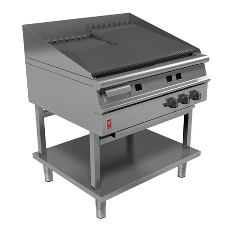
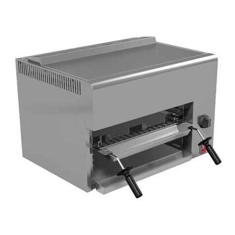
3.2 REMOVAL OF PANELS
a) Rem ve the enamelled fr nt facia by und ing the
fixings which secure it at the b tt m edge. Ease
the panel f rward at the b tt m and lift it clear f
the hidden l cati n screws.
b) Rem ve the t p panel by und ing ut the fixings at
the rear and slide the panel backward clear f the
fr nt l cati n.
c) Rem ve the inner t p panel t exp se the burners.
d) Rem ve the side and rear panels by und ing the
appr priate fixings.
3.3 REMOVAL of PLAQUES and BURNERS
3.3.1 Plaques Only
a) Rem ve the drip tray, grid shelf and brander and
als the uter panels as detailed in Secti n 3.2.
b) Plaques may be replaced by reaching inside the
t p f the grill c mpartment and placing y ur
fingers n the plaque face. Push the plaque up
carefully t disl dge it fr m the seating between
the bars and the supp rt angle.
c) Carefully replace the plaque s that it is pr perly
seated n the bar and supp rt angle. The plaque
sh uld be p siti ned hard against the burner.
3.3.2 Burner
a) Rem ve the fixings at the rear and b tt m f the
RH uter side panel and lift clear.
b) Rem ve the supp rt bars and plaques. Place
these in a safe l cati n until servicing is c mplete.
c) Und the nut which secures the pil t pipe t the
c ntr l tap and rem ve the pipe.
d) Und the nut which secures the therm c uple t
the c ntr l and rem ve the therm c uple.
e) Rem ve the igniter lead fr m the Piez igniter. Lift
the burner ab ve the inject r and withdraw.
f) The pil t may n w be rem ved fr m the burner by
und ing the fixings which secure it.
3.4 REMOVAL OF INJECTOR
F ll wing rem val f the burner, the inject r may be
cleaned r replaced as desired. See Secti n 1.8 f r
inject r dimensi n details.
3.5 BURNER and INJECTOR CLEANING
Burners require t be cleaned peri dically t ensure
that the p rts are free fr m bl ckage. This may be
facilitated by means f wire brushing. Individual p rts
may be cleared with a suitable metal instrument.
Disl dged material sh uld then be shaken ut f the
pen burner end.
Sh uld it bec me necessary t wash the burner(s),
ensure that they are c mpletely dry and free fr m
cleaning materials bef re re-fitting t the appliance.
The inject rs als require regular inspecti n and may
be cleaned with a w den splinter r fuse wire. Hard
metal impliments MAY DAMAGE THE ORIFICE and
MUST NOT be used.
Up n re-fitting, check adjustment and flame picture
as described in Secti n 2.5.2 f this d cument.
3.6 FLAME FAILURE THERMOCOUPLE
a) Rem ve the RH uter side panel.
b) Und the nut which secures the therm c uple t
the SIT pil t bracket using a 10mm spanner.
c) Und the nut which secures the therm c uple t
the gas tap.
d) Withdraw the faulty therm c uple and replace.
3.7 GAS VALVE
3.7.1 To Remo e
Pr ceed as f ll ws -
a) Pull ff the c ntr l kn bs and rem ve the fr nt
facia panel.
b) Und the nut whic secures the burner feed pipe t
the c ntr l.
c) Release the pil t tubing nut fr m the c ntr l and
ease the pil t tube clear f it's l cati n.
d) Rem ve the fixings which secure the c ntr l t the
gas pipe.
e) Man euvre the c ntr l t enable rem val f the
therm c uple.
f ) Withdraw the c ntr l.
3.7.2 To Re-grease The Control Tap
a) Rem ve the fixings which retain the fr nt securing
plate whilst h lding the plate against the internal
spring pressure.
b) Carefully withdraw the plate, c mplete with
perating spindle.
c) Withdraw the exp sed r d, spring, brass washer,
and sealing washer, taking care n t t l se any
parts.
d) Withdraw the plug and clean with a s ft rag and
als clean the mating surfaces in the c ntr l b dy.
Sparingly re-grease the plug with an appr ved
heat resistant grease.
Re-assemble in reverse rder taking care with the
central pin assembly. Fit the spring t the pin first,
then the brass washer and finally the sealing washer.
Ensure that the sealing washer fits snugly int the
recess at the base f the plug. When re-fitting the
perating spindle, ensure that the niting pin engages
in the plug sl t.
