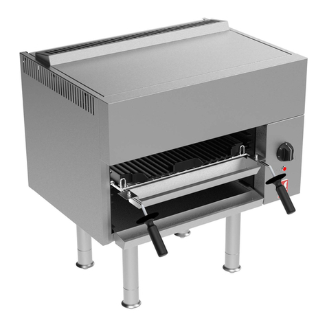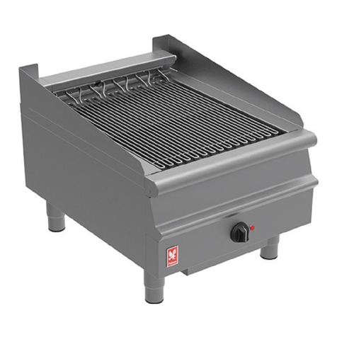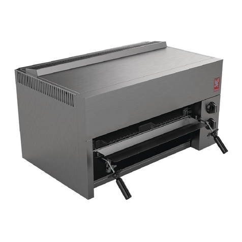
Nat ral
Propane
mbar
15.5
37
inches w.g
6.2
14.8
mbar
20
14.8
inches w.g
8
14.8
B rner Press re S pply Press re
1.9 GAS PRESSURE
The press re test point is sit ated on gas manifold
behind front facia panel.
1.10 BURNER ADJUSTMENTS
1.10.1 Aeration Adjustment
The b rners are fitted with fixed injectors.
Aeration is set and sealed by man fact rer by means
of a screw in b rner throat. After setting the press re,
flame q ality sho ld be s ch that there is no evidence
of flame lift or light back. Also refer to Servicing
Instr ctions, Section 3.3.
1.10.2 Low Flame Setting
Low flame adj stment has been set and sealed by
man fact rer by means of a bypass screw in gas tap
to approximately half f ll rate.
SECTION 2 - ASSEMBLY and
COMMISSIONING
2.1 ASSEMBLY
1. The b rners, bottomgrates and cooking bars are
removed from their working locations and
separately packed, together with a bag of
lava-rock. Remove these components and
caref lly remove all packing material.
2. Locate b rners (one only on G350/9) over injectors
at front, and engage rear locating toes thro gh
corresponding holes in rear s pporting angle.
3. Place hearth-s rro nd into casing with tilting
handles to front and ens re that fat tro gh is
correctly located.
4. Lay bottomgrates in position (Two on G350/9 and
Fo r on G350/10), ens ring the locating toes on
nderside engage in corresponding holes in hearth
s rro nd.
5. LAVA ROCK - DO NOT tip contents of bag of rock
into grates. The d st, which acc m lates nat rally
at the bag bottom d ring shipment, m st be
discarded as it will clog b rner ports and affect
nit performance. Set a single layer of lava rock,
spread evenly over grate area (see User
Instr ctions). Discard any small chips of rock as
these may lodge between grates and block heat
flow.
6. Fit brander bars (Three on G350/9 and Six on
G350/10) with flanges toward rear.
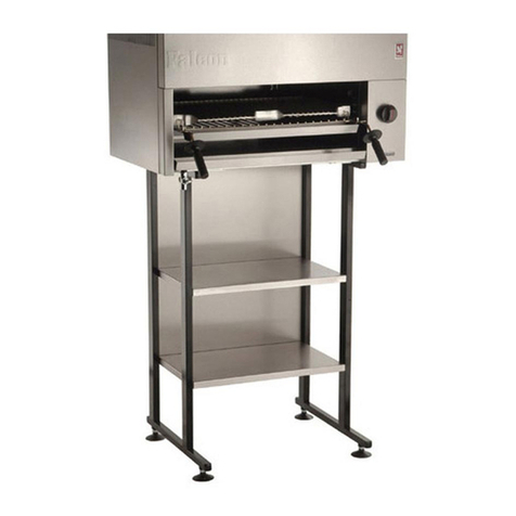
7. Having assembled appliance, place it in it's working
position and level it sing the feet adj sters. If it is
to be mo nted on the special p rpose metal stand.
Refer to instr ctions s pplied with stand.
2.2 CONNECTION TO GAS SUPPLY
The gas s pply piping and connection to nit m st be
installed in accordance with the vario s reg lations
listed on the cover of this man al.
On Nat ral Gas appliances, the adj stable governor
s pplied MUST be fitted in the s pply, being sec rely
fixed in a position enabling adj stments to be made
d ring commissioning. On Propane nits, a governor
m st NOT be fitted.
2.3 CONNECTING TO AN ELECTRICAL SUPPLY
Not applicable to these appliances.
2.4 CONNECTION TO WATER SUPPLY
Not applicable to these appliances.
2.5 PRE-COMMISSIONING CHECK
After connecting to gas s pply, fit a press re ga ge to
the test point (see Installation, Section 1.9) and check
entire installation for gas tightness. P rge air from
system and light b rners in accordance with
proced res detailed below. On Nat ral Gas models,
set press re by means of the governor.
Lighting The Burners
DO NOT attempt to light b rners thro gh the
sim lated charcoal with a match or short taper
beca se of the risk of b rns.
To Turn A Burner ON (see Figure 1).
A taper (at least 230mm in length) is req ired.
The following proced re applies to two-b rner model
(G350/10).
For single b rner nit (G350/9), the lighting operation
will of co rse be performed once only.
P ll o t fat drawer and apply a lit taper thro gh centre
of opening and light either left or right pilot depending
on which b rner req ires to be lit. T rn gas tap to
req ired flame position for selected b rner.
Check thro gh viewing window that b rner is f lly
alight before replacing fat drawer.
Repeat above to light other b rner.
OFF Position IGNITION Position
FULL ON Position LOW FLAME Position


