manuals.online logo
Brands
  1. Home
  2. •
  3. Brands
  4. •
  5. Falcon
  6. •
  7. Grill
  8. •
  9. Falcon G350/9 User guide

Falcon G350/9 User guide

T100693 Ref. 2
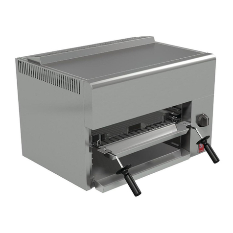
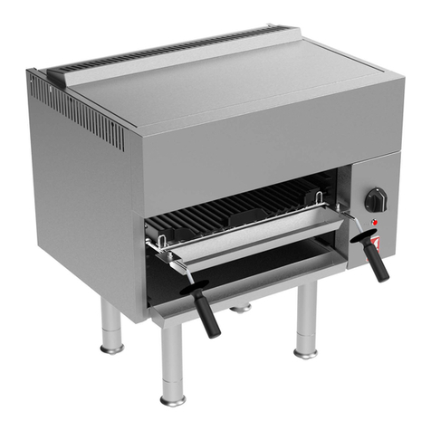
G350/9 and G350/10
CHARGRILLS
INSTALLATION and
SERVICING INSTRUCTIONS
These appliances must be installed and serviced b a competent person as stipulated b the Gas
Safet (Installation & Use) Regulations.
IMPORTANT
The installer ust ensure that the installation of the appliance is in confor ity with these instructions and
National Regulations in force at the ti e of installation. Particular attention MUST be paid to -
Gas Safet ( Installation & Use ) Regulations
Health And Safet At Work etc. Act
Local and National Building Regulations
Fire Precautions Act
These Appliances have been CE- arked on the basis of co pliance with the Gas Appliance Directive for the
Countries, Gas Types and Pressures as stated on the data plate.
WARNING
TO PREVENT SHOCKS, ALL APPLIANCES WHETHER GAS OR ELECTRIC, MUST BE EARTHED.
On co pletion of the installation, these instructions should be left with the Engineer-in-Charge for reference
during servicing. Further to this, The Users Instructions should be handed over to the User, having had a
de onstration of the operation and cleaning of the Appliance.
IT IS MOST IMPORTANT THAT THESE INSTRUCTIONS BE CONSULTED BEFORE INSTALLING AND
COMMISSIONING THIS APPLIANCE. FAILURE TO COMPLY WITH THE SPECIFIED PROCEDURES MAY
RESULT IN DAMAGE OR THE NEED FOR A SERVICE CALL.
PREVENTATIVE MAINTENANCE CONTRACT
In order to obtain axi u perfor ance fro this unit we would reco end that a Maintenance Contract be
arranged with SERVICELINE. Visits ay then be ade at agreed intervals to carry out adjust ents and
repairs. A quotation will be given upon request to the contact nu bers below.
WEEE Directive Registration No. WEE/DC0059TT/PRO
At end of unit life, dispose of appliance and any replace ent parts
in a safe anner, via a licenced waste handler.
Units are designed to be dis antled easily and recycling of all
aterial is encouraged whenever practicable.
Falcon Foodservice Equipment
HEAD OFFICE AND WORKS
Wallace View, Hillfoots Road, Stirling. FK9 5PY. Scotland.
SERVICELINE CONTACT -
PHONE - 01438 363 000 FAX - 01438 369 900
Detailed recommendations are contained in
Institute of Gas Engineers published
documents :
IGE/ UP/ 1, IGE/ UP/ 2
BS6173 and BS5440
Warrant Polic Shortlist
Warranty does not cover :-
Correcting faults caused by incorrect installation of a product.
Where an engineer cannot gain access to a site or a product.
Repeat co ission visits.
Replace ent of any parts where da age has been caused by isuse.
Engineer waiting ti e will be chargeable.
Routine aintenance and cleaning.
Gas conversions i.e. Natural to Propane gas.
Descaling of water products and cleaning of water sensors where softeners/conditioners are not fitted, or are
fitted and not aintained.
Blocked drains.
Independent stea generation syste s.
Gas, water and electrical supply external to unit.
Light bulbs.
Re-installing vacuu in kettle jackets.
Replace ent of grill burner cera ics when da age has been clearly caused by isuse.
Where an engineer finds no fault with a product that has been reported faulty.
Re-setting or adjust ent of ther ostats when unit is operating to specification.
Cleaning and unblocking of fryer filter syste s due to custo er isuse.
Lubrication and adjust ent of door catches.
Cleaning and Maintenance
Cleaning of burner jets
Poor co bustion caused by lack of cleaning
Lubrication of oving parts
Lubrication of gas cocks
Cleaning/adjust ent of pilots
Correction of gas pressure to appliance.
Renewing of electric cable ends.
Replace ent of fuses
Corrosion caused by use of che ical cleaners.
MODEL kW (net) Btu/hr (gross)
G350/9 9.6 36,000
G350/10 19.2 72,000
BURNER NATURAL PROPANE
MAIN ù2.9 A al 390
PILOT N16 LP 10
SECTION 1 - INSTALLATION
1.2 SITING
The appliance should be installed on a level, fireproof
surface in a well lit and draught free position.
Should the floor be of co bustible aterial, then local
fire require ents should be checked to ensure
co pliance. A clearance of 150 should be left
between the back and sides of the appliance and any
co bustible wall. There should be a ini u vertical
clearance of 1650 above top edge of chargrill flue.
The chargrill rear beco es VERY HOT. If installed in
a free-standing position, appliance rear MUST BE
GUARDED to protect operators against burns.
Important
If the appliance is to be installed in a suite for ation
with atching appliances then the instructional
literature for these should be consulted in order to
deter ine the necessary clearances to any
co bustible rear wall or overlying surface(s). So e
units require greater clearances than others.
The largest figure quoted in the individual instructions
will therefore deter ine the clearance of the co plete
suite adjoining appliances.
1.3 VENTILATION
Adequate ventilation, whether natural or echanical,
ust be provided to supply sufficient fresh air for
co bustion and allow easy re oval of co bustion
products which ay be har ful to health.
Reco endations for Ventilation of Catering
Appliances are given in BS5440 : 2. Further ore,
to ensure sufficient roo ventilation, guidance on the
volu e of ventilation air required for different types of
catering equip ent is provided in the table.
For ultiple installations the require ents for
individual appliances should be added together.
Installation should be ade in accordance with local
and/or national regulations applying at the ti e.
A co petent installer MUST be e ployed.
1.4 GAS SUPPLY
The inco ing service ust be of sufficient size to
supply full heat without excessive pressure drop.
A gas eter will be installed in the syste by Gas
Supplier. Any existing eter should be checked,
preferably by Gas Supplier to ensure that it is of
adequate capacity to supply the entire installation.
This is, of course, particularly i portant when a
nu ber of units, (i.e. a "suite" is being installed.)
Installation pipework ust be fitted in accordance
with IGE/ UP/ 2.
The size of pipework supplying the appliance ust be
not less than the inlet connection (R
1
/
2
,
1
/
2
" BSP).
An isolating cock ust be located close to the
appliance to allow shut down during an e ergency
or routine servicing.
After installation, the co plete installation ust be
checked for gas tightness: see IGE/ UP/ 1.
1.5 ELECTRICAL SUPPLY
Not applicable to these appliances.
1.6 WATER SUPPLY
Not applicable to these appliances.
1.7 TOTAL RATED HEAT INPUTS -
NATURAL and PROPANE GAS
1.8 INJECTOR SIZE -
NATURAL and PROPANE GAS
EQUIPMENT
Ventilation Rate Required
3
/ in ft
3
/ in
Range, Unit Type 17 600
Pastry Oven 17 600
Fryer 26 900
Grill 17 600
Steak Grill 26 900
Boiling Pan 17 600
Stea er 17 600
Sterilizing Sink 14 500
Bains Marie 11 400
Tea/ Coffee Machine 8.5 - 14 300 - 500
UNLESS OTHERWISE STATED, PARTS WHICH HAVE BEEN PROTECTED BY THE MANUFACTURER
ARE NOT TO BE ADJUSTED BY THE INSTALLER
MODEL WIDTH
DEPTH
HEIGHT
WEIGHT
kg WEIGHT
lbs
G350/9 350 650 305 46 101
G350/10 700 650 305 78 172
1.1 MODEL NUMBERS, NETT WEIGHTS
and DIMENSIONS
Natural
Propane
bar
15.5
37
inches w.g
6.2
14.8
bar
20
14.8
inches w.g
8
14.8
Burner Pressure Supply Pressure
1.9 GAS PRESSURE
The pressure test point is situated on gas anifold
behind front facia panel.
1.10 BURNER ADJUSTMENTS
1.10.1 Aeration Adjustment
The burners are fitted with fixed injectors.
Aeration is set and sealed by anufacturer by eans
of a screw in burner throat. After setting the pressure,
fla e quality should be such that there is no evidence
of fla e lift or light back. Also refer to Servicing
Instructions, Section 3.3.
1.10.2 Low Flame Setting
Low fla e adjust ent has been set and sealed by
anufacturer by eans of a bypass screw in gas tap
to approxi ately half full rate.
SECTION 2 - ASSEMBLY and
COMMISSIONING
2.1 ASSEMBLY
1. The burners, botto grates and cooking bars are
re oved fro their working locations and
separately packed, together with a bag of
lava-rock. Re ove these co ponents and
carefully re ove all packing aterial.
2. Locate burners (one only on G350/9) over injectors
at front, and engage rear locating toes through
corresponding holes in rear supporting angle.
3. Place hearth-surround into casing with tilting
handles to front and ensure that fat trough is
correctly located.
4. Lay botto grates in position (Two on G350/9 and
Four on G350/10), ensuring the locating toes on
underside engage in corresponding holes in hearth
surround.
5. LAVA ROCK - DO NOT tip contents of bag of rock
into grates. The dust, which accu ulates naturally
at the bag botto during ship ent, ust be
discarded as it will clog burner ports and affect
unit perfor ance. Set a single layer of lava rock,
spread evenly over grate area (see User
Instructions). Discard any s all chips of rock as
these ay lodge between grates and block heat
flow.
6. Fit brander bars (Three on G350/9 and Six on
G350/10) with flanges toward rear.
7. Having asse bled appliance, place it in it's working
position and level it using the feet adjusters. If it is
to be ounted on the special purpose etal stand.
Refer to instructions supplied with stand.
2.2 CONNECTION TO GAS SUPPLY
The gas supply piping and connection to unit ust be
installed in accordance with the various regulations
listed on the cover of this anual.
On Natural Gas appliances, the adjustable governor
supplied MUST be fitted in the supply, being securely
fixed in a position enabling adjust ents to be ade
during co issioning. On Propane units, a governor
ust NOT be fitted.
2.3 CONNECTING TO AN ELECTRICAL SUPPLY
Not applicable to these appliances.
2.4 CONNECTION TO WATER SUPPLY
Not applicable to these appliances.
2.5 PRE-COMMISSIONING CHECK
After connecting to gas supply, fit a pressure gauge to
the test point (see Installation, Section 1.9) and check
entire installation for gas tightness. Purge air fro
syste and light burners in accordance with
procedures detailed below. On Natural Gas odels,
set pressure by eans of the governor.
Lighting The Burners
DO NOT atte pt to light burners through the
si ulated charcoal with a atch or short taper
because of the risk of burns.
To Turn A Burner ON (see Figure 1).
A taper (at least 230 in length) is required.
The following procedure applies to two-burner odel
(G350/10).
For single burner unit (G350/9), the lighting operation
will of course be perfor ed once only.
Pull out fat drawer and apply a lit taper through centre
of opening and light either left or right pilot depending
on which burner requires to be lit. Turn gas tap to
required fla e position for selected burner.
Check through viewing window that burner is fully
alight before replacing fat drawer.
Repeat above to light other burner.
OFF Position IGNITION Position
FULL ON Position LOW FLAME Position
Burner Adjustment Checks
With burner lit, check fla e quality and low fla e
setting are in accordance with Section 1.10.
To Turn A Burner OFF
Turn gas tap clockwise to stop, as shown in Figure 1.
Important
After installation, the engineer responsible should
check that all gas connections are good and tight.
Ensure unit is operating satisfactorily before leaving
the pre ises.
2.6 INSTRUCTION TO USER
After installing and co issioning appliance, please
hand User Instructions to user or purchaser and
ensure that the person(s) responsible understands
instructions for lighting, cleaning and correct use of
unit. It is i portant to ensure that location of gas
isolating cock is ade known to user and that the
procedure for operation in an e ergency be
de onstrated.
SECTION 3 - SERVICING and
CONVERSION
Important
BEFORE ATTEMPTING ANY SERVICING,
ENSURE THAT ISOLATING COCK IS TURNED
OFF AND CANNOT BE INADVERTANTLY TURNED
ON.
AFTER ANY MAINTENANCE TASK, CHECK
APPLIANCE TO ENSURE THAT IT PERFORMS
CORRECTLY AND CARRY OUT ANY NECESSARY
ADJUSTMENTS AS DETAILED IN SECTION 1.
After carrying out any servicing or exchange of gas
carrying co ponents -
ALWAYS CHECK FOR GAS TIGHTNESS!!
3.1 CONVERSION TO OTHER GASES
This unit ay be set for operation with Natural Gas
(2H) at supply pressure of 20 bar or propane (3P) at
37 bar.
For detailed procedures, refer to appropriate sections
of this docu ent.
On co pletion, reapply any seals and locking nuts.
To Convert From NATURAL to PROPANE Gas
Change gas valve(s).
Change injectors.
Re ove governor.
Adjust low fla e setting.
Adjust burner aeration.
Change data plate.
To Convert From PROPANE to NATURAL Gas
Change gas valve(s).
Change injectors.
Install governor and adjust for inlet pressure
accordingly.
Adjust low fla e setting.
Adjust burner aeration.
Change data plate.
3.2 REMOVAL OF CONTROL PANEL
To re ove control panel, pull off control knobs and
re ove fat-collecting drawer.
Re ove fixings in top flange of facia panel,
then lower panel and withdraw it forward.
3.3 BURNERS
Burners and injectors should be cleaned periodically
to aintain axi u perfor ance.
3.3.1 Main Burner
The adjust ent of burner pressure is described in
Section 1.9. Burners are accessed by re oving lava
rock, botto grates and hearth surround.
Burners are best cleaned with a wire brush,
ports being freed fro blockage with a etal broach,
any loose aterial being shaken out via burner
shank. Ensure that burners are dry and free fro
any cleaning aterial before replacing.
3.3.2 Pilot Assembl
To re ove proceed as follows:
a) Re ove branding bars, lava rock, botto grates
and hearth.
b) Release the ocouple fixing nut and re ove
ther ocouple fro asse bly.
c) Release pilot pipe fixing nut fro pilot asse bly
taking care not to lose injector re oved with nut.
d) Undo fixing which secures pilot asse bly.
e) Re-asse ble in reverse order.
3.4 INJECTORS
Should ain injectors beco e blocked, re ove these
fro chargrill for cleaning. First re ove lava rock,
botto grates, hearth and burners. Unscrew injectors
using a suitable spanner. Soak in solvent to re ove
blockage.
3.5 FLAME FAILURE THERMOCOUPLE
To gain access, re ove front panel and hearth
surround.
To re ove ther ocouple fro pilot asse bly, undo
fixing nut fro within control co part ent and
withdraw.
To re ove ther ocouple fro gas tap, undo fixing
nut on tap body.
3.6 GAS TAPS
To Service
Re ove the fixings fro front of tap body and
withdraw spindle and niting arrange ent thus
allowing plug to be eased out.
Clean plug and body with a soft rag and re-grease
with an approved high te perature lubricant. Apply
grease sparingly and do not block gas passageways
of plug and body.
When re-asse bling parts, insert plug into body with
gas passageways of plug and body.
Secure end cap to body, noting that fixing holes line
up in one way only.
Note
Plugs and bodies are achined in pairs and are
therefore not interchangeable. Always clean one tap
at a ti e.
To Remove
Undo brass nut at co pression fitting on gas supply
pipe at rear of gas tap.
Re ove ther ocouple connection fro FFD section
of tap.
Undo fixings and gently re ove tap fro supply
anifold.
3.7 GOVERNOR
This applies to NATURAL GAS appliances only.
The type of governor used is aintenance free.
Check blue dust cap covering vent is fitted and in
good condition. This protects breather hole.
SECTION 4 - SPARES
When ordering spare parts, always quote the
appliance type and serial nu ber. This infor ation
will be found on the data plate, located on a plate
behind the rear flue upstand. A list of ite s available,
along with code nu bers is enclosed with the
docu ent pack.

This manual suits for next models

1

Other Falcon Grill manuals

Falcon G2522 User guide

Falcon

Falcon G2522 User guide

Falcon G2522 User manual

Falcon

Falcon G2522 User manual

Falcon G2625 User manual

Falcon

Falcon G2625 User manual

Falcon G3625 User manual

Falcon

Falcon G3625 User manual

Falcon DOMINATOR PLUS E3625 User manual

Falcon

Falcon DOMINATOR PLUS E3625 User manual

Falcon STEAKHOUSE PLUS G1528 User manual

Falcon

Falcon STEAKHOUSE PLUS G1528 User manual

Falcon STEAKHOUSE PLUS G1528 User guide

Falcon

Falcon STEAKHOUSE PLUS G1528 User guide

Falcon Dominator Plus G3512 User guide

Falcon

Falcon Dominator Plus G3512 User guide

Falcon E2522 User guide

Falcon

Falcon E2522 User guide

Falcon G3425 User guide

Falcon

Falcon G3425 User guide

Falcon G350/10 Manual

Falcon

Falcon G350/10 Manual

Falcon STEAKHOUSE PLUS G1528 User manual

Falcon

Falcon STEAKHOUSE PLUS G1528 User manual

Falcon G3425 User manual

Falcon

Falcon G3425 User manual

Falcon G9440 Manual

Falcon

Falcon G9440 Manual

Falcon Elan U109645 - 02 Installation and maintenance instructions

Falcon

Falcon Elan U109645 - 02 Installation and maintenance instructions

Falcon E600 Manual

Falcon

Falcon E600 Manual

Falcon G2625 User manual

Falcon

Falcon G2625 User manual

Falcon SREAKHOUSE PLUS G1518 User guide

Falcon

Falcon SREAKHOUSE PLUS G1518 User guide

Falcon G3425 User guide

Falcon

Falcon G3425 User guide

Falcon G350/9 User manual

Falcon

Falcon G350/9 User manual

Falcon STEAKHOUSE PLUS G1528 User manual

Falcon

Falcon STEAKHOUSE PLUS G1528 User manual

Falcon G2522 User manual

Falcon

Falcon G2522 User manual

Falcon Dominator Plus E3625 User guide

Falcon

Falcon Dominator Plus E3625 User guide

Falcon G9622 User manual

Falcon

Falcon G9622 User manual

Popular Grill manuals by other brands

KitchenAid 730-0891C (NG) Installation Instructions and Use & Care Guide

KitchenAid

KitchenAid 730-0891C (NG) Installation Instructions and Use & Care Guide

Weber ELECTRIC GRILL owner's guide

Weber

Weber ELECTRIC GRILL owner's guide

Waring HDG100 manual

Waring

Waring HDG100 manual

Napoleon APOLLO user manual

Napoleon

Napoleon APOLLO user manual

Dyna-Glo DGP700SSB-D User's manual and operating instructions

Dyna-Glo

Dyna-Glo DGP700SSB-D User's manual and operating instructions

Gasmate Gemini GM172-120 manual

Gasmate

Gasmate Gemini GM172-120 manual

Iron Chief America 87695 owner's manual

Iron Chief America

Iron Chief America 87695 owner's manual

Cadco CPG-10 Use and care guidelines

Cadco

Cadco CPG-10 Use and care guidelines

IKEA GRILLSKÄR quick start guide

IKEA

IKEA GRILLSKÄR quick start guide

APURO D474-A instruction manual

APURO

APURO D474-A instruction manual

Jenn-Air JGD8130 series installation manual

Jenn-Air

Jenn-Air JGD8130 series installation manual

PERMASTEEL PG-40400S0L user manual

PERMASTEEL

PERMASTEEL PG-40400S0L user manual

Vivax EG-5025 user manual

Vivax

Vivax EG-5025 user manual

Fiesta EHA2240-B404 user manual

Fiesta

Fiesta EHA2240-B404 user manual

Kogan Cookmaster CKPTPRGRLA user guide

Kogan

Kogan Cookmaster CKPTPRGRLA user guide

Hamilton Beach 86201 manual

Hamilton Beach

Hamilton Beach 86201 manual

Mustang 263591 quick start guide

Mustang

Mustang 263591 quick start guide

Viking Outdoor Use & care manual

Viking

Viking Outdoor Use & care manual

manuals.online logo
manuals.online logoBrands
  • About & Mission
  • Contact us
  • Privacy Policy
  • Terms and Conditions

Copyright 2025 Manuals.Online. All Rights Reserved.