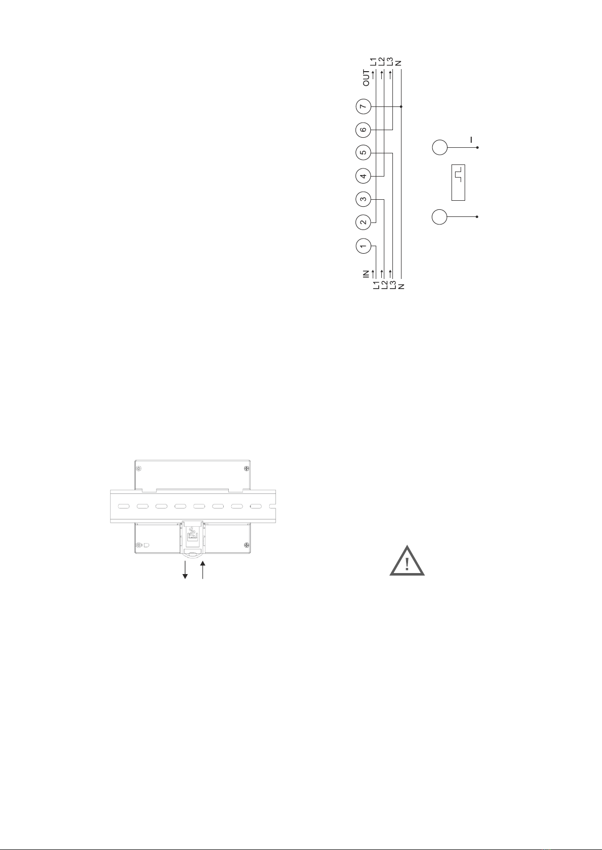
manuals.online logo
Brands
  1. Home
  2. •
  3. Brands
  4. •
  5. F&F
  6. •
  7. Measuring Instrument
  8. •
  9. F&F LE-03 User manual

F&F LE-03 User manual

F&F Filipowski sp. j.
Konstantynowska 79/81 95-200 Pabianice
phone/fax: (+48 42) 215 23 83 / 227 09 71 POLAND
http://www.fif.com.pl e-mail: fif@fif.com.pl
ELECTRICITY CONSUMPTION METER
three-phase
Do not dispose of this device to a garbage bin with other unsorted waste!
In accordance with the Waste Electrical and Electronic Equipment Act
any household electro-waste can be turned in free of charge and in any
quantity to a collection point established for this purpose, as well as to the
store in the event of purchasing new equipment (as per the old for new rule,
regardless of brand). Electro-waste thrown in the garbage bin or abandoned
in the bosom of nature pose a threat to the environment and human health.
LE-03
WARRANTY. The F&F products are
covered by a warranty of the 24 months
from the date of purchase. Effective only
with proof of purchase. Contact your
dealeror directly with us. More infor-
mation how to make a compliant can be
found on the website:
www.fif.com.pl/reklamacje
Sealing
Meter number
Dimensions
Pulse output
The meter is equipped with pulse output SO+ - SO-. This allows
you to connect another pulse device (SO) that reads pulses
generated by the meter.
No additional connected equipment is required for proper opera-
tion of the meter.
The meter has sealable input and output terminal covers
to prevent any attempts to bypass the meter.
The meter is marked with individual serial number allowing its
unambiguous identification. The marking is laser engraved and
cannot be removed.
Length of the SO+ SO- pulses depends on the load of the meter:
5÷40A 80 ms 75A 46 ms
45A 75 ms 80A 42 ms
50A 68 ms 85A 40 ms
55A 62 ms 90A 38 ms
60A 57 ms 95A 36 ms
65A 52 ms 100A 34 ms
70A 48 ms
Purpose
Functioning
LE-03 is a static (electronic) calibrated electricity meter of three-
phase alternating current in a direct system.
A special electronic system under the influence of flowing current
and applied voltage in each phase generates pulses proportional
to the energy drawn in the respective phase. Energy consumption
in the phase is indicated by a flashing of corresponding LED (A, B,
C). The sum of the three phase pulses is indicated by a flashing LED
(800 pulses/kWh) and converted into energy absorbed
throughout the three-phase system. Its value is displayed by the
segment LCD display. The fractional digit represent the decimal
(.1 kWh = 100Wh).
Meter front description
LCD display
kWh reading LED
meter number
terminal covers
sealing points
A B C imp/kWh
phase load LED
888888.8
- 1- - 2-
- 3- - 4-
5 9 0 8 3 1 2 5 9 1 7 0 2
Installation
Connection diagram
SO
+
98
D141020
* Please read the manual carefully prior to installing the meter.
* The meter should be installed and operated by qualified per-
sonnel familiar with the construction, operation and any
hazards involved.
* Do not install the meter if it is damaged or incomplete.
* The user is responsible for proper grounding, selection, instal-
lation and functionality of any other devices connected to the
meter, including security devices such as overcurrent protec-
tion breakers, differential switches and surge protectors.
* Before connecting the power supply make sure that all cables
are connected properly.
* Always follow the operational conditions of the meter (voltage,
humidity, temperature).
* In order to avoid electric shock or damage to the meter, discon-
nect the power before each change in connection configu-
ration.
* Do not modify the device on your own, as this may cause dama-
ge or improper operation of the meter and consequently
expose the users to risk. In these cases the manufacturer is not
liable for ensuing events and reserves the right to refuse the
warranty claims on the counter.
General safety conditions
Technical data
reference voltage 3×230/400V+N
base current 10A
maximum current 100A
minimum current 0.04A
st
accuracy class 1 class
compliance IEC61036
own power consumption <10VA; <2W
indication range 0÷999999.9kWh
meter constant (1.25 Wh/pulse) 800pulses/kWh
current consumption signalling L1, L2, L3 phases 3× red LED
kWh read-out signalling red LED
SO+ SO- pulse output open collector
SO+ SO- connection voltage <12÷27V DC
SO+ SO- connection current <27mA
SO+ SO- constant (1.25 Wh/pulse) 800pulses/kWh
SO+ SO- pulse duration (load-dependent) 34÷80msec
SO+ SO- wire length <20m
working temperature -20÷55°C
terminal 25mm² screw terminals
housing ABS material
dimensions 7 modules (122×100×65mm)
mounting on TH-35 rail
ingress protection IP20
1. Disconnect the switching station power.
2. Mount the meter on the TH rail in the distribution box.
3. Open the covers on the terminals.
4. Connect the power to terminal 1 (L1 IN), terminal 3 (L2 IN),
terminal 5 (L3 IN).
5. Connect a measured circuit or a single receiver to terminal 2
(L1 OUT), terminal 4 (L2 OUT), terminal 6 (L3 OUT).
6. Connect wire N to terminal 7.
7. Optionally connect the RS-485 network wires to the 9(A+) -
8(B-) terminals.
8. Close the covers on the terminals and optionally seal them.
1 2
- 5- - 6-
- 7- - 8-

Other F&F Measuring Instrument manuals

F&F LE-03MQ User manual

F&F

F&F LE-03MQ User manual

F&F WZE-1 User manual

F&F

F&F WZE-1 User manual

F&F CLI-01 User manual

F&F

F&F CLI-01 User manual

F&F LE-03MP User manual

F&F

F&F LE-03MP User manual

F&F LE-03d User manual

F&F

F&F LE-03d User manual

F&F CLG-03 User manual

F&F

F&F CLG-03 User manual

F&F LE-01MR v2 User manual

F&F

F&F LE-01MR v2 User manual

F&F LE-02d CT User manual

F&F

F&F LE-02d CT User manual

F&F WNC-3 User manual

F&F

F&F WNC-3 User manual

F&F LE-03M CT User manual

F&F

F&F LE-03M CT User manual

F&F LE-01MR User manual

F&F

F&F LE-01MR User manual

F&F WN-711 User manual

F&F

F&F WN-711 User manual

F&F WN-711S User manual

F&F

F&F WN-711S User manual

F&F LE-03MW User manual

F&F

F&F LE-03MW User manual

F&F LE-01MW User manual

F&F

F&F LE-01MW User manual

F&F LE-02d User manual

F&F

F&F LE-02d User manual

F&F CLG-03 User manual

F&F

F&F CLG-03 User manual

F&F LE-01MR v2 User manual

F&F

F&F LE-01MR v2 User manual

F&F LE-03d CT400 User manual

F&F

F&F LE-03d CT400 User manual

F&F LE-03 User manual

F&F

F&F LE-03 User manual

F&F DMA-1 CT TrueRMS User manual

F&F

F&F DMA-1 CT TrueRMS User manual

F&F LE-03MQ User manual

F&F

F&F LE-03MQ User manual

F&F DMA-3 CT TrueRMS User manual

F&F

F&F DMA-3 CT TrueRMS User manual

F&F LE-03MB User manual

F&F

F&F LE-03MB User manual

Popular Measuring Instrument manuals by other brands

Ambient Weather WS-YG501 manual

Ambient Weather

Ambient Weather WS-YG501 manual

Sanwa DCL31DR instruction manual

Sanwa

Sanwa DCL31DR instruction manual

Bante Instruments 810 user manual

Bante Instruments

Bante Instruments 810 user manual

Emerson Rosemount 3814 Maintenance and troubleshooting manual

Emerson

Emerson Rosemount 3814 Maintenance and troubleshooting manual

Rice Lake DIGI DS-520 Operation manual

Rice Lake

Rice Lake DIGI DS-520 Operation manual

RUSTA 775100010101 manual

RUSTA

RUSTA 775100010101 manual

3M Workstation Monitor 724 user guide

3M

3M Workstation Monitor 724 user guide

Endress+Hauser Proline Promag D 400 Brief operating instructions

Endress+Hauser

Endress+Hauser Proline Promag D 400 Brief operating instructions

Maxtec MaxO2 ME+p Instructions for use

Maxtec

Maxtec MaxO2 ME+p Instructions for use

RMG WMTWLI installation manual

RMG

RMG WMTWLI installation manual

Klein Tools CL390 instruction manual

Klein Tools

Klein Tools CL390 instruction manual

OfiTE 800 instruction manual

OfiTE

OfiTE 800 instruction manual

HyQuest Solutions HS40C user manual

HyQuest Solutions

HyQuest Solutions HS40C user manual

Great Scott Gadgets Throwing Star LAN Tap instructions

Great Scott Gadgets

Great Scott Gadgets Throwing Star LAN Tap instructions

PT PT200P Operator's manual

PT

PT PT200P Operator's manual

iSystem ARM HSSTP user manual

iSystem

iSystem ARM HSSTP user manual

Geosense WI-SOS 480 instruction manual

Geosense

Geosense WI-SOS 480 instruction manual

Emerson Rosemount 3410 Series installation manual

Emerson

Emerson Rosemount 3410 Series installation manual

manuals.online logo
manuals.online logoBrands
  • About & Mission
  • Contact us
  • Privacy Policy
  • Terms and Conditions

Copyright 2025 Manuals.Online. All Rights Reserved.