manuals.online logo
Brands
  1. Home
  2. •
  3. Brands
  4. •
  5. FarmTek
  6. •
  7. Lawn And Garden Equipment
  8. •
  9. FarmTek 113502 User manual

FarmTek 113502 User manual

1
Revision date: 01.27.20
©2020 FarmTek®
All Rights Reserved. Reproduction
is prohibited without permission.
113502
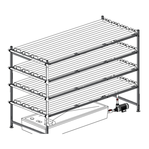
Ebb & Flow System
113502 4' x 8' System
System requires a timer to control the main pump and to set watering cycles. Additional purchase required.
ATTENTION: ACTUAL TRAY IS BLACK. ORIGINAL
WHITE TRAY IS NO LONGER AVAILABLE.
2Revision date: 01.27.20
REQUIRED TOOLS
The following list identifies the main tools needed to
assemble the system. Additional tools may be
needed.
• Level (4'– recommended)
• Wrench set to level frame
• Ratchet with 1/2" socket to assemble frame
• 3/16" hex (Allen) wrench—preferably one that
can be used in a socket to operate with a drill.
• Adjustable pliers and small hammer
• Gloves to handle tubing
• 1-1/8" and 1-3/8" hole saw bits
• Tool to cut 3/4" tubing
READ THIS DOCUMENT BEFORE YOU BEGIN
Thank you for purchasing the 113502 Ebb & Flo system. When properly assembled and maintained, this system will provide years of reliable service. These
instructions include helpful hints and important information needed to safely assemble the system. Please read and understand these instructions before you
begin. If you have any questions during the assembly, contact customer service.
ASSEMBLY PROCEDURE
Following the instructions as presented will help
ensure the proper assembly of your system.
The steps outlining the assembly process are as
follows:
1. Verify that all parts are included in the
shipment. Notify customer service for
questions or concerns. See below.
2. Read and understand these instructions and
the information included with the shipment
before you begin.
3. Gather the tools and assistants.
4. Assemble the system.
Important Information
SAFETY PRECAUTIONS
• Wear eye protection.
• Wear gloves when handling metal pipes.
• Use a portable GFCI (Ground Fault Circuit
Interrupter) when working with power tools and
cords.
112838
Tek Screw
FALB34B
112772
112770
113030S01
112477
FAME51B
FAG338B
PICTORIAL GUIDE
Larger parts may not be shown.
111303 111698
111301
111302
TIMER REQUIRED – ADDITIONAL PURCHASE
This system requires a timer to control water pump
and to set watering cycles. Timer is not included and
requires an additional purchase.
If you do not have a timer for your system, contact
your sales representative for additional information.
3
Revision date: 01.27.20
1ATTACH LEG TUBES
Assemble frame on a flat, level surface.
8-3/4"
8-3/4"
Assemble as shown. Legs are 8-3/4" from
the end of each FT15G16L09000S1 tube.
FT15VMGL01800S1
FT15G16L09000S1
FT15VMGL01800S1
112772 Flat
Head Bolt
8-3/4"
Attach Leg Tubes
112772
5/16" x 3" Flat
Head Bolt
112477
FALB34B
Complete these steps to install each 112477 insert:
1. Add one FALB34B nut to threaded stud of each
113030S01 foot and attach one foot to each
112477 insert.
2. Slide one 112477 insert assembly into bottom of
each 18" vertical leg tube. Tap gently with a small
hammer if needed to seat in place.
3. Secure each insert to each tube using two (2)
112838 Tek screws. Install screws through leg
tube and wall of the 112477 insert and not the
open side of the insert. Install screws slightly
off center line of the leg tube to prevent contact
with threaded rod.
4. Adjust 113030S01 leveler so it is seated against
threaded plate of insert and locknut. See diagram
to the right.
5. Secure leg tubes to the FT15G16L09000S1 tubes using the 112772 flat head bolts.
Bottom
of Leg
Tube
112477
FALB34B
Locknut
113030S01
x
x
Steps 3 & 4
4
4Revision date: 01.27.20
2
Assemble Main Frame
ASSEMBLE MAIN FRAME
Assemble frame on a flat, level surface.
1. Use the FAG338B (5/16" x 3") hex head bolts and FAME51B flat washers to complete
the frame assembly. Tighten all connections until snug.
2. Install one 112770 finishing cap in each horizontal frame tube. Gently tap into tube if
needed.
3. Level the frame as needed. Tighten locknut against the insert plate to secure leveler.
STEP 3
112770
STEP 2
FD15CMGL04900S1
FD15CMGL04900S1
STEP 1
FAME51B
FAG338B
5
Revision date: 01.27.20
3
Prepare Propagation Tray
PREPARE 111107 PROPAGATION TRAY (4' x 8')
Complete these steps to drill the holes in the propagation tray.
1. With assistance, carefully flip the tray over on the assembled frame so
the bottom is facing up.
2. At one end of the tray, locate the flat area with dimples that identify
hole locations.
3. Using a 1-3/8" hole saw bit and a drill, carefully drill the bulkhead
holes through the bottom of the propagation tray.
4. Clean debris from the tray and around the holes.
5. Continue with the installation of the bulkhead fittings.
ATTENTION: ACTUAL TRAY IS BLACK. ORIGINAL
WHITE TRAY IS NO LONGER AVAILABLE.
6
6Revision date: 01.27.20
4
Install Bulkhead Fittings
INSTALL BULKHEAD FITTINGS
System is equipped with two (2) 111301 bulkhead fittings which are used to connect the tray to the lower reservoir.
Gather these parts and install the fittings:
• 111301 Bulkhead fittings (2)
1 3 4
2
1. Flip tray over so inside is facing
up and center tray on frame.
2. Take one 111301 bulkhead fitting
and verify that the fitting includes
a washer.
3. Insert the fitting with washer
through one of the holes.
4. Seat fitting tightly in the hole.
6
57
5. Take the bulkhead nut and turn it
onto the threaded shaft. Tighten
until fitting is snug.
NOTE: Use a large pair of
adjustable pliers if necessary. Do
not overtighten the nut!
6. Repeat the steps to install the
remaining bulkhead fitting.
NOTE: Check both fitting nuts to
ensure each is tight.
7. Inspect the assembled fittings to
ensure that a washer is present
on the inside between each fitting
and the tray.
8. Continue with the next procedure.
Washer
7
Revision date: 01.27.20
5
Prepare Reservoir Lid
PREPARE RESERVOIR LID
Complete these steps to drill the holes in the propagation tray.
1. With assistance, carefully place the reservoir lid on supports for
drilling. Do not drill the lid over the reservoir. Debris can damage the
pump and contaminate the nutrient solution when reservoir is filled.
2. Drill the first hole using a 1-3/8" hole saw bit. This hole is for the 3/4"
tube from the pump. Hole size allows both the tube and the power
cord from the pump to pass through it. See next page for details.
3. Drill the second hole using a 1-1/8" hole saw bit. This hole is for the
3/4" drain tube from the propagation tray.
NOTE: Hole can be drilled using the 1-3/8" hole saw bit if it is the only
bit available. Smaller hole protects the nutrient solution from light and
debris.
4. Clean debris from the lid and place the lid on the reservoir. Slide the
reservoir under the frame and propagation tray.
5. Continue with the next procedure.
8
8Revision date: 01.27.20
6
Install Pump
INSTALL PUMP
1 3 4
2
1. Set pump in the reservoir.
Measure from pump fitting to
bulkhead fitting. Unwrap power
cord.
NOTE: Pump fitting and o-ring
are included with the pump.
Install these before next step.
2. Cut a tube to the length
measured in Step 1.
3. Take the tube and check the fit
by sliding it onto the pump and
bulkhead.
Cut length if needed to ensure
that hose is not too long. Pump
must rest on bottom of reservoir.
4. Pull lid into place on reservoir
and center reservoir under the
frame and tray. Reach through
port hole and slide end of power
cord up through one hole in
reservoir lid.
6
578
5. Pull cord through hole and place
it on top of the lid away from the
port hole.
6. Take the pump hose from Step
2 and slide end though the hole
where the power cord is.
7. Reach through the port hole and
slide a 111698 ratchet clamp onto
the end of the tube.
8. Slide tube onto the pump fitting.
Ensure tube is seated tightly on
the pump fitting.
9
Revision date: 01.27.20
6
Install Pump
INSTALL PUMP—continued
9. Using a large pliers, gently
squeeze the clamp to secure the
connection. Clamp will click when
tightened. Do not overtighten.
10. Slide another ratchet clamp onto
the pump tube.
11. Connect the tube to the bulkhead
fitting of the tray. Seat tightly on
the fitting.
12. Squeeze clamp to secure
connection.
13. Measure distance between
reservoir lid and remaining
bulkhead fitting. Add a few inches
to measurement so tube extends
through lid when attached to
fitting. Tube can be trimmed later
if too long.
Tube should remain above
nutrient level.
14. Slide a ratchet clamp onto the
tube and slide drain tube through
the hole.
15. Connect tube to the remaining
bulkhead fitting and secure as
previously described.
16. Check all fittings and clamps to
ensure they are secure.
17. System is ready to use. Add
water to cover pump and activate
pump. Check fittings for leaks.
18. Turn pump off to check
for proper drainage of the
propagation tray.
910 11 12
13 14 15 16
TIMER REQUIRED – ADDITIONAL PURCHASE
This system requires a timer to control the water pump and to set watering cycles.
Timer is not included and requires an additional purchase. If you do not have a timer
for your system, contact your sales representative for additional information.
10
10 Revision date: 01.27.20
7
Adjust Levelers
ADJUST LEVELERS
1234
Adjust levelers so tray slopes
slightly toward the drain end.
Adjust levelers so tray is level side-
to-side. Check with a level.
Use the lower photos to determine how to set the slope of the frame. After adjusting each leveler as
needed, use photos 1-4 to lock the leveler in place. A 9/16" wrench is needed.
11
Revision date: 01.27.20
8
Install Bulkhead Screen and Extensions
INSTALL BULKHEAD SCREENS AND EXTENSIONS
Photo above shows the bulkhead screens and extensions installed in
both bulkheads.
Photo above shows the bulkhead screen and extension installed in one
bulkhead. A screen without the extension is installed in the other.
111303 111302
Bulkhead screens and extensions allow you to manage the nutrient solution level in the
propagation tray. Screens can be used with or without the extensions. Depending on the
application, extensions can be used with one screen on the drain tube to increase and maintain
the level of the nutrient solution in the tray. A screen installed on the pump tube deflects water
to ensure an even, steady flow. Install these items as needed to achieve the desired results.
Hand-tighten only during installation.

Other FarmTek Lawn And Garden Equipment manuals

FarmTek TEK SUPPLY 102487 User manual

FarmTek

FarmTek TEK SUPPLY 102487 User manual

FarmTek 103865 User manual

FarmTek

FarmTek 103865 User manual

FarmTek Growers Supply 109722 User manual

FarmTek

FarmTek Growers Supply 109722 User manual

FarmTek PolyMax H1-10 User manual

FarmTek

FarmTek PolyMax H1-10 User manual

FarmTek PolyMax 108293 User manual

FarmTek

FarmTek PolyMax 108293 User manual

FarmTek GrowSpan Gothic Premium Series User manual

FarmTek

FarmTek GrowSpan Gothic Premium Series User manual

FarmTek 10712 User manual

FarmTek

FarmTek 10712 User manual

FarmTek 108681 User manual

FarmTek

FarmTek 108681 User manual

FarmTek Growers Supply 112416R6X10 User manual

FarmTek

FarmTek Growers Supply 112416R6X10 User manual

FarmTek FodderPro User manual

FarmTek

FarmTek FodderPro User manual

FarmTek WD8045 User manual

FarmTek

FarmTek WD8045 User manual

FarmTek Growers Supply 112414S4X08 User manual

FarmTek

FarmTek Growers Supply 112414S4X08 User manual

FarmTek Growers Supply 112416S6X10 User manual

FarmTek

FarmTek Growers Supply 112416S6X10 User manual

FarmTek PolyMax User manual

FarmTek

FarmTek PolyMax User manual

FarmTek Growers Supply HydroCycle 11291950 User manual

FarmTek

FarmTek Growers Supply HydroCycle 11291950 User manual

FarmTek Growers Supply GrowSpan 500 Series User manual

FarmTek

FarmTek Growers Supply GrowSpan 500 Series User manual

FarmTek Growers supply Aquaponics System II Instruction manual

FarmTek

FarmTek Growers supply Aquaponics System II Instruction manual

FarmTek HydroCycle 6 Pro User manual

FarmTek

FarmTek HydroCycle 6 Pro User manual

FarmTek 109818 User manual

FarmTek

FarmTek 109818 User manual

FarmTek Growers supply 112412S2X08 User manual

FarmTek

FarmTek Growers supply 112412S2X08 User manual

FarmTek 103780 User manual

FarmTek

FarmTek 103780 User manual

FarmTek Growers Supply HydroCycle Lettuce Pro NFT User manual

FarmTek

FarmTek Growers Supply HydroCycle Lettuce Pro NFT User manual

FarmTek Growers Supply GrowSpan Gothic Premium... User manual

FarmTek

FarmTek Growers Supply GrowSpan Gothic Premium... User manual

FarmTek Growers supply 112414S4X08T22 User manual

FarmTek

FarmTek Growers supply 112414S4X08T22 User manual

Popular Lawn And Garden Equipment manuals by other brands

USP DURAMAX Aluminium Skylight Shed owner's manual

USP

USP DURAMAX Aluminium Skylight Shed owner's manual

WEL REP-MOSQ-02BK-WL instruction manual

WEL

WEL REP-MOSQ-02BK-WL instruction manual

Lentek PestContro Deluxe instruction manual

Lentek

Lentek PestContro Deluxe instruction manual

Palaplast DT-S user manual

Palaplast

Palaplast DT-S user manual

Bush Hog Tough FTH-600 Specifications

Bush Hog

Bush Hog Tough FTH-600 Specifications

Liberty Garden 118 owner's manual

Liberty Garden

Liberty Garden 118 owner's manual

Conrad Birdy operating instructions

Conrad

Conrad Birdy operating instructions

Redexim Verti-Core III 1600 User Manual and Parts Manual

Redexim

Redexim Verti-Core III 1600 User Manual and Parts Manual

FRAME IT ALL Topolski 8' x 8' Assembly instructions

FRAME IT ALL

FRAME IT ALL Topolski 8' x 8' Assembly instructions

plastia 1606967067 user guide

plastia

plastia 1606967067 user guide

Billy Goat LB35 owner's manual

Billy Goat

Billy Goat LB35 owner's manual

Suncast Hideaway GH3900 Assembly instructions

Suncast

Suncast Hideaway GH3900 Assembly instructions

TOOLCRAFT Easy operating instructions

TOOLCRAFT

TOOLCRAFT Easy operating instructions

Heliospectra ELIXIA user manual

Heliospectra

Heliospectra ELIXIA user manual

Clarke CHC90 Assembly instructions

Clarke

Clarke CHC90 Assembly instructions

New England Arbors Heartwood Grande Arbor Assembly guide

New England Arbors

New England Arbors Heartwood Grande Arbor Assembly guide

Stihl AR 900 instruction manual

Stihl

Stihl AR 900 instruction manual

GreenWorks SS80L01 Operator's manual

GreenWorks

GreenWorks SS80L01 Operator's manual

manuals.online logo
manuals.online logoBrands
  • About & Mission
  • Contact us
  • Privacy Policy
  • Terms and Conditions

Copyright 2025 Manuals.Online. All Rights Reserved.