Fast MT765 Challenger User manual


INSTALLATION & PARTS
MT765 Challenger Track Tank Page 3
Limited Warranty
Fast Ag Solutions warrants to the buyer that the new machinery is free from defects in material
and workmanship.
This warranty is only effective as to any new machinery which has not been altered, changed,
repaired or treated since its delivery to the buyer, other than by Fast Ag Solutions or its authorized
dealers or employees, and does not apply to accessories, attachments, tools or parts, sold or
operated with the new machinery, if they have not been manufactured by Fast Ag Solutions.
Fast Ag Solutions shall only be liable for defects in the materials or workmanship attributable to
faulty material or bad workmanship that can be proved by the buyer, and specifically excludes
liability for repairs arising as a result of normal wear and tear of the new machinery or in any other
manner whatsoever, and without limiting the generality of the foregoing, excludes application or
installation of parts not completed in accordance with this operator’s manual, specifications, or
printed instructions.
Written notice shall be given by registered mail, to the Manufacturer within seven (7) days after
the defect shall have become apparent or the repairs shall have become necessary, addressed
as follows:
Fast Ag Solutions
4130 Commerce Boulevard
Windom, MN 56101
This warranty shall expire one (1) year after the date of delivery of the new machinery.
If these conditions are fulfilled, Fast Ag Solutions shall at its own cost and at its own option either
repair or replace any defective parts provided that the buyer shall be responsible for all expenses
incurred as a result of repairs, labor, parts, transportation or any other work, unless Fast Ag
Solutions has authorized such expenses in advance.
The warranty shall not extend to any repairs, changes, alterations, or replacements made to the
new equipment other than by Fast Ag Solutions or its authorized dealers or employees.
This warranty extends only to the original owner of the new equipment.
Rubber parts (including tires, hoses, grommets) are not warrantied.
This warranty is limited to the terms stated herein and is in lieu of any other warranties whether
express or implied, and without limiting the generality of the foregoing, excluded all warranties,
express or implied or conditions whether statutory or otherwise as to quality and fitness for any
purpose of the new equipment. The Manufacturer disclaims all liability for incidental or
consequential damages.
This Track Tank is subject to design changes and Fast Ag Solutions shall not be required to retrofit
or exchange items on previously sold units except at its own option.
Warranty void if not registered.

INSTALLATION & PARTS
MT765 Challenger Track Tank Page 4
FAST
TRACK TANK
Warranty Registration
This form must be filled out by the dealer and signed by both the dealer and the customer at the time of delivery.
Customer Name
Address
City
State
Zip
Phone
Dealer Name
Address
City
State
Zip
Tank Model
Serial Number
Delivery Date
Warranty Inspection Report
DEALER INSPECTION REPORT
SAFETY
____All Fasteners Tight
____ Safety Chain Installed
____Fertilizer Hoses and Fittings Free and Tight
____ All Guards Installed
____Frame and Tanks Level
____ All Safety Signs Installed
____ Reflectors, SMV, and Lights Clean
____ Review Operating and
____ Safety Instructions
I have thoroughly instructed the buyer on the above-described equipment in which review included the Manual content,
equipment care, adjustments, safe operation, and applicable warranty policy.
Date_____________________
Dealer’s Rep. Signature___________________________________________________
The above equipment and Manual have been received by me, and I have been thoroughly instructed as to care,
adjustments, safe operation, and applicable warranty policy.
Date_____________________
Owner’s Signature________________________________________________________
White - FAST
Yellow - Dealer
Pink – Customer


INSTALLATION & PARTS
MT765 Challenger Track Tank Page 6
General Information
All rights, especially copying and distribution rights are reserved. No part of this publication may
be reproduced in any form or by any means, electronic or mechanical, including photocopying,
without express written permission from Fast Ag Solutions.
Parts information in this manual represents components installed when product was
manufactured based upon the best available information. Modifications made subsequent to initial
delivery are not included. Always verify the parts and color required when ordering parts.
If you have any questions, please contact your Fast Ag Solutions Parts and Service Department.
Explanation of Lists
The Manual is organized as follows:
Table of Contents
INSTALLATION
PARTS
TORQUE SPECIFICATIONS
The parts lists are broken down into sub-assemblies and listed in four (4) columns:
•ITEM - These numbers are found on the illustration associated with the parts list.
oNS - This item is NOT SHOWN, included for reference.
•QTY. - This is the quantity of parts needed in an assembly.
oAR - The quantity of this item is applied AS REQUIRED for the location.
•PART NO. - These are the part numbers associated with the ITEM.
•DESCRIPTION - This is the description of the part.

INSTALLATION & PARTS
MT765 Challenger Track Tank Page 7
Table of Contents
Section
Page
Warranty Registraon.............................................................................................................................................. iv
Warranty Inspecon Report ..................................................................................................................................... iv
General Informaon................................................................................................................................................. vi
Table of Contents................................................................................................................................................. vii
INSTALLATION ........................................................................................................................................................ 9
Remove Step Assembly..............................................................................................................................................9
Install Receiver Mounng Brackets ...........................................................................................................................9
Install Underside Supports.......................................................................................................................................10
Install Radar ............................................................................................................................................................11
Install Rear Tank Supports .......................................................................................................................................11
Install Tanks .............................................................................................................................................................12
Install Straps and Nylon Protector...........................................................................................................................12
Install Step Assembly...............................................................................................................................................13
Install Plumbing Components..................................................................................................................................14
PARTS .................................................................................................................................................................. 15
Tanks & Plumbing....................................................................................................................................................15
Parts List 35500: Tanks & Plumbing ....................................................................................................................20
Barrier Chain ...........................................................................................................................................................22
Parts List 35104: JD SS Riser................................................................................................................................22
F/C SS Riser ..............................................................................................................................................................23
Parts List 35190: JD SS Riser................................................................................................................................23
Quick Fill, 2” ............................................................................................................................................................24
Parts List 35254: Quick Fill, 2”.............................................................................................................................24
Quick Fill, 3” ............................................................................................................................................................25
Parts List 35255: Quick Fill, 3”.............................................................................................................................25
Hardware ................................................................................................................................................................26
Parts List 590892: Hardware ...............................................................................................................................28
TORQUE SPECIFICATIONS ..................................................................................................................................... 29
Metric Bolt and Screw Torque Values ......................................................................................................................29
Unied Inch Bolt and Screw Torque Values .............................................................................................................30

INSTALLATION & PARTS
Track Tank MT765 Challenger Page 9
INSTALLATION
Remove Step Assembly
WARNING: Step assembly weighs
approximately 300 lbs. Use an
appropriate lifting device to
prevent injury.
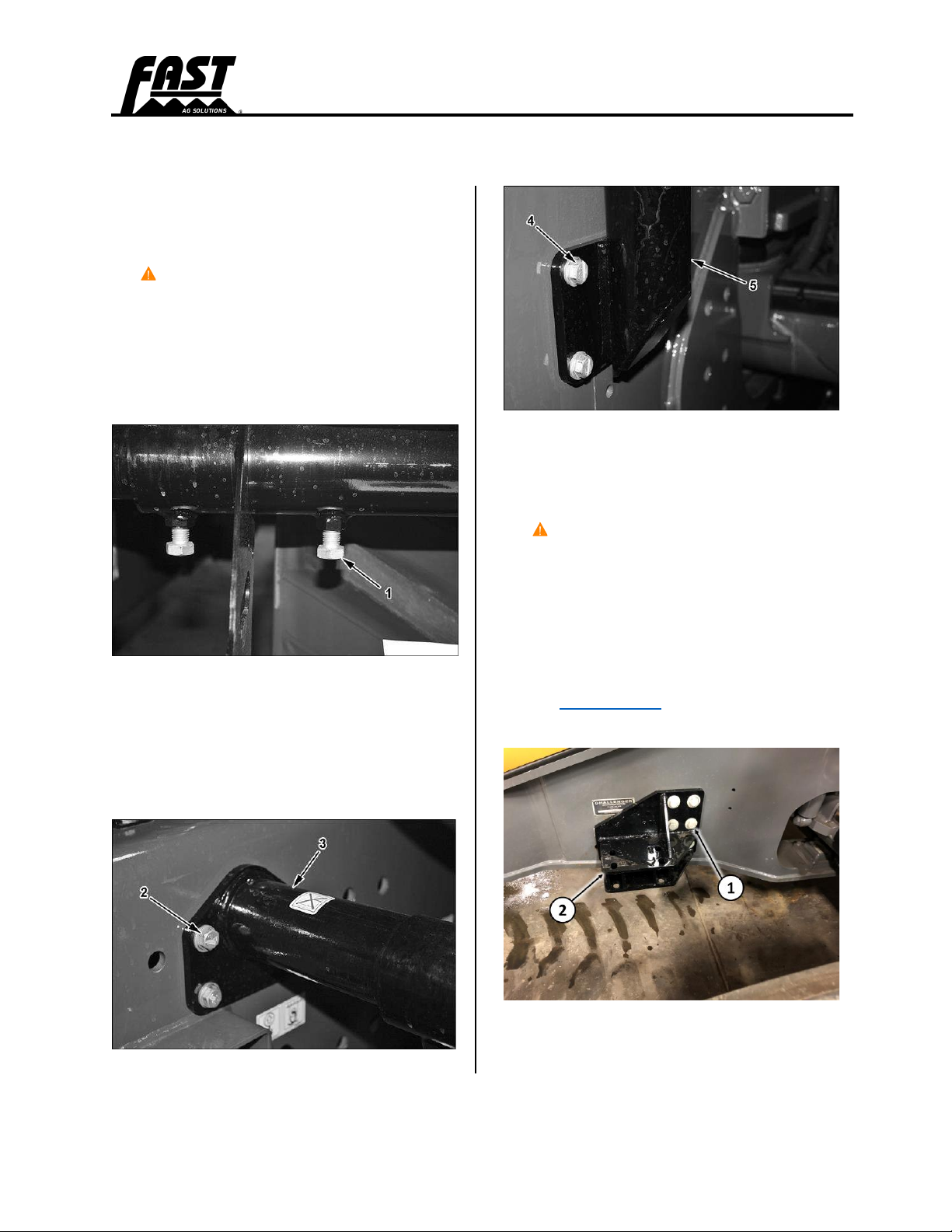
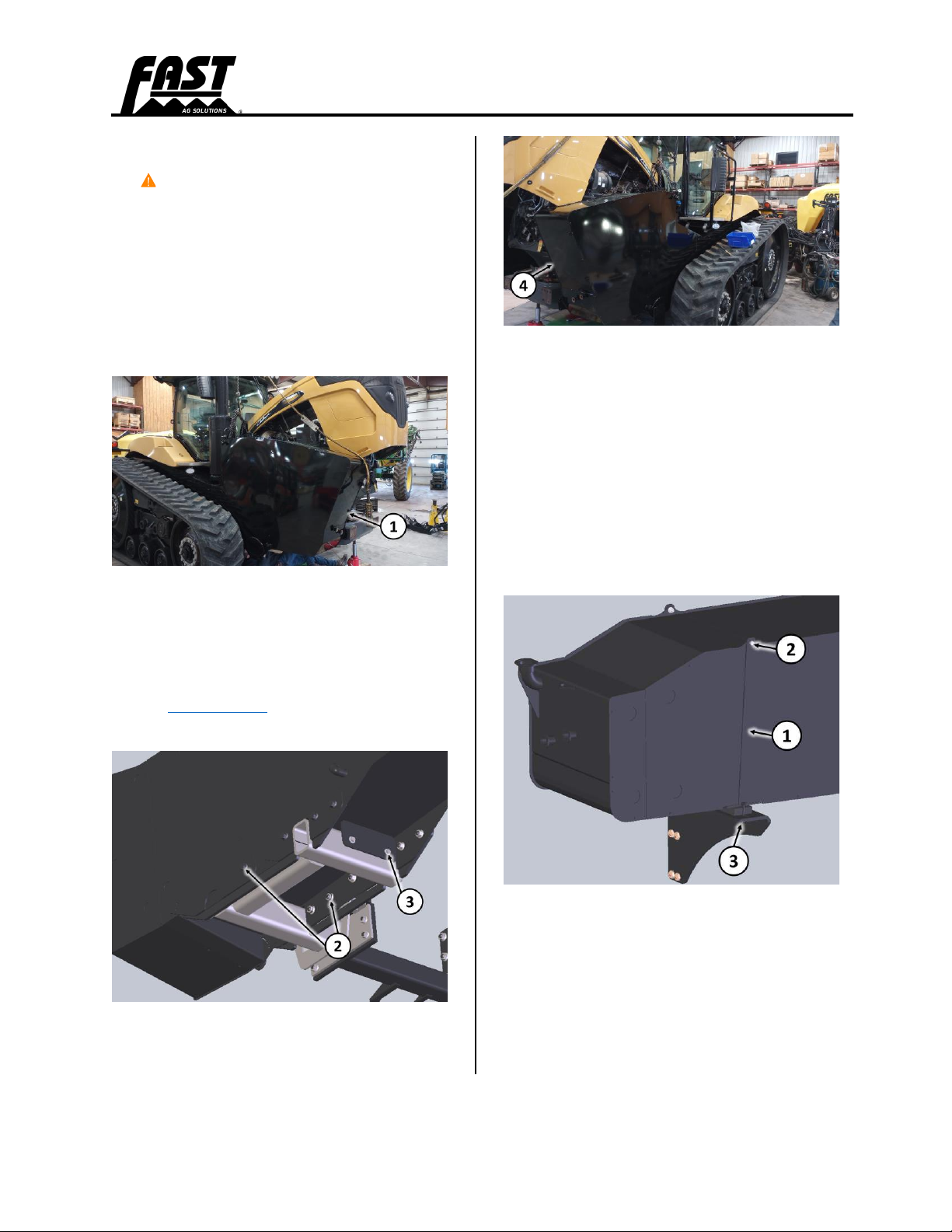
1. Loosen the four bolts (1) holding the
step assembly to the support tube.
2. Attach a lifting device to the step
assembly.
3. Remove the step assembly.
4. Remove the four bolts (2) and lower
step tube (3). Discard the tube and its
hardware.
Install Receiver Mounting
Brackets
WARNING: Mounting bracket
weighs approximately 75 lbs. Use
an appropriate lifting device to
prevent injury.
1. Install the left-side mounting bracket
(1) on the tractor with 3/4” x 2” GR8
bolts (2) and flange nuts. Refer to the
torque charts in this Manual for bolt
torque values.
2. Repeat Step 1 with the right-side
mounting bracket (3).

INSTALLATION & PARTS
INSTALLATION Track Tank MT765 Challenger Page 10
3. Place the rubber isolators (4) on the
top and bottom of the bracket.
4. Place the plate (5) on top of the
isolator and insert four 3/4” x 9” GR5
bolts (6) through the plate and both
isolators.
5. Repeat Steps 3 and 4 for the left-
hand side receiver mounting bracket.
WARNING: Receiver mounting
tube weighs approximately 150
lbs. Use an appropriate lifting
device to prevent injury.
6. Raise the receiver mounting tube (7)
into position with the radar bracket to
the rear and install eight center-lock
nuts (8).
7. Tighten all eight bolts equally (1/8” –
1/4”) so some bulge is seen on the
rubber isolators.
Install Underside Supports
WARNING: Frame bracketry
weighs approximately 300 lbs. Use
an appropriate lifting device to
prevent injury.
1. Install the right-hand underside
support (2) onto the receiver
mounting bracket (1) with four 3/4” x
2-1/2” GR8 flange bolts (3) and
flange nuts and four 3/4” x 2” GR8
flange bolts (4) and flange nuts. Refer
to the torque charts in this Manual for
bolt torque values.
2. Repeat the procedure for the left-
hand side.

INSTALLATION & PARTS
INSTALLATION Track Tank MT765 Challenger Page 11
Install Radar
1. Attach the radar (3) to its mounting
bracket (1) with existing hardware
(2).
Install Rear Tank Supports
1. Install the right-hand tank mount (1)
with three M16 x 40mm GR8.8 flange
bolts (2). Refer to the torque charts in
this Manual for bolt torque values.
2. Install the rubber isolator (3) with
three 1/2” x 1-3/4” bolts (4), 1/2”
washers, and center-lock nuts. Snug
the bolts to slightly compress the
rubber.
3. Repeat the procedure for the left-
hand side.
INSTALLATION & PARTS
INSTALLATION Track Tank MT765 Challenger Page 12
Install Tanks
WARNING: Each tank weighs
approximately 1100 lbs. Use an
appropriate lifting device to
prevent injury.
1. Connect an appropriate lifting device
to the right-hand tank.
2. Raise the tank (1) and guide it into
position onto its support bracketry.
3. Align the tank receiver with the
underside support and install ten 3/4”
x 2” GR8 flange bolts (2) with flange
nuts and two 1/2” x 5-1/2” bolts,
washers, and nuts (3). Refer to
torque charts in this instruction set for
bolt torque values.
4. Repeat the procedure with the left-
hand tank (4).
5. Disconnect the lifting devices.
Install Straps and Nylon
Protector
1. Position the straps (1) into place and
insert its studs through the holes in
the tank supports. Install one each
3/8” x 1” G5 bolts and nuts (2) and
1/2” flange nut (3).
2. Repeat the procedure on the left-
hand side.

INSTALLATION & PARTS
INSTALLATION Track Tank MT765 Challenger Page 13
Install Step Assembly
WARNING: Step assembly weighs
approximately 300 lbs. Use an
appropriate lifting device to
remove step assembly.
1. Install the top bracket platform (1)
onto the tractor above the left-hand
tank with existing hardware (2).
2. Install the base step (3) with four 5/8”
x 2” GR8 flange bolts and flange nuts
(4). Refer to torque charts in this
instruction set for all bolt torque
values.
3. Attach a lifting device to the step
assembly.
4. Install the step assembly (5) as
shown into its receiver and tighten its
setscrews (6).
5. Install the barrier chain between the
step assembly and existing platform’s
rails.


INSTALLATION & PARTS
PARTS Track Tank MT765 Challenger Page 20
Parts List 35500: Tanks & Plumbing
ITEM
PART
QTY
DESCRIPTION
1
15566
1
SPACER, HOSE BRACKET
2
25027
1
BRACKET, VALVE MOUNT
3
34901
1
WELDMENT, RH TANK
4
34949
1
WLDMNT, RH FRONT MNT
5
34954
1
WLDMNT, CENTER TUBE
6
34957
1
WLDMNT, LH FRONT MNT
7
34964
1
WLDMNT, LH TANK
8
35104
1
ASSY, BARRIER CHAIN
9
35148
2
PLATE, FRONT BOLT
10
35149
4
RUBBER, FRONT ISOLATOR
11
35180
1
WLDMNT, REAR LADDER
12
35190
2
ASSY, SS RISER
13
35195
1
WELDMENT, FRONT LADDER
14
35196
1
BUMPER, REAR TANK
15
35197
4
WLDMNT, TANK HOLDDOWN
16
35199
1
RUBBER, RH TANK BUMPER
17
35236
1
PLATE, LH REAR SUPPORT
18
35237
1
PLATE, RH REAR SUPPORT
19
35298
1
WELDMENT, CENTER SUPPORT
20
35299
1
WELDMENT, CENTER SUPPORT R
21
35413
1
FENDT RADAR BRACKET/DEFLECTOR
22
500009
2
VALVE, 1.00 FULL PORT SINGLE UNION
23
500065
2
TEE, .50 MPT X .50 HB
24
500075
1
VALVE, 1.00 MANIFOLD, 3-WAY BOTTOM LOAD
25
510003
33 FT
HOSE 2" FERTILIZER
27
510006
20 FT
HOSE VINYL CLEAR 3/4 IN
28
510012
16 FT
HOSE 1/2 IN EPDM
29
510016
34 FT
HOSE, 1 IN EPDM
37
530019
11
GASKET, 2.00 EPDM
38
530035
3
STRAIGHT, 1/2 MPT 1/2" HB
39
530041
2
FITTING, 1.00 MNPT X 1.00 HB, POLY
40
530043
4
FITTING, 1.00 MPT X .75 HB
Table of contents
Other Fast Farm Equipment manuals


Popular Farm Equipment manuals by other brands


Agria
Agria Cyclone 5900 Translation of the original operating instructions

Vicon
Vicon Fanex 1134 T Assembly instructions

SCHMOTZER
SCHMOTZER Venterra 2K KPP-LSC Translation of the original operating instructions

Kemper
Kemper 460plus Operator's manual

LEMKEN
LEMKEN EuroDrill Instruction book

FARMTECH
FARMTECH T-DCBM-4 user manual