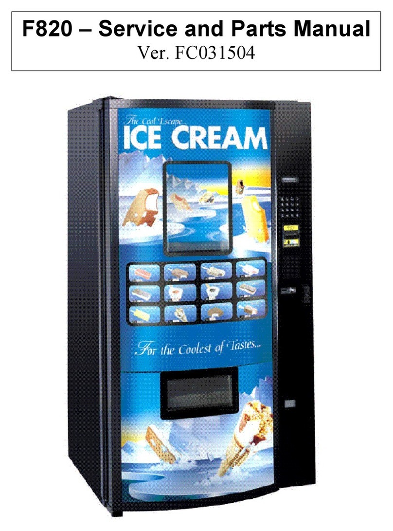
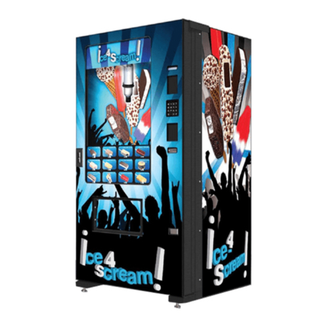
Fastcorp FRI-Z400 User manual

FRI-Z400 ICE CREAM MACHINE
INSTALLATION & SET-UP GUIDE
VERSION 20060508
FOOD AUTOMATION SYSTEMS AND TECHNOLOGIES
60 East Hanover Ave. B2
Morris Plains, NJ 07950
Tel: (973) 455-0400
Fax: (973) 455-7401

FASTCORP (“SELLER”) TERMS AND CONDITIONS OF SALE
1. PRICES. All prices, quotations, shipments and deliveries by Seller are F.O.B. Seller's facility. All base prices are subject to change upon thirty (30) days notice and all orders
are accepted subject to Seller's price in effect at the time of shipment.
2. APPLICABILITY, ACCEPTANCE AND MODIFICATION. These terms and conditions apply to all quotations and purchase orders covering the sale of Seller's products or
services. Seller's acceptance of Buyer's order is expressly made conditional on Buyer's acceptance of the terms and conditions set forth herein. The terms and conditions set
forth herein constitute the complete agreement between the Seller and the Buyer, and may be accepted only in accordance with their terms. They may not be modified except by
written agreement referring specifically to these terms and conditions and signed by a duly authorized officer of Seller. Any provisions of Buyer's purchase order which are
inconsistent with the foregoing shall be of no force and effect, unless Seller shall have agreed to a modification of these terms and conditions in the manner set forth herein.
Buyer's failure to dissent from the terms and conditions, or Buyer's acceptance or use of the Seller's equipment shall constitute Buyer's acceptance of these terms and conditions.
Buyer, by these presents and the acceptance of the goods ordered herein represents and warrants the Buyer is solvent and able to pay for the goods in accordance with these
terms and conditions of sale. Any order accepted by Seller shall not be assigned, sold or otherwise transferred by Buyer unless Seller expressly agrees in writing to such sale,
assignment or other transfer.
3. DELIVERY AND DELAYS. Seller's obligation is to deliver the goods F.O.B. Seller's facility. Risk of loss passes to Buyer at the moment of delivery. Buyer will inspect the
products within a reasonable time after receipt thereof and if Buyer fails to notify Seller within thirty days after receipt that the products are defective in any respect, Buyer will
have waived any rights or claims against Seller. Orders for products made to Buyer's specifications are not subject to cancellation by Buyer. Products made to Buyer's
specifications must be inspected and accepted by Buyer before shipment. After shipment, Buyer shall have no rights or claims against Seller for such products. Delivery dates
appearing on Seller's order acknowledgment, or given to Buyer in any other manner, are approximate. Seller will not be liable for any delay in the performance hereof or for any
damages suffered by Buyer by reason of such delay it caused or by the occurrence of any contingency beyond the control of Seller including, but not limited to, delays or
nondelivery arising directly or indirectly from fires, floods, substantial damage to its plant, accidents, riots, acts of God, open hostilities, declarations of national emergencies,
war, terrorist acts, governmental interference or embargoes, strikes, labor difficulties, shortage of labor, fuel, power, materials or supplies, or any other cause or causes (whether
or not similar in nature to any of those herein above specified) beyond its control. Seller shall allocate production and deliveries among Seller's customers in its sole discretion.
4. STORAGE. In the event that Buyer is unable to accept delivery of parts or equipment at the time of completion and of shipment, Seller may invoice for the total purchase
price as if the shipment has been made and; (i) if Seller is able to store such equipment in its own facilities, the Buyer shall pay Seller reasonable handling and storage charges
for the period of such storage; or (ii) if Seller is unable to store such equipment in its own facilities, Seller reserves the right to arrange handling and storage in a suitable
warehouse for the Buyer, at the Buyer's expense. In cases where handling and storage become necessary, it will become the responsibility of the Buyer to notify Seller when
shipment is to be made and to what destination.
5. ADEQUATE ASSURANCES. Seller may, at any time, suspend performance of any order or require payment from Buyer in cash, security or other adequate assurance
satisfactory to Seller when, in Seller's sole opinion, the financial condition of Buyer or other grounds for insecurity warrant such action.
6. TAXES. Any tax which the Seller may be required to pay or collect, through assessment or otherwise, under any existing or future law upon or with respect to the sale,
purchase, delivery, transportation, storage, processing, use or consumption of any goods or services provided by Seller to Buyer, including taxes upon or measured by the
receipts from sales or services, shall be for the account of Buyer and may be added to the price of goods or services purchased by Buyer. Buyer shall promptly pay the amount
thereof to Seller upon demand.
7. LIMITED WARRANTY.
(A). Subject to the limitations specified herein, the Z-400 Frozen Merchandiser manufactured by Seller is warranted for two (2) years from the date of purchase against
defective parts and workmanship and the Z-400 Frozen Merchandiser's freezer system consisting solely of the compressor, condenser, evaporator and the refrigerant tubing is
warranted for two (2) years from the date of purchase against defective parts and workmanship. Any part or parts which are proven to be defective within the applicable
warranty period will be repaired and/or replaced free of charge, provided that, (i) the return of such part or parts is authorized in writing by Seller's Warranty Department (the
"Return Authorization"), and (ii) the defective part and a copy of the Return Authorization is returned with transportation charges prepaid to the destination designated by
Seller's Warranty Department. All labor charges shall be for the account of Buyer.
(B). The warranties provided pursuant to Section 7(A) apply only to the original purchaser of the Z-400 Frozen Merchandiser and are null and void if the Z-400 Frozen
Merchandiser is sold during the period of warranty.
(C). Notwithstanding anything contained herein to the contrary, the limited warranties provided for herein do not apply to: (i) electrical components, wiring, or circuits
and/or for all mechanical parts or assemblies damaged as a result of operating the Z-400 Frozen Merchandiser at other than 115 volts, 60 Hertz current; (ii) incandescent lamps,
neon lamps, fluorescent lamps, ballasts, starters, bins and associated components, graphics or other expendable items; (iii) when other manufactured components are installed by
Buyer in the Z-400 Frozen Merchandiser; and (iv) coin mechanisms, bill validators, currency systems, telemetry systems, cashless payment systems, debit card readers, and
other accessories not manufactured by Seller installed at Buyer’s request.
(D). Seller is not responsible for any cost of service rendered or repairs made by buyer or its agents on merchandise or parts unless authorization to incur expense has been
given in writing by Seller prior to incurring such expense.
(E). Seller shall not be liable to Buyer under this warranty if Seller determines that the defect was caused by misuse, abuse, vandalism, improper application, improper
operation, improper maintenance, alteration, repair or modification, negligence or use, casualty, fire, flood, storage, handling or any other cause beyond the control of Seller.
(F). THE WARRANTIES PROVIDED FOR UNDER THIS SECTION 7 ARE EXCLUSIVE AND IN LIEU OF ALL OTHER WARRANTIES, OBLIGATIONS OR
LIABILITIES. SELLER EXPRESSLY DISCLAIMS AND BUYER HEREBY WAIVES ALL OTHER WARRANTIES, EXPRESSED OR IMPLIED, INCLUDING
WITHOUT LIMITATION, WARRANTIES OF MERCHANTABILITY OR FITNESS FOR A PARTICULAR PURPOSE. THE BUYER ACKNOWLEDGES AND AGREES
THAT NO OTHER REPRESENTATIONS OR WARRANTIES WERE MADE TO OR RELIED UPON BY BUYER WITH RESPECT TO THE QUALITY AND FUNCTION
OF THE GOODS SOLD HEREIN. SELLER DOES NOT AUTHORIZE ANY PERSON, COMPANY OR ENTITY WHATSOEVER TO ASSUME FOR IT ANY
OBLIGATION OR LIABILITY IN CONNECTION WITH THE SALE OF SAID EQUIPMENT OR ANY PART THEREOF.
8. LIMITATIONS OF BUYER'S REMEDIES. Buyer's remedies with respect to any claim arising out of any order, or Seller's performance in connection therewith,
including, without limitation, any claim arising out of any defect or alleged defect in any goods or services furnished by Seller, shall be limited exclusively to the repair
and replacement of defective parts as specified in Section 7 herein. Without limiting the foregoing, Seller shall not be liable for breach of contract arising out of or in
connection with a warranty claim. In no event shall Seller be liable for any damages including, but not limited to, lost profits or other incidental or consequential
damages arising out of this agreement or the use or inability to use any of the products including, but not limited to, the Z-400 Frozen Merchandiser, even if Seller has
been advised of the possibility of such damages, or of any claim by Buyer or any other party.
9. WAIVER. Waiver by Seller of any breach by Buyer of any of the terms and conditions set forth herein shall not be construed as a waiver of any other breach or the failure of
Seller to exercise any right arising from any default of Buyer hereunder shall not be deemed to be a waiver of such right, which may be exercised at a subsequent time.
10. GOVERNING LAW. This Agreement shall be governed by the Uniform Commercial Code as adopted by the State of New Jersey in force as of the date hereof. Buyer
consents to the jurisdiction of the state and federal courts within the State of New Jersey. Service of process by certified or registered mail shall be sufficient to commence suit
and obtain a judgment by default. Buyer waives any right to personal service of process. Notwithstanding anything contained herein to the contrary, if Seller so directs, any
controversy or claim arising out of or related to this agreement or the performance or breach thereof shall be resolved by binding arbitration in accordance with the rules and
procedures then obtaining of the American Arbitration Association. Any action or proceeding by Buyer arising out of or in connection with this transaction, including any claim
for Seller's breach of contract or Seller's breach of Warranty, must be commenced within two (2) years after the delivery of the equipment to Buyer except in the case of a claim
for Seller's breach of Warranty relating to the Z-400 Frozen Merchandiser's freezer system as provided for herein which must be commenced within five (5) years after the
delivery of the equipment to Buyer.
11. Credit. All invoices paid after the due date specified within shall accrue interest at the lesser of 2% per month or the highest rate of interest permitted by law. In the event
that the Buyer pays any invoice with a credit card, Buyer hereby waives, releases, and discharges any all rights that Buyer may have, under the terms of Buyer's agreement with
the credit card provider, to dispute, challenge and/or protest the payment of any Seller invoice.
TABLE OF CONTENTS
I. SPECIFICATIONS………………………………..……………………………………………………………….
A. General Safety Specifications..………………………………………………………………………..…….
B. Tool Listing..………………………………………………………………………..………………………….
C. General Specifications & Measurements.…………………………………………………….…………....
II. PRODUCT IDENTIFICATION…….……………...………………………………………………..…………….
A. Serial Number…..…………..……………………………………………….………………..………………
B. Model Number…..…………..……………………………………………….………………..……………...
III. UNPACKING & INSTALLATION…..………….…………………………………………………..……………
A. Receiving Inspection...……………………………………………………………………………..….……..
B. Unpacking...…………………………………………………………………………………………………...
C. Removing The Cable Ties & Shipping Bracket…………………………………………………………...
D. Transport Instructions…….....………………………………...……………………..………………………
E. Leveling the Machine...………...…………………………………………………………..………………...
F. Electric Power Requirements...……………………………………………………….…………………….
G. Grounding the Machine……...……………………………………..……………………………………..…
IV. GENERAL MAINTENANCE & CLEANING…..………….……………………………………………………..
A. Lubrication…..………….…………………………..………….…………………………..………….………
B. General Cleaning Considerations…..………….…………………………..……………….………………
C. Freezer Maintenance...……………………………………………………………………………………...
V. SETUP INSTRUCTIONS………………………………….……………………….………….………………...
A Money Systems………………………………….……………………….………….……….
1. Types of Money Interface Systems………………..………………………………...……....…..….…
2. DEX Port………………………………….……………………….………….…………………………..
3. Installing Peripherals…………………………………………………………………………………….
4. Coin Mechanism………………………………….……………………….………….………………….
5. Bill Acceptor………………………………….……………………….………….……………………….
6. Card Readers………………………………….……………………….………….……………………..
B Initial Power Up (Homing Sequence)…………………………………………….…………………………
C Product Display System (w/ Price Tag Template)……………………………...………………………..
D Bin Setup/ Product Loading ………………………………….……………………….…………………….
1. General Considerations………………………………….……………………….…………………….
2. Bin Setup Plan-O-Gram………………………………….……………………….……………………..
3. Product Loading Considerations…...……………………….……………………….…………………
4. Bin Selection & Modification Considerations………………………………….………………………
5. Price List Reference Sheet…………………….……………………….………………………………
E Preprogramming Configuration………………………………………..……………………………......….
1. Control Board Dip Switch Options (Clearing Memory)…...……….……………………….…………
F Programming……………………………………………………………..……………………...………....…
1. Introduction (Programming Menu Summary)………...……..………………………….…..….…..…
2. Getting started /Creating Selections..…………………………………………………..…………..…
3. Programming/Editing After The Machine Has Been Operating…………………………………….
4. Programming Bin Floor Height…………………………..……………………………………………..
3. Menu Items/ Programming Sequence…………………………..……………………..…………..….
a. Change Price…………………………………..……………………………………….………...…
b. Sales Meters………………………………..………………………………………….……..…..…
c. Resetable Meters………………………………..…………………….……………………..…..…
d. Edit Selection………………………………..…………………..…………...………………..….…
e. Create Selection…………………………………………………………………...…………..……
f. Delete Selection………………………………..………………………….………………..………
g. Selection #s..…………..………………………………….……………………….……..…………
h. Set Date…..…………..………………………………………………………….…………..………
i. Set Time…..…………..………………………………………………………….………………….
j. Set Service Phone #…..…………..………………………………………………………….……
k. Sales Pin Code…..…………..………………………………………………………….…………
l. Vend Block…..…………..………………………………………………………….……………….
m. VB PIN Code…..…………..………………………………………………………….…………….
n. Health Timer…..…………..………………………………………………………….…………….
A-1
A-1
A-1
A-1
A-2
A-2
A-2
A-3: A-5
A-3
A-3
A-4
A-5
A-5
A-5
A-5
A-6
A-6
A-6
A-6
A-7: A-29
A-7
A-7
A-7
A-7
A-7
A-8
A-9
A-10: A-11
A-12: A-16
A-12
A-13
A-14
A-15
A-16
A-17
A-17
A-18: A-29
A-18
A-19
A-20
A-20
A-21: A-29
A-21
A-21
A-21
A-22
A-23
A-24
A-24
A-24
A-24
A-25
A-25
A-25: A-26
A-26
A-26

TABLE OF CONTENTS
F. Programming (Continued) …………………..………..……………………….…………………...…….…
3. Menu Items (Continued) …………………………..………………………….…….…..…..……….…
o. Program Version…..…………..………………………………………………………….………….
p. Display Language…………………………………………………………...……...…………….…
q. Line Mode….……………………..……………………………………..….…………….……….…
r. Machine Serial Number……………………...……………..……………….……..…………….…
s. Group Sales Option…..…………………..…………………………………..……….………….…
t. Tokens & Coupons…………………………..…………………….………………………..…….…
u. Field Test…..………………………..………………………..……………………..….…..…….…
v. Viewing Freezer Temperature….……..………………………..……….……..…………………..
w. Testing Considerations…..……………….………………………………………………………….
VI. COMPONENT REFERENCE AND IDENTIFICATION.……………………………………………………….
A. Cabinet Assembly…….………………………….………………………….………………………….……
B. Fan Assembly…….………………………….………………………….……………….……………………
C. Inner Door Assembly…….………………………….………………………….………………………….…
D. Power Box Assembly…….………………………….………………………….………………………….…
E. Computer Board…….………………………….………………………….………………………….………..
F. Triac Board…….………………………….………………………….………………………….……………..
G. Service Keypad…….………………………….………………………….………………………….………...
H. Robot Carriage-Rack Assembly…….………………………….………………………….…………………
I. Rack/Beam Assembly…….………………………….………………………….………………………….…
J. Robot Carriage Assembly…….………………………….………………………….………………………..
K. Picker Assembly…….………………………….………………………….………………………….………
L. Lid Lift Assembly…….………………………….………………………….………………………….……….
M. Valve Box Assembly…….………………………….………………………….………………………….…..
A-18: A-29
A-21: A-29
A-26
A-26
A-27
A-27
A-27
A-28
A-28
A-29
A-29
A-30: A-40
A-30
A-30
A-31
A-32
A-33
A-33
A-34
A-34
A-35: A-36
A-37
A-38
A-39
A-40

GENERAL SAFETY SPECIFICATIONS
Please read this manual in its entirety. This service information is intended for use by a qualified service techni-
cian, familiar with the proper safety and service procedures. Before repairing, replacing, or adjusting any FAST-
CORP machine components, the qualified service technician should be equipped with the proper tools and/or re-
placement components, using genuine FASTCORP factory parts.
!!WARNING!! ALL ADJUSTMENTS, ASSEMBLY, AND REPAIRS MUST BE PERFORMED IN ACCORDANCE
WITH FASTCORP INSTRUCTIONS AND SAFETY PROCEDURES. PERSONS ATTEMPTING TO SERVICE THE
MACHINE WITHOUT PROPER TRAINING MAY SUBJECT THEMSELVES TO HAZARDS SUCH AS ELECTRICAL
SHOCK, CAUSING SERIOUS INJURY OR DEATH.
ALWAYS POWER DOWN AND UNPLUG THE MACHINE WHEN SERVICING ANY AND ALL ELECTRICAL AND
MOVING COMPONENTS.
Only use a dedicated 115V 15 Amp electrical power supply with ground to power the machine. Lower volt-
age may result in vacuum related problems and/or improper coin acceptance.
!!WARNING!! TO ENSURE SAFETY AND PROPER OPERATION, THE MACHINE MUST BE PROPERLY
GROUNDED. IF THE GROUND STATUS OF AN OUTLET CANNOT BE READILY DETERMINED OR VERIFIED
BY THE FACILITY, HAVE IT CHECKED BY A LICENSED ELECTRICIAN. DO NOT REMOVE THE GROUND PIN
OR IN ANY WAY BYPASS, MODIFY, DEFEAT, OR DESTROY THE GROUNDING SYSTEM OF THE MACHINE.
EXTENSION CORDS OR POWER STRIPS MUST NOT BE USED TO SUPPLY POWER TO THE MACHINE.
Stay clear of the cabinet interior when power is on and the door is open. Moving robotic components may cause
head or body trauma if a person comes within the path of the robot. Refrain from standing inside or near the front
of an open cabinet while the robot attempts to dispense product. When vending product, the robot accelerates to-
wards the front center section of the cabinet known as the “Drop Point”.
MEASUREMENT SPECIFICATIONS
TRANSPORT CONSIDERATIONS
Always try to keep the FRI-Z400 in the upright position. If the machine must be laid down for delivery purposes, be
sure the machine is upright for at least 24 hours before it is plugged into an outlet and powered. This will give the
compressor fluid time to re-settle in the freezer compressor. Failure to do so can damage the compressor and
void the warranty.
Whenever the FRI-Z400 is moved or transported, always use the shipping brackets provided when the machine
was first delivered and new tie wraps. Refer to the uncrating instructions for tie wrap and shipping bracket installa-
tion.
SPECIFICATIONS
GENERAL ELECTRICAL
HEIGHT:
WIDTH:
DEPTH:
WEIGHT:
72.0 in./182.9 cm.
37.0 in./93.98 cm.
36.0 in./91.44 cm.
604-lbs./273.97 kg.
VOLTAGE:
FREQUENCY:
AMPERAGE:
AMP DRAW:
110-115 A/C
60 Hz
8.9 Amps.
2.5 Amps resting /9 Amps operating
A-1
General listing of Tools, Equipment and/or Supplies that May be Required When Installing or Servicing Machine
(Refer to manual for details under each specific heading)
Installation or Transport:
Pallet Jack/Dolly or Forklift, Cutting Pliers, Phillips Screwdriver,
Flathead Screwdriver, 11/32” Deep Socket, 3/8” Socket, 7/16”
Socket, 1 1/2” socket , Bin Plan-O-Gram, Product with Product
Listing and Pricing, Product Cards and Price Tags, Peripheral
devices (Coin Mech.), Coins, Level, Original Transport Brack-
ets, Cable Ties, Protective Packaging Materials, Tape (low re-
sidual adhesive to secure freezer lid), Appropriate Power Sup-
ply
Maintenance & Troubleshooting:
Cutting Pliers, Phillips Screwdriver, Flathead Screwdriver, Needle
Nose Pliers, 11/32” Deep Socket, 3/8” Socket, 7/16” Socket, 1/4”
Socket, 7/64” Allen Wrench w/ 8” T-handle, Bin Plan-O-Gram,
Product Listing and Pricing, Volt Meter, Replacement Parts and
Corresponding Tools, 15 Amp Fuses

PRODUCT IDENTIFICATION
SERIAL NUMBER
The production date of this FASTCORP product is determined by the date code incorporated in the serial number.
The vender serial number takes the form XXXXYYYYZZ. The first 4 digits (XXXX) identify the manufacturing run that
the vender was built in. The next 4 digits (YYYY) identify the specific machine.
The last 2 digits (ZZ) indicate when the machine was produced. The first digit indicates the quarter and the second
indicates the year.
Example:
69640043 AC
In this example, this was machine number 43 in production run 6964 and was built in the first quarter (A) of 2004
MODEL NUMBER
The model number, FRI-Z400-AAB, is broken down as follows:
First Digit (quarter) Second Digit (Year)
A = 1st Quarter C = 2004
B = 2nd Quarter D = 2005
C = 3rd Quarter E = 2006
D = 4th Quarter F = 2007
1st digit F = FASTCORP
2nd digit R = Robotic
3rd Digit S = Snack or I = Ice Cream
4th thru 7th digits = Model number
8th digit = Series A = 1st series
B = 2nd series
C = 3rd series
9th digit = Electrical A = 110 volt
B = 220 volt
10th Digit = Color B= Black
A-2

UNPACKING & INSTALLATION
(A copy of these instructions are attached to the front of the machine)
This machine has been packed in order to protect its internal components during transportation and distribution.
FASTCORP has also made unpacking and installation a quick and easy process. FASTCORP recommends the fol-
lowing steps be taken when unpacking the machine.
!!WARNING!! DO NOT PLUG IN THE MACHINE UNTIL ALL STEPS ARE COMPLETED IN
THIS SECTION. THE RETAINING BRACKETS AND THE TWO CABLE TIES MUST BE RE-
MOVED BEFORE POWERING UP THE MACHINE TO AVOID DAMAGE TO SENSITIVE
MECHANISMS.
RECEIVING INSPECTION
Upon receipt, remove packing materials from the exterior of the machine, shrink wrap, fiberboard edge protectors and
corrugated front protector from the outside of the vender. Store the fiberboard edge protectors and corrugated front
protectors for future transport use. Inspect the vender for any external or internal shipping damage. If there is any
damage, have the driver note the damage on the bill of lading and notify FASTCORP. Although the terms of sale are
FOB shipping point, which requires the consignee to originate shipping damage claims, FASTCORP will gladly help if
you must file a claim. Close the door and tighten the lock.
REMOVE SHRINK WRAP FROM CABINET PRIOR TO STORING VENDER OUTSIDE.
UNPACKING THE VENDER
Remove the shipping boards from the bottom of the vender. The shipping boards are attached to the leveling legs. To
avoid unnecessary damage to the leveling legs or base, remove shipping boards using a 1½ inch socket type wrench
and unscrew the leveling legs. Be sure to replace the legs after removing the shipping boards. Store the shipping
boards so that they can be reused anytime the machine is moved. Once the vender is unpacked, check the service
area for any additional parts, price/product labels, service/operation manual, or other information concerning factory
equipped accessories such as coin and bill acceptors.
REMOVING THE CABLE TIES & SHIPPING BRACKET:
Remove the shipping bracket from the Robot by unscrewing the (3) 1/4 X 20” bolt with a wrench and the cable ties
from the picker and robot assemblies. Refer to the following pictures for the locations of the cable ties. Store the
bracket and screws at the base of the door for future use. Finally, remove tape on freezer lid and chest.
MACHINE MUST BE UNPLUGGED!
REINSTALL ROBOT RETAINING BRACKET AND CABLE TIES WHENEVER
TRANSPORTING MACHINE.
A-3
Fig. 1
(Robot Carriage-Rack Assembly & Hose System)
REMOVE SHIPP ING
BRACKET
CUT CABLE TIE
CUT CABLE TIE

TRANSPORT INSTRUCTIONS (CHANGING VENDER LOCATIONS)
1. Before re-securing internal components for transporting, turn the machine off. This will disable passive braking
and allow the robot to be moved manually.
2. Unplug the main power cord from the wall and attach the cord to the plastic hook or tape to the back of the cabi-
net. This prevents the power cord from being damaged when the unit is moved.
3. Empty all money from the coin mechanism and bill acceptor. Remove the coin mechanism and bill acceptor (if
necessary). (Steps 3 - 8 can be performed at the warehouse. Steps 6 – 8 must be performed less than 12 hours
after the machine is turned off.)
4. Remove the lock cylinder from the T-handle assembly (if necessary).
5. Make sure that the customer (product) delivery bin is empty and clean.
6. Remove all bins and bin matrix pieces from the inside of the freezer. Remove all product from the bins and return
all frozen product to the frozen truck/warehouse. Wipe down the inside and outside of each bin and all matrix
pieces.
7. Defrost the freezer. Remove the inside and outside drain plugs and let any water run into a bucket in front of the
freezer. Wipe the inside of the freezer down and clean any melted ice cream or debris from the inside of the
freezer. Additional water or soapy water solution may be required to completely clean the freezer. Use paper
towels to dry the inside of the freezer.
8. When the freezer is clean and dry, reinstall the ice cream bins and matrix. Replace any damaged or dirty bins.
9. Center the robot in the cabinet so that the robot-retaining bracket can be screwed on using the three 1/4 –20 hex
bolts set aside in the cabinet door (refer to UNPACKING AND INSTALLATION). The robot-retaining bracket se-
cures the robot beam to the trolley plate preventing it from moving left to right. Two bolts are screwed into the top
of the cabinet and one bolt is screwed into the side of the robot.
10. Match up the T-slots located on the right side of the robot carriage and robot cover (see UNPACKING AND IN-
STALLATION). Create a loop with the cable tie, insert through the T-slots, and tighten the cable tie. This cable
tie secures the robot carriage to the robot beam preventing it from moving front to back.
11. A second cable tie is inserted into the slot on the robot located next to the picker head. Make sure that the picker
head is fully retracted and insert the cable tie through the slot and around the base of the picker above the suction
cup (see Unpacking and Installation Instructions). Tighten the cable tie once the picker is secure.
12. Secure the Freezer Lid to the Freezer chest with tape (with low residual adhesive such as masking tape) to pre-
vent if from vibrating open.
1. Make sure that the Inner Door is fully closed and has latched. Close the main outer door and screw in the T-
Handle until the door is completely closed and secure.
14. Re-install the shipping boards to the bottom of the machine. Make sure that the leveler legs are screwed into the
boards to firmly hold the boards in place.
15. Use cardboard or appropriate packing materials to protect the corners of the machine. Cover the machine with
shrink-wrap or other protective material to prevent surface scratches or damage.
16. Move the machine using a pallet jack or forklift, taking care to always pick up the machine from the back. If the
machine must be turned on its side refer to TRANSPORT CONSIDERATIONS.
NOTE: IF ANY OF THE RETAINING BRACKET(S), CABLE TIES, OR SHIPPING BOARDS ARE MISSING,
PLEASE CONTACT THE FASTCORP PARTS DEPARTMENT TO PURCHASE REPLACEMENTS. IF THERE
ARE ANY QUESTIONS REGARDING THESE INSTRUCTIONS, PLEASE CALL THE FASTCORP TECHNICAL
SERVICE DEPARTMENT AT 1 (888) 441–3278.
The vender must be located on a solid, flat, and level surface. Make sure the flooring can bear the weight load of
a fully stocked vender. The vender must be positioned close enough to an electrical outlet so that an extension
cord is not required. If the machine will be subject to user misuse or vandalism, it is recommended that the vender
be secured to the floor or wall. Please contact FASTCORP Technical Service Department for more information.
Due to the large size and weight of the vender, never attempt to move the vender with a hand truck or stair
climber. The vender should be moved with a Pallet Jack or Vender/Cooler Dolly at all times. The vender should
never be slid or pushed in place. Never side load the leveling legs, doing so will damage the legs.
A-4

ELECTRIC POWER REQUIREMENTS
Refer to pg. 1, GENERAL SPECIFICATIONS for the proper voltage and frequency requirements (domestically this
requirement is 115 Volts, 60 Hertz). The cabinet serial plate also indicates the Amperage of the vender. The vender
must be plugged into its own properly rated single phase, alternating current outlet with its own circuit protection
(fuse/circuit breaker).
DO NOT USE AN EXTENSION CORD OR POWER STRIP TO SUPPLY POWER TO THE MACHINE.
GROUND THE VENDER
The vender is equipped with a three wire power supply cord and MUST be plugged into a properly grounded outlet. If
the outlet will not accept the power cord plug, contact an electrician to install a proper AC outlet.
DO NOT REMOVE THE GROUND PIN OR IN ANY WAY BYPASS, MODIFY, DEFEAT, OR DESTROY
THE GROUNDING SYSTEM OF THE VENDER.
FAILURE TO COMPLY WITH THESE INSTRUCTIONS MAY SUBJECT THE USER TO THE RISK OF INJURY OR
ELECTRICAL SHOCK WHICH CAN BE SERIOUS OR FATAL.
A-5
LEVELING THE MACHINE
!!DANGER!! THE VENDER MUST BE PROPERLY LOCATED AND LEVELED. IF THE
MACHINE WILL BE SUBJECT TO USER MISUSE OR VANDALISM, IT IS RECOM-
MENDED THAT THE VENDER BE SECURED TO THE FLOOR OR WALL TO MINIMIZE
RISK OF INJURY OR DEATH FROM TIPPING. CALL THE FASTCORP TECHNICAL SER-
VICE DEPARTMENTAT (888)441-3278 FOR ASSISTANCE.
Adjust the front leveling legs, to level the cabinet front-to-rear then adjust the front and rear legs an equal number of
turns to level left to right. A carpenter’s level placed on top of the machine (front to back & left to right) will help verify
that the machine is level. Leveling legs are adjusted using a wrench or socket 1-½ inches in size. Lowering the legs
will raise the machine approximately 1/4” per 4 turns. If the machine is to be used next to another vender, check the
top and side for proper alignment. Minimum leg extensions should be used in leveling and alignment to attain greater
stability. Make sure that all the leveling legs are in contact with the floor. If you cannot level the vender, select another
location. Do not place any objects under the machine. Leveling is extremely important to ensure proper vender opera-
tion. Do not program or operate the machine before the leveling process I complete. If preprogramming selections in
a warehouse prior to placement, the machine must be leveled again at the new location and all the program selec-
tions checked for proper robot-bin alignment.
POSITIONING THE MACHINE
Do not block the rear of the vender. Keep the vender 4 inches (10 cm) from the wall to ensure adequate ventilation
airflow. At the front of the vender, make sure that nothing obstructs the air intake at the bottom of the service door
and cabinet. At the rear of the vender, make sure nothing obstructs the air exhaust at the bottom of the cabinet.

GENERAL MAINTENANCE & CLEANING
LUBRICATION
Do not use oil or other lubricants on any moving parts. Application of these substances will cause damage to com-
ponents.
GENERAL CLEANING CONSIDERATIONS
It is important to maintain the machine in accordance with this manual in order to facilitate proper air flow within the
vender and to prevent the opportunity for insects and rodents to infiltrate the cabinet.
To allow for proper air flow, the fan located in the lower-right corner of the cabinet should be cleaned using a cloth at
regularly scheduled intervals. Those intervals will be dictated by the cleanliness of the location and the amount of
airborne contaminants, however, all machines should be cleaned at least once per month.
DISCONNECT POWER PRIOR TO SERVICING ANY ELECTIRCAL OR MOVING COMPONENTS (INCLUDING
FAN). DO NOT PULL ON WIRES THAT SUPPLY POWER TO ANY COMPONENTS. FAILURE TO COMPLY MAY
RESULT IN DAMAGE TO THE VENDER AND INCREASED RISK OF ELECTRIC SHOCK.
TO AVOID THE POSSIBILITY OF A FIRE HAZARD AND TO DECREASE THE POSSIBILITY OF RESTRICTED AIR-
FLOW INTO THE VENDER, DO NOT STORE ANYTHING OR ALLOW DEBRIS OF ANY KIND TO ACCUMULATE
AT THE BOTTOMOF THE DOOR, AT THE BOTTOM OF THE SERVICE AREA OR IN FRONT OF THE FANS.
Do not use water, soap or any other liquid to clean inside the machine. The outside of the cabinet can be cleaned of
fingerprints and debris by using a soft cloth with a mild detergent. Never use flammable materials to clean the cabi-
net interior or exterior as damage to the vender’s finish may occur.
FREEZER MAINTENANCE
Viewing freezer temperature: while in Vend Mode (indicated by “Please Insert Money” on the digital display),
press the “*” key on the Customer Keypad. The current temperature will be displayed on the digital display.
Two or three hours after powering up the machine, the freezer temperature should drop until it is between –15ºF/-26ºC and –20ºF/-
28ºC. Any temperature adjustment can be made using the thermostat, located in the upper back right side of the freezer. The
freezer is set for -20ºF/-28ºC and may be adjusted using a standard screwdriver. Turn the screwdriver clockwise for colder and
counter-clockwise for warmer. The range of operation temperature is –25ºF/-31ºC to 15ºF/-9ºC (at 70ºF/21ºC ambient).
4 HOURS AFTER INSTALLATION, CHECK AND ADJUST THE THERMOSTAT SO THAT THE FREEZER MAINTAINS
A RECOMMENDED TEMPERATURE RANGE OF –15ºF/-26ºC TO –20ºF/-28ºC
The standard chest freezer inside the FRI-Z400 does not self-defrost automatically. The freezer chest requires maintenance when
ice begins to affect the vend cycle, product loading, or the closing of the freezer door. The refrigeration system does not require
any maintenance. Depending on the location’s moisture level (relative humidity) and frequency of operation, ice deposits will occur
primarily around the top three to four inches of the freezer. It is not necessary to defrost the freezer every time there is ice build up.
Ice can be chipped away as long as it does not make its way down along the walls or underneath the bins. Excessive ice build-up
may require bin removal. The freezer does not have to be unplugged to perform this process.
FASTCORP recommends keeping a plastic ice scraper (provided with the machine), and a 9” by 11” piece of cardboard or plastic
inside the machine. Place the plastic under the area to be scraped to prevent the ice from falling into the bins. This entire process
should only take a few minutes.
Depending on usage, temperature and humidity, a full cleaning may be necessary. First, press the load button then power down
the machine. Remove all the bins and the bin matrix. Next, place the ice cream in a holding container. Scrape the ice and remove
it from the basin. To rinse out the freezer chest, place a drain pan under the drain and remove the drain plugs. One is located on
the inside left of the freezer and the other on the outside lower left (a standard screwdriver might be necessary). Finally, reload the
old bins or replace with new ones. Turn on the machine and run each selection to make sure the bins did not shift or were put in
the wrong location. The freezer will take about 2-4 hours to get down to temperature.
Under normal conditions, the FRI-Z400 can be unplugged with the door closed for up to 12 hours without harming the product. If
freezer temperatures reach unsafe levels, the health sensor will activate and the machine will be placed out of order. Your product
must be discarded and proper cleaning procedures must be taken.
The screen will read “Health Sensor Active”. The machine will not operate until both the RESET button is pressed and the
freezer temperature has returned to safe levels. The machine is set not to accept money if the freezer has not reached proper op-
erating temperatures. If the machine must be operated for test purposes, the heath sensor can be bypassed even though the
freezer is not at an acceptable temperature. This is covered in the following section “PROGRAMMING / MENU ITEM PRO-
GRAMMING SEQUENCE / HEALTH TIMER”. A-6

SETUP INSTRUCTIONS
MONEY SYSTEMS
TYPES OF MONEY INTERFACE SYSTEMS
This machine supports ONLY 24-34 Volt MDB (Multi-drop Bus) Money systems
This machine is compatible with any MDB compliant (level 2 and higher) coin mechanism and bill acceptors as
well as several of the most common card readers. If you wish to utilize one or more of these devices, please con-
tact FASTCORP Technical Support for questions on compatibility.
(Note: The machine is not compatible with the COINCO 9302GX Coin Mechanism)
DEX PORT
The FRI-Z400 comes pre-wired for a DEX port located on the inside of the main door. To collect DEX data, insert the
DEX plug into the 1/4 phone jack and pull out the vend service interlock switch located adjacent to the T-handle be-
hind the main door. The vender must be in Vend Mode with display reading- “Please Insert Money”.
INSTALLING PERIPHERALS
Coin and currency acceptors as well as card readers or other MDB peripherals should be installed and their function
tested prior to placing the vender in service. Always power down (left toggle switch on power box) before plugging or
unplugging peripherals.
COIN MECHANISM
When installing a coin mechanism, make sure that all 3 mounting screws are tightened. Fill the coin tubes to the
proper levels then power up vender and pull the door switch plunger out. Test the operation of the Coin Mechanism
by inserting the required amount of change into the slot on the front of the vender. If the display reads “machine must
be set up,” program at least one selection then test coin mechanism for proper operation. While testing, push the
coin return button after inserting one or two coins to verify coins are returned to the change cup. If coins are not re-
turned or if the return lever gets stuck, refer to the adjustment procedure below.
1. Remove power to the vender
2. Place the coin mechanism to be used in position and secure it
to the access door.
3. Loosen the two 8-32 x 3/8 (A) screws that secure the VRV
coin return plunger to the VRV coin return rocker.
4. Lower the VRV coin return plunger to the coin mechanism’s
reject lever and tighten the two 8-32 x 3/8 screws (A).
5. With the door open, test the VRV coin plunger assembly for
proper operation.
Note: If the VRV coin return plunger shifts out of position
behind the coin mechanism’s reject lever, place the VRV
coin return back to its proper position and adjust the 10-
32 x 1 ¼ screw (B) to prevent this from occurring.
6. Once adjusted to the acceptable position, plug in the vender,
close the main door and secure it. Place coins in the coin in-
sert from the front of the vender to test for proper operation.
Note: If coins fall directly into the change cup, the VRV
coin return plunger is adjusted too low.
A-7
Fig. 2

BILL ACCEPTOR
Remove the lower block-off plate from the door by removing the four #8 nuts with an 11/32 nut driver and the two
ground wires from the bottom left stud. Install the bill acceptor on the studs then, using the nuts removed above; se-
cure the bill acceptor to the door. After the bill acceptor is mounted, the two ground wires must be re-installed to
the stud from which they were removed. Tighten all four nuts to secure the entire assembly, then power up vender
and test for proper operation.
Note: The coin mechanism must be installed with coins in the coin tubes and at least one selection
must be programmed in order to test bill acceptor function. Please refer to the programming section
for more information on how to program vender.
CARD READERS
There are many card readers and similar devices available. FASTCORP has tested many of these devices in order
to ensure compatibility with our software. Occasionally, there will be a new product introduced into the market which
may require further testing to ensure correct compatibility. In most cases there are no issues so long as the periph-
erals are of level 2 or higher MDB specifications. If you have any difficultly with peripherals that you are using,
please call FASTCORP Technical Service.
A card reader can be installed directly above the bill acceptor in the upper most access hole. The access hole will
have a block-off plate preinstalled from the factory and must be removed prior to installation of the card reader. Re-
move the four #8 nuts on the back of the plate using a 11/32 nut driver.
A-8

INITIAL POWER UP
Make sure that the shipping bracket and cable ties are removed from the robot before plugging the machine into the
power source. To avoid the risk of injury, make sure that all body parts are clear of the cabinet before turning on the
main power. The Main Power Switch is located on the Power Box, under the freezer.
The robot should follow the initial power-up homing sequence:
1. Robot picker head moves UP.
2. Robot carriage moves towards the CENTER of the cabinet.
3. Robot carriage moves towards the FRONT of the cabinet (considered the HOME position).
If the robot does not move or follow the power-up homing sequence:
1. There may be setup errors or shipping damage. Review all the previous sections and check for errors on the
display. Press the # key for diagnosis.
2. Check the transformer reset breaker and make sure the power switch is on (refer Fig. 3 below).
3. Perform a quick check to see if there are obstructions preventing the robot from moving freely on all axes.
a. Power the machine off to disable “dynamic breaking” features that make it hard to move the robot
manually.
b. Manually move the robot to the left, right, front and back. Check for smooth travel. Note any ob-
struction or gear binding.
A-9
Fig. 4
(Homing Sequence/Robot Carriage-Rack Assembly)
1. UP
2. CENTER
3. FORWARD
Fig. 3
(Homing Sequence/Robot Carriage-Rack Assembly)
CONTROL BOARD
POWER SWITCH LIGHT
SWITCH VACUUM BREAKER
10 AMP MAIN POWER: (MAIN POWER SWITCH ALLOWS THE
FREEZER TO REMAIN ON INDEPENENTLY)
MAIN
BREAKER
15 AMP
TRANSFORMER RESET ACCESS
HOLE SNAP PLUG REMOVED
TRANSFORMER RESET

A-10
PRODUCT DISPLAY SYSTEM
1. Determine what products will be vended and locate the corresponding display card provided by the manufacturer.
2. Affix the correct price label to the front of the card using the template provided on the next page. Make a copy
and attach to the inside of the machine for future use.
3. Open the main cabinet door and locate the Inner Door Latch to open the Inner Door.
4. Every card slot on the product display sheet has 4 card holder tabs located at each corner. Secure each product
card by inserting the corners of the card into the card holder tabs (with product cards facing forward).
INNER DOOR LATCH
INNER DOOR
Tabs
CARD HOLDER SHEET
CARD IN CARD SLOT CARDS IN CARD
HOLDER (FRONT VIEW)
PRODUCT CARD TABS
OPEN INNER DOOR
Fig. 5
Fig. 6

A-11
3.025"
5.900"
0.50"
2.25"
2.00
PRODUCT DISPLAY SYSTEM CONTINUED-
Use the template provided to attach the price label to the Product Cards. If price labels are attached correctly, they
will be visible to the right of the selection numbers on the front of the machine door once the once the cards are in-
stalled.
PRICE TAG LOCATION
USE THIS DIAGRAM AS A TEMPLATE TO LOCATE
THE PRICE TAG ON THE PRODUCT CARD
NOTE: FOR USE WITH .88”W X .50”H SELF ADHESIVE BACK TAGS
PRODUCT DISPLAY CARD
Fig. 7

BIN SETUP / PRODUCT LOADING
The FRI-Z400 utilizes a bin system to hold product. The bin system is made up of a number of bins (various shapes
and sizes), held together by a plastic bin matrix. The type and size of bin used depends on the size and shape of the
product being vended. Every machine comes pre-configured with a specific bin layout or “Bin Plan-o-gram”.
Note: Please refer to the Bin Layout Guide (accompanying this manual) for plan-o-grams and instructions
GENERAL CONSIDERATIONS
1. To keep track of products in a bin configuration, we recommend that the plan-o-gram form be filled out and at-
tached to the inside of the machine. The product name, price and bin number can also be written directly on
each bin. In addition, the computer is programmed to leave one product at the bottom of each bin allowing prod-
ucts to be matched by the service person for refilling.
2. Always keep a copy of each machine’s specific bin plan-o-gram at a remote location (office) as a reference and
backup copy.
3. Each bin size comes in two different bin heights: tall and short. Short bins are approximately ½ the size of the tall
bins and are located on the right side of the chest freezer above the compressor. In a typical configuration, there
are a total of four short bins. Short bins do not have to be programmed as menu selection and can be used for
product overflow or storage.
4. Always load product from the bottom-up (so that product will be vended with the freshest at the bottom and the
oldest on top. FIFO: First In, First Out).
5. The standard bin configuration holds a majority of all ice cream novelties. Spacers and inserts are provided for
products such as ice cream cones, sandwiches and Snickers™ . However, if there are products that require spe-
cial bins, contact the FASTCORP service dept. for alternative bin shapes and spacers. When reordering bins, re-
fer to the bin part numbers detailed in the machine’s bin plan-o-gram.
6. Always keep an extra set of bins and a plastic bin matrix on hand in the event of a meltdown. Bins can be re-
moved quickly and new bins can easily be installed.
7. There should not be more than a 1/4 inch gap between the product and bin in any direction. Use smaller bins or
the proper spacers to ensure product retrieval.
8. FASTCORP recommends placing the best selling items at the center of the freezer. This shortens the distance
the robot must travel, reducing vend cycle time.
A-12

A-13
Fig. 8 Plan-O-Gram (Aerial View)
Note: When programming, it is important to program the bin selections located at the back right and the front right corners as short bins; the rest are tall bins. If
short bins are programmed as tall bins, the robot will make contact with the bottom of the bins and attempt to pull them out, resulting in possible machine failure
(out-of-order). If tall bins are programmed as short bins, the machine will only vend product based on the height of a short bin. The robot will leave product at the
bottom of the tall bin and flag it Out-Of-Product. Refer to PART:A GENERAL INFORMATION, PRODUCT LOADING and PROGRAMMING sections.
BIN SETUP/ PLAN-O-GRAM

Fig. 9 Product Loading Example (w/Cone Bins)
BIN LOADING CONSIDERATIONS
A-14
PRODUCT MUST ALWAYS BE LEVEL IN BINS (ALTERNATE PRODUCT DIRECTION WHEN LOADING CONE BINS)

BIN SELECTION & MODIFICATION CONSIDERATIONS
Fig. 10 Examples Of Bin Spacer Configurations (Aerial View)
ALWAYS USE THE CORRECT BIN AND BIN SPACER FOR A PRODUCT.
WHEN SELECTING A BIN OR MODIFYING A BIN WITH BIN SPACERS, MAKE SURE THAT THE BIN IS NOT TOO TIGHT WHERE
PRODUCT CAN GET STUCK AND THAT PRODUCT CANNOT MOVE MORE THAN ¼ “ ON ANY GIVEN SIDE.
CONE SPACERS SNICKERS SPACERS BOMBPOP SPACERS
Refer to PART:A GENERAL INFORMATION, PRODUCT LOADING and PROGRAMMING sections.
A-15

Fig. 11 Price List Reference Sheet (Fill Out and Keep A Copy In Each Machine For Reference)
A-16
SHORT SHORT
SHORT
SHORT
MACHINE SN: LOCATION NAME:
Table of contents
Other Fastcorp Vending Machine manuals
Popular Vending Machine manuals by other brands

SandenVendo
SandenVendo Snack Safety Point SVE SSP Programming manual

Intralot
Intralot OHIO MPNG manual

N&W Global Vending
N&W Global Vending Colibri Quick reference guide

Cartadis
Cartadis CMDB Guide

Automatic Products
Automatic Products PREMIER 937 SATELLITE Setup and installation

damian
damian LXS9 Series Installation and service