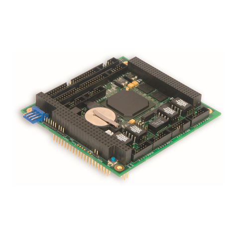
CPC316
C P C 3 1 6 U s e r M a n u a l 2 ©2021 F a s t w e l V e r . 0 0 2
List of Tables
Table 1-1: Terminal board TIB972-01 (Talbe of pins).......................................................................................14
Table 1-2: Requirements for the external power supply parameters................................................................15
Table 1-3: Purpose of the power supply connector pins...................................................................................15
Table 1-4: Purpose oft he pins of RS-422/485 (XP8, XP4) ports......................................................................22
Table 1-5: Configuration of the COM3 (X6) port...............................................................................................22
Table 1-6: Configuration of the COM4 (X7) port...............................................................................................22
Table 1-7: Purpose of the pins of RS-232 (XP13, XP14) ports.........................................................................24
Table 1-8: Frequency divider values for serial ports.........................................................................................25
Table 1-9: Purpose of pins of the USB (XP19) ports........................................................................................26
Table 1-10:Purpose of pins of the LAN1 (XP10) port ........................................................................................27
Table 1-11:Purpose of pins of the LAN2 (XP15) port ........................................................................................27
Table 1-12: Binding levels of UNIO ports lines (X20) ……………………………………………..………………….29
Table 1-13: Purpose of the pins of DIO (UNIO IO_A[23:0], XP16) connector ……………….………………….….29
Table 1-14: Purpose of pins of the DIO (UNIO IO_B[23:0] , XP18) connector …………………………………..…30
Table 1-15: Purpose of the VGA port pins (XP2) ………………………………………………………………..…….31
Table 1-16: Purpose of LVDS (XP3) port pins …………………………………………………....…………..…….….31
Table 1-17: Purpose of Audio ports pins (XP17, XP6)………………………………….…………………………..…32
Table 1-18: Purpose of XS1 connector pins: PC/104 (ISA 8/16-bit) rows A, B …………………………………….32
Table 1-19: Purpose of XS1 connector pins: PC/104 (ISA 8/16-bit) rows C, D ………………………………….…33
Table 1-20: Purpose of XS2 connector pins: PCI/104 (PCU 32-bit) rows A, B ………………………………….....34
Table 1-21: Purpose of XS2 connector pins: PCI/104 (PCU 32-bit) rows C, D …………………………...……..…35
Table 1-22: Purpose of device LEDs……………………………………………... …………………………………….36
Table 1-23: Purpose of pins of XP9 indication connector ………………………………………………………….…36
Table 1-24: Purpose of ADC channels ADC_AUX [7:0]…………………………………………………………….....38
Table 1-25: Purpose of GPIO (XP1) port pins …………………………...……………………………………...…..…38
Table 2-1: Addresses of hardware interrupts …………..……………………... …………………………………….40
Table 2-2: DMA channels of the device …………………………………………………………………………….…41
Table 2-3: Distribution of I/O address space ……………………………………………………………………….....41
Table 2-4: Addresses of memory devices …………...…………………...………….………………………...…..…42
Table 2-5: GPIO control registers …………..……………………………………………………………………….....42
Table 2-6: Purpose of GPIO ports …………...…………………...………….……………………….………...…..…43
Table 2-7: WDT0 restart register …………...……………………………………………………………………….....44
Table 2-8: Index register of the WDT0 port address …………...…………………...………….……………………44
Table 2-9: Data register of the WDT0 port …………..……………….…………………………………………….....44
Table 2-10: Register of WDT0 timer control…....…………………........…….……………………….………...…..…45
Table 2-11: Register of WDT1 event selection ……..……........…………………………...……………………….....45
Table 2-12: Register CNT0 of the WDT0 timer value ………..…...……………..…...………….………….....…..…45
Table 2-13: Register CNT1 of the WDT0 timer value …....…………………........…….………………....…...…..…46
Table 2-14: Register CNT2 of WDT0 timer value ……..……........………………………..……………………….....46
Table 2-15: WDT0 timer state register ………..…..........................……………..…...………….………….....…..…46
Table 2-16: WDT1 restart register …………………..…....…………………........…….………………....…...…..…46
Table 2-17: WDT1 timer control register ……..……........…………...……………………..……………………….....47
Table 2-18: WDT1 event selection register ………..……………....……………..…...………….………….....…..…47
Table 2-19: Register CNT0 of WDT1 timer value ………..…..........................……………...….………….....…..…47
Table 2-20: Register CNT1 of WDT1 timer value …....………..……………........…….………………....…...…..…48
Table 2-21: Register CNT2 of WDT1 timer value ……..……........………………………..……………………….....48
Table 2-22: WDT1 timer state register ………..…...…………………….………..…...………….………….....…..…48
Table 2-23: Table of external connections for “n00” firmware........................……………...….………….....…..…60
Table 2-24: Table of "p55" firmware registers …....………..……………........…….………..…………....…...…..…62
Table 2-25: External connections for the "p55" firmware ……..……........………………..……………………….....64
Table 2-26: External connections for the “c02» firmware ………..…...…………………….……………….....…..…68
Table 2-27: Ranges of the “q04” conditioner …....………..……………........……...………..…………....…...…..…71
Table 2-28: External connections for the “q04” firmware ……..……........………………..……………………….....72
Table 2-29: Table of external connections for “t00” firmware ………..…...…………….….……………….....…..…75
Table 3-1: Purpose of switches for device configuration ……..……........……….……..……………………….....76
Table 5-1: Description of the “Main” menu ………………….………..…...…………….….……………….....…..…84


