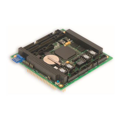
Fastwel KIC551 User manual

KIC551
Interface Module
in 3U CompactPCI Serial format
User Manual
Rev. 003
September 2021
The product described in this manual is compliant
with all related CE standards.

Product Title: KIC551
Document name: KIC551 User Manual
Manual version: 003
Ref. docs: -
Copyright © 2021 Fastwel Co. Ltd. All rights reserved.
Revision Record
Rev. Index
Brief Description
Product Index
Date
001
Preliminary version
KIC551/ KIC551RC
August 2017
002
Initial version
KIC551/ KIC551RC
November 2018
003
Compliance assessment
KIC551/ KIC551RC
September 2021
Contact Information
Fastwel Co. Ltd
Fastwel Corporation US
Address:
108 Profsoyuznaya st.,
Moscow 117437,
Russian Federation
6108 Avenida Encinas,
Suite B, Carlsbad,
CA92011, USA
Tel.:
+7 (495) 232-1681 Tel.:
+1 (858) 488-3663
Fax:
+7 (495) 232-1654
E-mail:
Web:
http://www.fastwel.com/

KIC551
K I C 5 5 1 U s e r M a n u a l 1 ©2021 F a s t w e l V e r . 0 0 3
Table of Contents
Table of Contents.....................................................................................................................................................1
List of Tables............................................................................................................................................................2
List of Figures .......................................................................................................................................................... 3
General rules of usage …...……………………………………………………………………………………….………….8
Manufacturer's warranties…………………………………………………………………………………………………….8
Transportation, Unpacking and Storage…………………………………………………………………………………..10
1Description and operation of KIC551/KIC551RC.............................................................................. 11
1.1 Purpose of KIC551/KIC551RC ................................................................................................................... 11
1.2 Technical specs of KIC551/KIC551RC ……………………………………………………………………………11
1.3 Structural features of KIC551RC……..……………………………………………………………………………13
1.4 Structure and functioning of KIC551/KIC551RC…………………………………………………………………13
1.5 Ordering information for KIC551…………………………………………………………………………………...13
1.6 Ordering information for KIC551RC…………………………………………………………………………….…14
1.7 Location of components and overall dimensions of KIC551……………………………………………………15
1.8 Location of elements and overall dimensions of KIC551RC……………………………………………………19
1.9 Delivery checklist of KIC551/KIC551RC………………………………………………………………………….21
1.10 Packaging information………………………………………………………………………………………………22
2Description and operation of subsystems of KIC551/KIC551RC ................................................... 23
2.1 Block diagram............................................................................................................................................. 23
2.2 Description and operation of functional nodes............................................................................................ 24
2.3 Description of KIC551/KIC551RC module’s units …..…………………………………………………………...25
2.4 Cooling system of KIC551………………………………………………………………………………………….37
2.5 Cooling system of KIC551RC ……………………………………………………………………………………..38
3Intended Use........................................................................................................................................ 39
3.1 Power consumption of KIC551/KIC551RC ................................................................................................. 39
3.2 Compliance with safety requirements of KIC551/KIC551RC...................................................................... 40
3.3 Electromagnetic compatibility of KIC551/KIC551RC .................................................................................. 40
3.4 Operating conditions of KIC551…………………………………………………………………………………….40
3.5 KIC551RC operating conditions…………………………………………………………………………………...41
3.6 Cooling system requirements ……………………………………………………………………………………...41
3.7 Installation and removal …………………………………………………………………………………..............43
3.8 Battery replacement ………………………………………………………………………………………………...47
4Program configuration of KIC551/KIC551RC ................................................................................... 51
4.1 Modification of operating software.............................................................................................................. 51
4.2. Upgrading configuration software via Gigabit Ethernet interface of the KIC551/KIC551RC module ..…....54
ANNEX A: List of FPGA internal function registers ……..…………………………………………………………..………78
ANNEX B: List of Telnet Interface Commands ………………………………………………………………………..………80
ANNEX C: Characteristics of the peripherals’ clock signals……………………………………………………….……….81
ANNEX D: Characteristics of the Gigabit Ethernet unit switch ……..……………………………………………..………82
ANNEX E: Characteristics of the output stage of AFBR-810 Avago Transmitter and input stage of AFBR-820
Avago Receiver ……………………………………………………………………………………………………………………..83
ANNEX F: List of compatible equipment …………………………………………………………..…………………..………85
ANNEX G: List of references and web resources ……..……………………………………………………………..………86
ANNEX H: DICSLAIMER…………………………………………………………………………………………………..……….87

KIC551
K I C 5 5 1 U s e r M a n u a l 2 ©2021 F a s t w e l V e r . 0 0 3
List of Tables
Table 1-1: Versions of KIC551..........................................................................................................................13
Table 1-2: Versions of KIC551RC ....................................................................................................................14
Table 1-3: Packed weight of KIC551 and KIC551RC.......................................................................................22
Table 2-1: Status of the HL13 LED...................................................................................................................30
Table 2-2: LED unit……………………………………………………………………………………………..……….31
Table 2-3: Status of PE1 –PE8 LEDs ………………………………………………………………………………...32
Table 2-4: Status of the ET1 –ET8 LEDs…………………………………………………………………………….32
Table 2-5: Status of SFP LED………………………………………………………………………………………….32
Table 2-6: Status of SYS LED………………………………………………………………………………………….33
Table 2-7: Status of FO LED……………………………………………………………………………………………33
Table 2-8: Status of OVH LED……………………………………………………………………………………….…33
Table 2-9: Status of UP LED……………………………………………………………………………………………34
Table 2-10: Purpose of the RJ45 Gigabit Ethernet connectors’ pins………………………………………………..36
Table 2-11: Transfer-Rate-and- Current-Consumption-Temperature-Relationship (KIC551) ………………….…38
Table 3-1: Paramters of KIC551/KIC551RC power consumtpion…………………………………………………..39
Table 3-2: Measurements results of starting current and average current consumption..................................39
Table 3-3: Paramters of climatic and mechanical effects (KIC551)..................................................................40
Table 3-4: Paramters of climatic and mechanical effects (KIC551RC).............................................................41
Table 3-5: Dissipated power and limit temperatures of microchips...................................................................42
Table 3-6: Temperature range (in the reference point of the heat removal plate of KIC551RC) ......................42
Table 3-7: Box of SA1 microswitches...............................................................................................................48
Table 3-8: Box of SA2 microswitches …………………………………………………………………………….…..49
Table 4-1: Purpose of register bits with the address 01 “EEPROM Control”……………………………………...55
Table 4-2: Compliance of bit sequences of the register with the address 01 “EEPROM Control” with the
selected EEPROM microchip ……………………………………………………………..………………………………………..56
Table 4-3: Register 03, Bit 0…………………………………………………………………...……………………….65
Table 4-4: Register 05, bit 0………………………………………………………………………..…………………..66
Table 4-5: Register 05, bit 1…………………………………………………………………………………………….66
Table 4-6: Register 05, bit 2….…………………………………………………………………………………………67
Table 4-7: Register 05, bit 3…………………………………………………………………………………………….68
Table 4-8: Register 05, bit 4…………………………………………………………………………………………….68
Table 4-9: Register 06, bit 0…………………………………………………………………………………………….69
Table 4-10: Register 06, bits 1 and 2……………………………………………………………………………………69
Table 4-11: Register 07….………………………….……………………………………………………………………70
Table 4-12: Main supply voltages ……………………………………………………………………………………….71
Table 4-13: Monitored temperature values……………………………………………………………………………..71
Table 4-14: Register 02…………………………………………………………………………………………………..72
Table 4-15: Register 00…………………………………………………………………………………………………..73
Table 4-16: Register 04…………………………………………………………………………………………………..73
Table 4-17: Sequence of bits of the system Program Configuration Unit…………………………………………...74
Table 4-18: Setting the values of prestart delay timer (byte 7 of system Program Configuration Unit)………….77

KIC551
K I C 5 5 1 U s e r M a n u a l 3 ©2021 F a s t w e l V e r . 0 0 3
List of Figures
Figure 1-1: KIC551-01.......................................................................................................................................15
Figure 1-2: Location of main components of KIC551, top view (as exemplified by KIC551-01).........................16
Figure 1-3: Front panel of KIC551-01................................................................................................................17
Figure 1-4: Front panel of KIC551-02................................................................................................................17
Figure 1-5: Overall dimensions of KIC551.........................................................................................................18
Figure 1-6: KIC551RC-01..................................................................................................................................19
Figure 1-7: Main components of KIC551RC front panel (as shown by KIC551RC-01)......................................20
Figure 1-8: Overall dimensions of KIC551RC....................................................................................................21
Figure 2-1: Block diagram for KIC551/KIC551RC..............................................................................................23
Figure 2-2: Diagram of the main units of KIC551/KIC551RC.............................................................................26
Figure 2-3: Diargam for multiplexing configuration EEPROM of KIC551/KIC551RC.........................................29
Figure 2-4: Location of H13 LED and power supply battery connector on KIC551/KIC551RC..........................30
Figure 2-5: Front panel LEDs ............................................................................................................................31
Figure 2-6: UP LED (GP LED)...........................................................................................................................34
Figure 2-7: RJ45 Ethernet Connector................................................................................................................36
Figure 3-1: Location of the reference point on the heat removal plate of KIC551RC.........................................43
Figure 3-2: SA1 and SA2 microswitches ...........................................................................................................48
All information in this document is provided for reference only, with no warranty of its suitability for any specific purpose. This information has been thoroughly checked and
is believed to be entirely reliable and consistent with the product that it describes. However, Fastwel accepts no responsibility for inaccuracies, omissions or their
consequences, as well as liability arising from the use or application of any product or example described in this document.
Fastwel Co. Ltd. reserves the right to change, modify, and improve this document or the products described in it, at Fastwel's discretion without further notice. Software
described in this document is provided on an “as is” basis without warranty. Fastwel assumes no liability for consequential or incidental damages originated by the use of
this software.
This document contains information, which is property of Fastwel Co. Ltd. It is not allowed to reproduce it or transmit by any means, to translate the document or to convert
it to any electronic form in full or in parts without antecedent written approval of Fastwel Co. Ltd. or one of its officially authorized agents.
Fastwel and Fastwel logo are trademarks owned by Fastwel Co. Ltd., Moscow, Russian Federation. CompactPCI is a trademark of the PCI industrial Computers
Manufacturers Group. Ethernet is a registered trademark of Xerox Corporation. IEEE is a registered trademark of the Institute of Electrical and Electronics Engineers Inc.
Intel is a trademark of Intel Corporation. Pentium M and Celeron M are trademarks of Intel Corporation. Microsoft is a trademark of the Microsoft corporation. In addition,
this document may include names, company logos and trademarks, which are registered trademarks and, therefore, are property of their respective owners.
Fastwel welcomes suggestions, remarks and proposals regarding the form and the content of this Manual.

KIC551
K I C 5 5 1 U s e r M a n u a l 4 ©2021 F a s t w e l V e r . 0 0 3
This User Manual (hereinafter referred to as the “User Manual” or “Manual”) is applicable to the
KIC551 interface module with forced cooling and KIC551RC interface module with conduction
cooling (hereinafter referred to as the device or KIC551/KIC551RC) and contains description,
principle of operation, technical specs of KIC551/KIC551RC, as well as establishes rules of its
operation.
You should read this User Manual before using the product.
The manufacturer shall not be liable for any potential loss or damages, caused by non-
compliance of recommendations and requirements given in this User Manual.
Attention!
All the operations with this device should be performed by trained engineers and technicians in
strict adherence to the instruction manuals.

KIC551
K I C 5 5 1 U s e r M a n u a l 5 ©2021 F a s t w e l V e r . 0 0 3
Ownership rights
This document contains information that is the property of Fastwel Group. It may not be copied or
transmitted by any known means, nor may it be stored in information storage and retrieval systems
without the prior written consent of Fastwel Group or one of its authorized agents. The information
contained in this document, to the best of our knowledge, is free from any errors, however, Fastwel
Group accepts no responsibility for any inaccuracies and their consequences, as well as liability
arising from the use or application of any diagram, product or example given in this document.
Fastwel Group reserves the right to change and improve both this document and the product
presented inside of it at its discretion without any further notice.
Safety requirements
This Fastwel Group’s product is developed and tested for the purpose of ensuring compliance to
the electric safety requirements. Its design provides long-term trouble-free operation. The service
life of the product can be significantly reduced due to the improper handling during unpacking and
installation. Therefore, in the interests of your safety and in order to ensure proper operation of the
product, you should follow the recommendations below.

KIC551
K I C 5 5 1 U s e r M a n u a l 6 ©2021 F a s t w e l V e r . 0 0 3
Conventions
Caution, High Voltage!
This sign and text warn of the dangers associated with electrical discharges (> 60 V)
when touching the device or any part of it. Failure to follow the precautions mentioned
or prescribed in the regulations may endanger your life or health, and may result in
damages to the equipment. Please also read the below subparagraph dedicated to the
rules for working with high voltage.
Attention! Static-Sensitive Device!
This sign and text indicate that the electronic boards and their components are
sensitive to static electricity, so proper care should be taken when handling this device
and performing inspections to ensure integrity and functionality of the device.
Attention! Hot surface!
This sign and text warn of the danger associated with touching hot surfaces of the
device.
Attention!
This sign is aimed at drawing your attention to aspects of this User Manual that, if not
fully understood or ignored, may endanger your health or cause damages to the
equipment.
Note
This sign is used to specify text fragments that should be read carefully.

KIC551
K I C 5 5 1 U s e r M a n u a l 7 ©2021 F a s t w e l V e r . 0 0 3
Safety requirements
This Fastwel Group product has been developed and tested to ensure compliance with electrical
safety requirements. Its design provides long-term fail-safe operation. The product's life cycle may
be significantly shortened due to mishandling during unpacking and installation. Therefore, for your
own safety and for ensuring proper operation of the device, you should follow the
recommendations given below.
Rules for safe handling with high voltage
Attention!
All the operations with this device should only be performed by personnel with sufficient
qualifications.
Caution, High Voltage!
Before installing the board in the system, make sure that the mains power supply is off. The same
also applies to the installation of expansion boards.
There is a serious risk of electric shock during installation, repairs, and maintenance of the device,
so always unplug the power supply cord while carrying out of works. The same also applies to the
other power supply cables.
Board Handling Instructions
Static-sensitive device!
Electronic boards and their components are sensitive to static electricity. Therefore, special
attention should be given when handling these devices to ensure their safety and operability.
Do not leave the board in the non-operating position without protective packaging.
If possible, always work with the board in workplaces protected against static electricity.
Should this not be possible, the user should remove the static charge before touching the product
with their hands or tools. The best way to do so is by touching any metal part of the system
enclosure.
Since the product is equipped with batteries to power the memory and real-time clock, avoid
placing the board on conducting surfaces such as anti-static mats or sponges. They can cause
short circuits and damage the battery and the board's conducting circuits.

KIC551
K I C 5 5 1 U s e r M a n u a l 8 ©2021 F a s t w e l V e r . 0 0 3
General rules of usage
In order to keep the warranty, the product must not be altered or changed in any way. Any
changes and improvements unauthorized by Fastwel Group other than those contained in this
User Manual or received from the technical support service of Fastwel Group in the form of a set of
instructions for their implementation will void the warranty.
This device should be installed and connected only to systems that meet all necessary technical
and climatic requirements. This also applies to the operating temperature range of a particular
version of the board. You should also consider the temperature limits of the batteries installed on
the board.
This device should be installed and connected only to the systems that meet all the necessary
technical and climatic requirements. This also applies to the operating temperature range of a
specific version of the module. Temperature limits of the batteries installed on the module should
also be considered.
Follow the instructions in this User Manual only when performing all necessary installation and
configuration operations.
Retain the original packaging for storing products in the future or to transport in case of a
warranty claim. If it is necessary to transport or store the board, pack it the same way as it was
packed at the time of receipt.
Proceed with extra caution when handling and unpacking the device. Follow the instructions in
the Chapter Transportation, Unpacking and Storage below.
MANUFACTURER’S WARRANTIES
Warranty liabilities
Fastwel Co. Ltd. (Fastwel), warrants that its standard hardware products will be free from defects
in materials and workmanship under normal use and service for the currently established warranty
period. Fastwel’s only responsibility under this warranty is, at its option, to replace or repair any
defective component part of such products free of charge.
Fastwel neither assumes nor authorizes any other liability in connection with the sale, installation
or use of its products. Fastwel shall have no liability for direct or consequential damages of any
kind arising out of sale, delay in delivery, installation, or use of its products.
If a product should fail through Fastwel's fault during the warranty period, it will be repaired free of
charge. For out of warranty repairs, the customer will be invoiced for repair charges at current
standard labor and materials rates.
Warranty period
The warranty period for the manufacturer's products is 36 months from the date of sale (unless
otherwise provided by the delivery agreement).
For customized products, the warranty period is 60 months from the date of sale (unless otherwise
provided by the delivery agreement).

KIC551
K I C 5 5 1 U s e r M a n u a l 9 ©2021 F a s t w e l V e r . 0 0 3
Limitation of warranty obligations
The above warranty does not apply to:
- the products (including software) that have been repaired or modified by the employees who do
not represent the Manufacturer. The exception is when the Consumer has made repairs or made
changes to the product strictly in accordance with the instructions previously agreed and approved
by the Manufacturer in writing;
- the products which have failed because of an inappropriate change of a polarity sign (to the
opposite one) of the power supply source, incorrect operation, transportation, storage, installation,
mounting or accident.
Procedure for returning products for repairs
Sequence of actions when returning products for repairs:
- contact the Product Manufacturer or Supplier for return material authorization for the product;
- attach to the returned product the fault identification report made in the form adopted by the
Consumer, indicating the list of circumstances and signs of malfunction;
- place the product in the consumer packaging of the Manufacturer (antistatic packaging) and
cardboard packaging (box)), in which the product was delivered to the Consumer. If there is no
antistatic packaging, the Consumer loses the right to warranty service unilaterally;
− the Consumer pays all the expenses related to the delivery of the product to the Supplier.

KIC551
K I C 5 5 1 U s e r M a n u a l 10 ©2021 F a s t w e l V e r . 0 0 3
Transportation, Unpacking and Storage
Transportation
The modules should be transported in the separate manufacturer’s packaging (container),
consisting of an individual antistatic packaging and a cardboard box, in closed transport (road, rail,
air in heated and sealed compartments) under storage conditions 5 according to the GOST
standard 15150-69 or under storage conditions 3 for sea transportation.
Transportation of packaged modules should be carried out in accordance with the rules of
transportation of goods currently valid for this type of transport.
During handling operations and transportation, the packaged modules should not be subjected to
sudden shocks, drops, impacts and precipitation. The packaged modules should be placed on the
vehicle in such a way as to preclude their further movements.
Unpacking
Before unpacking, after transportation at negative ambient temperatures, the modules must be
kept for 6 hours under storage conditions 1, in accordance with the GOST standard 15150-69.
Do not place the packed modules near any heat sources before unpacking.
When unpacking the modules, it is necessary to observe all precautions to ensure their safety, as
well as marketable condition of manufacturer’s consumer packaging.
When unpacking, it is necessary to check the modules for any external mechanical damages after
transportation.
Storage
Storage conditions of the modules 1 in accordance with the GOST standard 15150-69.

KIC551
K I C 5 5 1 U s e r M a n u a l 11 ©2021 F a s t w e l V e r . 0 0 3
1 Description and operation of KIC551/KIC551RC
1.1 Purpose of KIC551/KIC551RC
Names of the products described in this User Manual: KIC551 interface module (product
designation: IMES.421459.551) and KIC551RC interface module (product designation:
IMES.467449.003).
The KIC551 interface module is a high-speed programmable switch for PCI Express and Gigabit
Ethernet interfaces and is designed to transfer packets between peripheral slots and an external
device (see subparagraph 1.4).
The KIC551 is designed so as to provide consumers with an integrated 3U CPCI Serial solution for
the use in real-time systems, manufacture control, high-speed data acquisition and data
processing. KIC551 serves as an extension to the lineup of 3U CPCI modules manufactured by
Fastwel Group.
The KIC551RC interface module with a conduction-type cooler is based on KIC551 and is used for
building powerful special purpose ultra-reliable systems.
To remove heat from the KIC551RC, there is a specially designed heat removal cassette in
accordance with the CompactPCI Serial Mesh Backplane specification, PICMG 2.20 R 1.0.
Thereafter, the modules are named either as KIC551/KIC551RC or “the module”. In the text, where
it is necessary to indicate individual characteristics of the modules, it will be noted that we are
referring to the specific module version, and not to the module in general.
1.2 Technical specs of KIC551/KIC551RC
■PCIe Gen 3 interface:
▪Support of Peer-to-Peer and Multicast operation modes;
▪Possibility of slexible port configuration in х1, х4 and х8 modes;
▪Possibility of Upstream port switching;
▪Support of 54 x channel /12 ports PCIe Gen 2/3 switching;
▪ Switching of up to eight PCIe ports, routed to the backplane with PCIe optical port, routed to the
front panel.
■Fiber Optic (KIC551-01 and KIC551RC-01):
▪ bus width: 8 хPCIe;
▪ Support of GEN3 bandwidth (8 Gb/sec);
▪ MPO 12 Fiber 50um MMF cable connection (2 x cables);
▪ Maximum connection length: 50 m;
▪ Maximum Fiber Optic PCI Express connection rate: 64 GT/s*.
■1 Gbit Ethernet interface:
▪ Switching of 8 x 1000BASE-T channels, routed to the backplane with the 1000BASE-T port on
the front panel;
▪ Insulation strength: min. 100 V for channels, routed to the backplane;
▪ Insulation strength: min. 500 V for the channel, routed to the front panel.
■SFI 10 Gbit interface:
▪ Connection of SFP+ modules;
▪ Providing a high-speed data transmission channel.
________________________________________________
* Abbreviation that stands for “gigatransfers per second”

KIC551
K I C 5 5 1 U s e r M a n u a l 12 ©2021 F a s t w e l V e r . 0 0 3
■ STM32F207 integrated advanced ARM-based MCU (hereinafter referred to as the
microcontroller of MCU):
▪ Control of the supplied power;
▪ Support of the real-time clock;
▪ Managing the settings of optical modules;
▪ Acquisition and processing data from Hardware Monitor;
▪ Monitoring FPGA performance;
▪ Function of updating firmware for all integrated equipment, both in manual (via the Fast Ethernet
channel) and in automatic modes (according to a previously started algorithm).
■ Configuration FPGA:
▪ Control of the supplied power;
▪ Control of the managing MCU performance;
▪ Support of botting from the backup ROM in the event of WD-timer actuation;
▪ PCIe switch configuration and booting;
▪ Support of firmware update via the Ethernet channels;
▪ Indication of KIC551/KIC551RC performance.
■Supported standards:
▪ PICMG® CPCI-S.0 R1.0 March 2, 2011;
▪PCI Express® 3.0 specification;
▪PCI Express® External Cabling Specification Revision 1.0 January 4, 2007;
▪PCI Express® Base Specification Revision 2.0 December 20, 2006;
▪ SFF-8431 Specifications for Enhanced Small Form Factor Pluggable Module SFP+.
■ Power supply:
▪ Supply voltage: + 12 V, + 5 V_standby.
■ Operating temperature range of KIC551:
▪ Industrial version: from - 40 to +85 °C;
▪ Commercial version: from 0 to +70 °C.
■ Operating temperature range of KIC551RC:
▪ from -50 to +85 °C.
■ Humidity:
▪ up to 80%, non-condensing;
▪ up to 98%, non-condensing for \Coated option.
■ Resistance to vibration/single shocks/multiple shocks:
▪ 5 g/50 g/25 g (KIC551);
▪ 6 g/75 g/15 g (KIC551RC).
■MTBF:
▪ Min. 100,000 hours (KIC551);
▪ Min. 120,000 hours (KIC551RC).
■ Weight:
▪ Max. 0.65 kg (KIC551);
▪ Max. 1.0 kg (KIC551RC).

KIC551
K I C 5 5 1 U s e r M a n u a l 13 ©2021 F a s t w e l V e r . 0 0 3
1.3 Structural features of KIC551RC
The technical specifications for both KIC551 and KIC551RC are listed in subparagraph 1.2;
Features of the KIC551RC module are as follows:
▪ conduction heat removal cassette is used instead of the finned heatsink;
▪ KIC551RC correposnds to the IMES.469555.002 TU specifications.
For more details on KIC551RC, please see subparagraphs 1.6 and 1.8.
1.4 Structure and functioning of KIC551/KIC551RC
KIC551/KIC551RC is installed into a system slot of the backplane and performs switching of PCIe
packets between peripheral slots and and an external device over the PCIe optical interface. The
module is additionally equipped with a 10 Gbit Ethernet controller included in the list of PCIe
devices and makes it possible to transfer data via the channel displayed on the front panel.
Separately from the PCIe packet switching subsystem, a 1 Gbit Ethernet switch is installed on the
KIC551 / KIC551RC module, which makes it possible to control individual system modules, as well
as data exchange within the single-star topology. KIC551/KIC551RC can also be used to increase
the bandwidth of peripheral slots over the PCIe lines if the processor module does not support x4
and x8 buses on peripheral slots.
1.5 Ordering information for KIC551
KIC551 is manufactured in accordance with Table 1.1:
Table 1.1 –Versions of KIC551
Name
Number
Ordering name
Note
KIC551 Interface
Module
IMES.421459.551
KIC551-01-C
PCIe and Ethernet switch with PCIe optical
interface, 4HP; from 0 to +70 °C.
IMES.421459.551-01
KIC551-01-I
PCIe and Ethernet switch with PCIe optical
interface, 4HP; from -40 to +85 °C.
IMES.421459.551-02
KIC551-02-C
PCIe and Ethernet switch without PCIe optical
interface, 4HP; from 0 to +70 °C.
IMES.421459.551-03
KIC551-02-I
PCIe and Ethernet switch without PCIe optical
interface, 4HP; from -40 to +85 °C.
For ordering KIC551 with a conformal coating, you will need to add \ Coated option to the above.
E.g. KIC551-01 \ Coated.
Photo of KIC551 is shown in Fig. 1.1.

KIC551
K I C 5 5 1 U s e r M a n u a l 14 ©2021 F a s t w e l V e r . 0 0 3
1.6 Ordering information for KIC551RC
KIC551RC is manufactured in accordance with Table 1.2:
Table 1.2 –Versions of KIC551RC
For ordering KIC551RC with conformal coating you need to add a \Coated option to the above
(e.g., KIC551RC-01\Coated).
Photo of KIC551RC is shown in Fig. 1.6.
Name
Number
Ordering name
Note
KIC551RC Interface
Module
IMES.467449.003
KIC551RC-01
PCIe and Ethernet switch with PCIe optical
interface, equipped with a conduction-type
cooling unit, 5HP.
IMES.467449.003-01
KIC551RC-02
PCIe and Ethernet switch without PCIe optical
interface, equipped with conduction-type
cooling unit, 5HP.

KIC551
K I C 5 5 1 U s e r M a n u a l 15 ©2021 F a s t w e l V e r . 0 0 3
1.7 Location of components and overall dimensions of KIC551
The following figures will help identify the components and understand their relationships and
functions. The KIC551 versions may have slight differences, which are not reflected in the
diagrams and photographs.
1.7.1 Overall view of KIC551
Fig. 1.1 show the external view of KIC551-01 with the installed finned heatsink (4HP). The front
panel of KIC551-02 has no connectors of PCIe optical interface (the differences between the
versions of the KIC551 module are shown in Table 1.1 –Versions of KIC551), specified on
KIC551-01 as RX and TX (see Fig. 1.3 and Fig. 1.4).
Fig. 1.1 –KIC551-01
The appearance of the module versions may slightly differ from the one shown in figure.

KIC551
K I C 5 5 1 U s e r M a n u a l 16 ©2021 F a s t w e l V e r . 0 0 3
1.7.2 Location of main components of KIC551
Fig. 1.2 shows the top side of the KIC551-01 module (heatsink is not shown).
Fig. 1.2 –Location of main components of KIC551, top view (as exemplified by KIC551-01)
The appearance of the module versions may slightly differ from the one shown in figure.

KIC551
K I C 5 5 1 U s e r M a n u a l 17 ©2021 F a s t w e l V e r . 0 0 3
1.7.3 Front panel of KIC551
Fig. 1.3 and Fig. 1.4 show the front panels of KIC551-01 and KIC551-02, respectively.
The appearance of the module versions may slightly differ from the one shown in figure.
The ejector’s button (located on ejector’s button, see Fig. 1.5) performs mechanical function –it is
intended for installation/removal of KIC551 (see subpargraphs 3.7.2 Procedure of KIC551
installation and 3.7.3 Procedure of KIC551 removal).
Fig. 1.3 –Front panel of KIC551-01
Fig. 1.4 –Front panel of KIC551-02

KIC551
K I C 5 5 1 U s e r M a n u a l 18 ©2021 F a s t w e l V e r . 0 0 3
1.7.4 Overall dimensions of KIC551
Fig. 1.5 demonstrates KIC551-01 with indication of overall dimensions.
Fig. 1.5 –Overall dimensions of KIC551
This manual suits for next models
1
Table of contents
Other Fastwel Control Unit manuals
Popular Control Unit manuals by other brands

White Rodgers
White Rodgers 1127 installation instructions

Becker
Becker BDC-i440 Series Assembly and operating instructions

Radiocrafts
Radiocrafts MBUS Series user manual

Bticino
Bticino Living Now K4531C quick start guide

Siemens
Siemens SIMADYN D Hardware manual

Telit Wireless Solutions
Telit Wireless Solutions GL865-QUAD V4 Software user's guide