FBII Omni-408A User manual

+DUGZLUHG:LUHOHVV6\VWHP
2
20
01
1,
,
$
$
,QVWDOODWLRQDQG6HWXS*XLGH
ARM
AC/LB
READY
1
2
3
4
5
6
7
8
9
10
11
12
N9941 1/00

ii
THANK YOU for your purchase of the FBII OMNI-408A Hardwired/Wireless System.
The purpose of this guide is to give you a brief overview of the OMNI-408A Control Panel, and provide
instructions for installing a basic system. FBII is always available to serve YOU. Our SALES AND
TECHNICAL SUPPORT staff are available to assist you in any way possible.
FOR
TECHNICAL SUPPORT,
CALL TOLL-FREE:
(800) 645-7492
Before you call Technical Service, be sure you:
•Check the Summary of Connections and verify your connections.
•Check all fuses.
•Assure that the transformer and backup battery voltages are supplying the proper voltage
levels.
•Verify your programming information.
•Read this guide thoroughly.
•Note the proper model number of this product, and the version level (if known), along with
any documentation that came with the product.
•Have your company name and telephone number ready.
This information will allow us to service you more quickly and effectively. Please, remember to BE PATIENT
while waiting on the telephone; your call will be answered as soon as possible.
FOR YOUR CONVENIENCE, a System Programming Worksheet is included at the back of this guide. This
can be removed to help you record account information.

iii
Table of Contents
••••••••••••••••••••••••••••••••••••••••••••••••••
Conventions Used in This Manual ....................................................................................................................v
Feature Summary of Version 1 ........................................................................................................................ vi
Introduction .......................................................................................................................................................1–1
About the OMNI-408A......................................................................................................................................1–1
System Wiring and Hookup............................................................................................................................2–1
Wiring the OMNI-408A ....................................................................................................................................2–1
System Stabilization Mode...............................................................................................................................2–1
Compatible ADEMCO 5800 Series Wireless Devices.....................................................................................2–1
Terminal Connections.......................................................................................................................................2–2
Auxiliary Device Current Draw Worksheet ....................................................................................................2–5
PC Board Mounting..........................................................................................................................................3–1
Mounting the Control Board.............................................................................................................................3–1
Mounting the Receiver and Antennas .............................................................................................................3–2
Keypad Mounting..............................................................................................................................................4–1
How to Mount the XK-108 Keypad ..................................................................................................................4–1
The XK-108 Keypad...........................................................................................................................................5–1
XK-108 Keypad..................................................................................................................................................5–1
Keypad Sounder................................................................................................................................................5–3
System Operations............................................................................................................................................6–1
Power Up/System Reset....................................................................................................................................6–1
Arming the System............................................................................................................................................6–1
Stay Arming.......................................................................................................................................................6–1
Stay/Instant Arming .........................................................................................................................................6–2
Disarming ..........................................................................................................................................................6–2
Reset...................................................................................................................................................................6–2
Bypass................................................................................................................................................................6–2
Quick Bypass.....................................................................................................................................................6–3
Exit Bypass........................................................................................................................................................6–3
Auto Unbypass ..................................................................................................................................................6–3
Manual Unbypass .............................................................................................................................................6–3
User Code Programming...................................................................................................................................6–3
User Deletion.....................................................................................................................................................6–4
Keypad Emergency Conditions ........................................................................................................................6–4
Pager Follow Me Displays ................................................................................................................................6–5
Entering Pager Follow-Me Phone Numbers....................................................................................................6–5
Quick Command Modes...................................................................................................................................7–1
Quick Command Mode Listing.........................................................................................................................7–1
Quick Arming [#] [1]..........................................................................................................................................7–1
Quick Force Arming [#] [2] ...............................................................................................................................7–1
Set Time/Date [#] [3].........................................................................................................................................7–2
Toggle Chime [#] [6]..........................................................................................................................................7–2
Toggle Pager [#] [8] ...........................................................................................................................................7–2
On-Line Download [#] [9]..................................................................................................................................7–2
Installer Modes ..................................................................................................................................................8–1
Entering Installer Modes..................................................................................................................................8–1
Installer Mode 1 (Installer Keypad Programming).........................................................................................8–1
Installer Mode 3 (Unattended Download).......................................................................................................8–2
Installer Mode 4 (On-Line Download) .............................................................................................................8–3
Installer Mode 5 (Walk Test - Reduced Gain Mode).......................................................................................8–3
System Programming.......................................................................................................................................9–1

General Information .........................................................................................................................................9–1

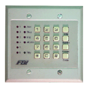
Table Of Contents (cont’d)
••••••••••••••••••••••••••••••••••••••••••••••••••
iv
Programming Questions - Installer Programming .........................................................................................9–2
Zone Programming..........................................................................................................................................9–19
Programming Questions - RF Programming............................................................................................10–1
Data Entry via LED Based Keypads...........................................................................................................11–1
General Information .......................................................................................................................................11–1
Entering Programming Mode via Keypad.....................................................................................................11–1
What You See on the LED Keypad ................................................................................................................11–1
Entering Data..................................................................................................................................................11–2
Summary of System Programming................................................................................................................11–4
Summary of Keypad Functions ...................................................................................................................12–1
User Functions ................................................................................................................................................12–1
Installer Modes................................................................................................................................................12–1
Central Station Reporting Formats.............................................................................................................A–1
Standard (3X1 or 4X1) .....................................................................................................................................A–1
Extended (3X1 Ext. or 4X1 Ext.).....................................................................................................................A–2
Partial Extended (3X1 Part. Ext. or 4X1 Part. Ext.) .....................................................................................A–2
3X2 or 4X2 ........................................................................................................................................................A–3
ADEMCO 4X2 Express.................................................................................................................................... A–3
ADEMCO Point ID...........................................................................................................................................A–4
OMNI-408A System Programming Worksheet ..........................................................................................B–1
RF MODE PROGRAMMING .......................................................................................................................... B–3
Warnings and Limitations..............................................................................................................................C–1
FCC Statement and Telephone Problems..................................................................................................D–1
Warranty.............................................................................................................................................................E–1
Summary of Connections ............................................................................................................................... F–1
Summary of Connections................................................................................................................................. F–1

v
Conventions Used in This Manual
••••••••••••••••••••••••••••••••••••••••••••••••••
Before you begin using this manual, it is important that you understand the meaning of the following symbols.
ULThese notes include specific information that must be followed if you are installing this system for
a UL Listed application.
These notes include information that you should be aware of before continuing with the
installation, and which, if not observed, could result in operational difficulties.
These notes warn of conditions that could seriously affect the operation of the system, or could
cause damage to the system. Please read each warning carefully. This symbol also denotes
warnings about physical harm to the user
.

vi
Feature Summary of Version 1
••••••••••••••••••••••••••••••••••••••••••••••••••
The following system feature are supplied in Version 1:
Exit Bypass – This feature allows any delay zone or interior that is violated at the end of exit
time to be bypassed for that armed period if the bit is set. This feature, if enabled, takes
precedence over exit error (question 26, location 4, bit 3).
Pager/Follow-Me – This feature allows the end user to access a user-programmable phone
number that can serve as a pager number or forwarding (site) number where the user can receive
digital messages from the OMNI-408A that are a result of programmable events occurring on the
system.
Bell Test from RF Keyfobs – This feature, if enabled, will activate bell test on arming/disarming
only from keyfobs. Arming/disarming from the keypad via user codes or quick function will not trip
the bell test (question 05, location 4, bit 2).
RF Board Detect – The panel senses if the ZR401 RF board is attached to the control panel. This
option is only viewable through the downloader.
Bell Test on Arming – If the "bell test chirp" is selected (question 08, location 1, bit 3) Bell Test
on Arm provides a single Bell chirp when arming and a double chip on disarming.
Strobe Trigger – Allows the trigger output to Pulse with the same timing as the Bell Test option
(chirp or non-chirp).
Limited Access to Programming – Prevents the installer from accessing questions 01 through
03 and 09 and 10 in keypad programming. This feature is set in the downloader only.
RF Programming Using Bypass Key – This feature, if enabled, allows access to RF
programming by pressing the [Bypass] key and the 2-digit RF question number. Otherwise the
method is to press [*] [#] and the 2-digit RF question number.
Recent Panic – If enabled in question 37, location 4, when the Panic is pressed on a keyfob
followed by an arm or disarm function within a 1-minute window, the panel sends a recent panic
code to the central station.
Exit Programming Central Station Report – This feature, if enabled, sends a code to the
central station when exiting keypad programming.

1–1
SECTION 1
Introduction
•••••••••••••••••••••••••••••••••••••••••••••••••
In This Section
♦About the OMNI-408A
•••••••••••••••••••••••••••••••••••••••••••••••••
About the OMNI-408A
The OMNI-408A Security System is a state-of-the-art, microprocessor-based
control/communicator. It is a hardwired/wireless system. You can program the system
through any of the compatible keypads; or the system can be uploaded and downloaded
remotely using the EZ-Mate PC Downloader Software. In addition, the software can perform
remote control actions (arming, disarming, bypassing, etc.). Programming options are stored
in nonvolatile reprogrammable EEPROM memory, which prevents information from being
lost in the event of a complete loss of power. Other features of the OMNI-408A include:
•8 Zones (4 hardwired or up to 8 wireless)
•On-board RF receiver compatible with ADEMCO 5800 Series Transmitters
•Up to 6 remote wireless keyfobs for quick one-button commands
•Capacity for up to 4 XK-108 keypads
•6 user codes with capability for Ambush code and an arm-only user
•Dedicated Bell Supervision input
•Temporal Bell option for fire sound
•4 selectable keypad emergency conditions
•Upload/download with remote commands with answering machine bypass
•Unattended and on-line downloading
•Default Lockout option to prevent hostile account takeovers
•Quick Arming, Quick Forced Arming, and Quick Bypass options
•Arm Faulted Quick Arming
•Quick Exit
•Indications on keypad for AC loss, low battery and communication failure
•Additional CS reporting formats (ADEMCO 4X2 Express and ADEMCO Point ID)
•Real-time, AC-based system clock
•Central station reporting for alarms, troubles, restores, bypasses, openings, closings,
ambush, panic, keypad fire, keypad medical, CS test, cancels, AC loss, low battery, RF
tamper, RF supervisory, RF low battery
•Exit Bypass
•Pager/Follow-Me
•Ability to be programmed as a local system (No CS reporting)
•4-wire smoke detectors with fire verification logic plus smoke power reset
•2 entry and 1 exit time delays
•Swinger Shutdown capability
•Exit Error Warning
•European Ring Detect
•98-Event Log History (viewable by PC downloading software only)

OMNI-408A Installation and Setup Guide
1–2
•End user chime ON/OFF toggle capability
•2 programmable trigger outputs for various functions (including armed/ready indication
and glassbreak detector reset)
•Input power: 16.5VAC 25VA; 12VDC, 4 - 7 AH
•Output power: 11.5 - 13.1VDC, 500mA
•Bell output power: 10 - 15.5VDC, 1A

2–1
SECTION 2
System Wiring and Hookup
••••••••••••••••••••••••••••••••••••••••••••••••••
In This Section
♦Wiring the OMNI-408A
♦System Stabilization Mode
♦Compatible ADEMCO 5800 Series Wireless Devices
♦Terminal Connections
♦Auxiliary Device Current Draw Worksheet
•••••••••••••••••••••••••••••••••••••••••••••••••
Wiring the OMNI-408A
Refer to the Summary of Connections diagram in Appendix F at the back of this guide for
visual information concerning the wiring and hookup of the OMNI-408A. The connections
shown meet Household Fire / Burglar Alarm System standards set by UL (UL985 and
UL1023).
System Stabilization Mode
Upon initial power-up of the system, all of the lights on the LED keypad(s) will go ON and
then go OFF for approximately 2 minutes, 10 seconds if the system was last armed. This
system stabilization mode occurs on a total power-up, on a system reset, or after completion
of system programming. If the total system power is lost, then upon power restoral the
system will return to the previous arming state. The 2-minute, 10-second interval is used to
allow motion detectors (in interior zones) to stabilize on power-up in order to prevent false
alarms. PUTTING A MOMENTARY JUMPER BETWEEN TERMINAL 15 AND 16 ON
POWER-UP CAN DISABLE THIS OPTION. IF DISABLED, THE POWER-UP RESET TIME
IS APPROXIMATELY 5 SECONDS. This is a normal condition.
Compatible ADEMCO 5800 Series Wireless Devices
•5802MN Single-Button Transmitter
•5802CP Belt Clip Panic Transmitter
•5804 4-Button Transmitter
•5806 Photoelectric Smoke Detector
•5807 Photoelectric Smoke Detector
•5808 Photoelectric Smoke Detector
•5816 Miniature Transmitter
•5817 3-Point Transmitter
•5818 Recessed Magnetic Contact Transmitter
•5849 Glassbreak Detector
•5890 Dual-Element PIR
NOTE: The OMNI-408A system is not compatible with the ADEMCO bi-directional devices.

OMNI-408A Installation and Setup Guide
2–2
Terminal Connections
TERMINALS FUNCTION DESCRIPTION
1 & 2 Transformer Connect the 16.5VAC 25VA transformer, utilizing #18awg
wire at a distance not to exceed 15 feet from the panel, to an
unswitched 120VAC outlet.
Do not use any other transformer, as this may result in
improper operation or damage to the unit.
The AC/LB keypad LED will remain on while AC power is
present. If an AC loss occurs, the AC/LB LED turns off
immediately. If AC power remains off for 15 minutes, the
system pulses the keypad buzzer (if enabled in Programming
question 07, location 4, bit 2) and transmits a power-loss
message to the central station, if programmed to do so. THE
KEYPAD BUZZER CAN BE SILENCED by entry of any valid
user code. When AC restores, the AC/LB LED lights
immediately, and a Restore code is reported, if programmed.
3Earth
Ground Connect this grounding lug to a cold-water pipe utilizing
#18awg wire at a distance of no greater than 15 ft. Use a
non-corrosive metal strap firmly secured to the pipe to which
the lead is electrically connected and secured. If the
premises' pipes terminate in PVC, this terminal must be
connected to a 6-foot grounding rod.
4(+) & 5(-) Bell Output The total output power available for sounding devices is 1A at
11.5 - 13.1VDC. These terminals deliver CONSTANT output
on BURGLARY, AUDIBLE PANIC, and BELL TEST. On a
FIRE condition, a PULSED or TEMPORAL output can be
generated. There are separate bell cutoff times
programmable for burglary and fire conditions within the
programming sequence. For UL Household Fire Warning
System installations, the speaker must be mounted indoors
for best audibility. Also, for UL installations, use only one
speaker.
NOTE: Before connecting sounding devices, consult their
specifications for proper current draw. Otherwise, the bell
fuse (F1) may be blown.
6Siren
Supervision
Input
The bell output may be supervised when a conventional bell
or a self-contained siren is connected. When connecting a
conventional bell or a self-contained siren to the bell output
terminals (4 and 5), the jumper JP3 must be placed across
pins 1 and 2. When connecting an external siren driver to the
bell output terminals, the supervision wire is connected to the
siren supervision terminal of the siren driver, and the jumper
JP3 must be placed across pins 3 and 4. A supervisory
condition generates a pulsing keypad sounder. Also, the
supervisory LED on the keypad pulses. Entering a valid user
code while the system is disarmed silences the sounder. The
LED continues to pulse until the supervision is fixed. If a bell,
self-contained siren, or external siren driver is not connected
to the bell output terminals, a 100-ohm resistor must be
placed across the siren supervision input to prevent a bell
supervision error. Bell supervision is reported to the CS if
enabled.

Section 2 - System Wiring and Hookup
2–3
TERMINALS FUNCTION DESCRIPTION
7(-) & 8(+)
(Trigger 1) Smoke
Detector
Power or
Trigger 1
Output
Smoke Detector Power: This system accepts 9.5 - 12VDC 4-
wire smoke detectors only. Approximately 50mA of current
are available at these terminals for powering all detectors and
an EOL relay FBII Model 620. For UL installations, see wiring
diagram for hookup.
These terminals adhere to the fire verification and reset logic.
You can reset the smoke detector power manually by
entering a valid user code after clearing alarm memory or by
using the asterisk [*] key.
Trigger 1 Output: These terminals which are commonly wired
to trigger 1, can be used for a trigger output. See
programming question 28, locations 1 and 2 for valid trigger
types.
5(-) & 8(+) Regulated
Power (11.5
- 13.1VDC):
The total regulated output power for motion detectors and
other external devices is 500mA at 11.8 - 12.5V for
residential applications, or 12.0 - 12.5V for commercial
applications, with less than 100 mVPP ripple. The total
regulated output capacity of the OMNI-408A includes the
power available from these terminals (8 and 5) as well as the
power used by the keypads and smoke detectors. Therefore,
to determine the total power available from these terminals,
subtract the power consumed by the keypads and smoke
detectors.
9(+) & 10(-)
11(+) & 10(-)
12(+) & 13(-)
14(+) & 13(-)
Zone
Information
(hardwired
zones)
Zone 1 (Requires 2.2K EOL resistor) [Default = Delay]
Zone 2 (Requires 2.2K EOL resistor) [Default = Interior]
Zone 3 (Requires 2.2K EOL resistor) [Default = Perimeter]
Zone 4* (Requires 2.2K EOL resistor) [Default = Perimeter]
Normally-closed devices may be wired in series; normally-
open devices may be wired in parallel. A 2.2k-ohm end-of-
line resistor must be installed on all zones. (Refer to the
wiring diagram.) The standard loop response time is 280 ms
on all zones. The factory default values for each zone are
listed in the table above; however, any zone can be
programmed for the following types: delay, perimeter, interior,
fire, 24-hr. alarm, or 24-hr. trouble. See further explanation of
the zone types in the
Section 9
:
System Programming
.
NOTE: Loop response is defined, as the minimum time
required for a fault to trip a zone.
*If Pool Zone option is enabled, see the “Pool Zone
Connections” description below for zone 4 usage.
RF Zone
Interface Zone
Information
(wireless
zones)
Zone 5 (Compatible RF Devices) [Default = Perimeter]
Zone 6 (Compatible RF Devices) [Default = Perimeter)
Zone 7 (Compatible RF Devices) (Default = Perimeter]
Zone 8 (Compatible RF Devices) [Default = Perimeter]
Wireless zones can be enabled in program question 26,
locations 1 and 2. All 8 zones can be wireless; or up to 4
zones can be hardwired and the remaining ones wireless.
Compatible ADEMCO 5800 Series wireless devices must be
used.

OMNI-408A Installation and Setup Guide
2–4
TERMINALS FUNCTION DESCRIPTION
15 (Black),
16 (Yellow),
17 (Green),
18 (Red)
Keypads Up to 4 keypads (XK-108) may be wired to these terminals.
The connections are as follows: 15 (Black) = negative, 16
(Yellow) = data in, 17 (Green) = data out, and 18 (Red) =
positive power. Each keypad draws approximately 30mA.
Maximum keypad length is 500 feet using 22-gauge wire.
NOTE: In some installations, it may be necessary to use
shielded wire to prevent radio frequency interference.
19 (Brown),
20 (Gray),
21 (Green),
22 (Red)
Telephone
Line Connect the model 368 cord as follows: 19 (Brown) = Home
Tip, 20 (Gray) = Home Ring, 21 (Green) = Telco Tip, and 22
(Red) = Telco Ring. Insert the plug into an USOCRJ31X Jack
(or a CA31A Jack for Canadian installations).
The FCC registration number is AE398E-69554 AL-E, and
the ringer equivalence is 0.0B. The system should not be
connected to party lines or coin-operated phones.
If this control panel will be used for uploading, downloading
or remote-command applications, the telephone line
connected to the control panel
must not
be shared with a fax
machine or modem. Furthermore, this device should not be
connected to a phone line that has Call Waiting, unless the
Call Waiting Interrupt numbers are programmed into the
panel dialing sequence.
BACKUP BATTERY:
The Red (+) and Black (-) flying leads must be connected to a 12VDC 4-7AH gell cell, to serve
as backup power in the event of AC loss.
A battery test occurs approximately every 4.5 minutes. Low-battery condition occurs at
nominal 11VDC. The keypad AC/LB LED and buzzer will pulse slowly when a low-battery
condition is detected. The system reports this condition to the central station if programmed
to do so. Battery restoral occurs within 4.5 minutes, at the NEXT battery test. The buzzer
may be silenced by entry of any valid user code.
POOL ZONE CONNECTIONS:
Zone 4 can be used for the Pool Zone option. To use Zone 4 for the Pool Zone option, all doors
with direct access to the pool shall be equipped with an alarm that produces an audible
warning when the door and its screen are opened. The alarm will sound continuously for a
minimum of 30 seconds immediately after the door is opened, and must be capable of being
heard throughout the house during normal household activities. The alarm automatically
resets under all operating conditions. The momentary switches provide temporary alarm
deactivation (15 seconds) so that the door can be opened without the alarm sounding.
When the Pool Zone option has been selected, Zone 4 operates as a standard delay zone when
the system is armed and the momentary switches start the entry time.
Figure 1 shows the wiring connections needed to use Zone 4 as a Pool Zone.

Section 2 - System Wiring and Hookup
2–5
Figure 1. Pool Zone Connections
Auxiliary Device Current Draw Worksheet
DEVICE CURRENT DRAW
FOR EACH NUMBER OF
UNITS TOTAL CURRENT FOR
EACH
XK-108 Keypad 30mA
PIR **
Smoke Detector **
Glassbreak Detector **
**
**
Total Current or all Devices = (500mA max.)
**If devices such as PIRs, smoke detectors, etc. are used, refer to the specifications for that
particular device's current draw. If the total current draw exceeds 500mA, then use an
additional power supply.
NFPA, UL, and the California State Fire Marshal require the backup battery to provide power for
24 hours. The maximum aux. power will vary by the ampere/hour rating of the battery used:
5AH = 95mA; 7AH = 180mA; 8AH = 210mA.
13
14
DOOR CONTACT
INSIDE WALL
MOMENTARY SWITCH* OUTSIDE MOMENTARY
SWITCH*
2.2 K EOL
RESISTOR
* SWITCHES MUST BE MOUNTED AT LEAST 54 INCHES ABOVE THE
DOOR THRESHOLD.

OMNI-408A Installation and Setup Guide
2–6

3–1
SECTION 3
PC Board Mounting
••••••••••••••••••••••••••••••••••••••••••••••••••
In This Section
♦Mounting the Control Board
♦Mounting the Receiver and Antennas
•••••••••••••••••••••••••••••••••••••••••••••••••
Mounting the Control Board
Before mounting the printed circuit board, be certain that the appropriate metal knockouts
have been removed. DO NOT ATTEMPT TO REMOVE THE KNOCKOUTS AFTER THE
CIRCUIT BOARD HAS BEEN INSTALLED.
NOTE: The front face (door) of the enclosure can be completely removed to gain unrestricted
access to the control panel during installation. To remove the door perform steps 1 and 2,
otherwise proceed to step 3:
1. Open the door to its fully extended position (approximately 90 degrees)
2. Lift the control panel door to remove it from the enclosure.
3. To mount the PC board, hang the three mounting clips on the raised cabinet tabs.
Observe proper clip orientation to avoid damage to the clip when mounting screws are
tightened and to avoid problems with insertion and removal of the PC board.
4. Insert the top of the circuit board into the slots at the top of the cabinet. Make sure that
the board rests in the slots as indicated in the figure below.
5. Swing the base of the board onto the mounting clips.
DETAILED SIDE VIEW
OF BOARD INSERTED
INTO SLOTS
DETAILED SIDE VIEW
OF CLIP AND BOARD
INSTALLED
B
A
DETAILED SIDE VIEW
OF CLIP INSTALLATION:
A. CABINET TAB
WITHOUT CLIP
B. CABINET TAB
WITH HANGING
CLIP
3rd CLIP
REQUIRED
PC Board
KNOCKOUT
Metal Cabinet
ZR-401 RF
RECEIVER
ANTENNAS
INSERT IN
RIGHT-HAND
TERMINALS
GROUND
TERMINALS
RCVR BOARD
CABINET
ANTENNA AND
GROUNDING LUG
INSTALLATION
ANTENNA
SCREW
GROUNDING LUG
Figure 2. Mounting the Control Board

OMNI-408A Installation and Setup Guide
3–2
6. Place the washer provided over the wire jumpers located within the middle of the PC
board. Secure the PC board to the middle-mounting clip of the enclosure through the
washer, using the screw provided.
7. Secure the remaining sides of the PC board to the enclosure, using the screws provided.
Mounting the Receiver and Antennas
1. Mount the receiver board on top of the control PC board as shown in the figure above.
2. Insert grounding lugs (supplied) into the left-hand terminals of the antenna blocks and
secure them to the cabinet with the screws provided.
3. Insert the receiver's antennas through the top of the cabinet into the blocks' right-hand
terminals. Tighten screws.

4–1
SECTION 4
Keypad Mounting
••••••••••••••••••••••••••••••••••••••••••••••••••
In This Section
♦Mounting the XK-108 Keypad
•••••••••••••••••••••••••••••••••••••••••••••••••
How to Mount the XK-108 Keypad
The XK-108 Keypad may be surface-mounted in any of the following three ways:
•Directly to a control panel enclosure if it has a keypad cutout on the front.
•Directly to a single- or double-gang electrical junction box.
•Directly to a wall or other surface.
Removing the Keypad Cover Assembly
Remove the keypad cover assembly from the rear mounting plate by inserting a small
screwdriver blade in the COVER PRY-OFF SLOTS at the lower edge of the keypad (see
Figure 3) and twist to pry off the cover assembly.
COVER
REAR PLATE BREAK-AWAY RIBS (4)
(FOR EXPOSED WIRING ENTRY.)
SLOT FOR COVER SECURING SCREW
(OPTIONAL)
COVER PRY-OFF SLOTS (2)
(TO REMOVE COVER, INSERT SMALL
SCREWDRIVER BLADE AND TWIST.)
DOOR
Figure 3. Bottom View of Keypad
Mounting the Rear Plate
Mount the rear plate as shown in Figure 4. Note that the plate is correctly oriented when its
part number, molded into the plastic, is upright.
AAB
AAB
N6054
HOLDING HOOKS
(
2
)
(FOR HOLDING COVERS UPPER EDGE) HOLES “A”
(
4
)
(FOR MOUNTING TO
CONTROL PANEL’S
ENCLOSURE OR
TWO GANG
ELECTRICAL BOX)
HOLES “B”
(
2
)
(FOR MOUNTING TO
SINGLE GANG
ELECTRICAL BOX)
HOLES “A” OR “B”
(CAN BE USED
FOR WALL MOUNTING)
SNAP HOOKS
(
2
)
(FOR HOLDING COVER’S
LOWER EDGE)
BREAK-AWAY RIBS
(
4
)
(FOR EXPOSED WIRING ENTRY.)
POST FOR COVER
SECURING SCREW (OPTIONAL)
WIRING
OPENING
(FOR
CONCEALED
WIRING)
Figure 4. Rear Mounting Plate

OMNI-408A Installation and Setup Guide
4–2
Mounting Directly to Control Panel Enclosure
If the control panel enclosure has a keypad cutout on the front face, remove the cutout and
mount the plate to the enclosure's face via HOLES “A” (see Figure 4) with the four screws
and nuts provided.
Mounting Directly to an Electrical Junction Box
The plate can be mounted directly to a single- or double-gang electrical junction box. Use the
screw holes provided and HOLES “B” for a single-gang box or HOLES “A” for a double-gang
box.
Mounting Directly to a Wall or Other Surface
Provide a wiring hole in the mounting surface. Position the plate's WIRING OPENING over
the hole and mounting plate, using HOLES “A” and/or “B” in conjunction with appropriate
mounting hardware (not provided) for the type of surface.
1. Complete the keypad wiring as required for the control with which the keypad is to be
used.
2. Replace the keypad cover assembly on the rear plate. Starting at the upper edge of the
plate, engage the plate's two HOLDING HOOKS (see Figure 4) into the recesses provided
for them inside the upper edge of the cover assembly. Snap the lower edge of the cover
assembly and the lower edge of the cover onto the two SNAP HOOKS at the lower edge of
the plate.
NOTE: If desired, cover and plate can be further secured together by inserting a screw
(provided) into the SLOT at the keypad's lower edge.
NOTE: When surface mounting the keypad and using screws with heads larger than the
screws provided with the unit, place electrical tape over the screws to prevent them from
interfering with the keypad operation.

5–1
SECTION 5
The XK-108 Keypad
••••••••••••••••••••••••••••••••••••••••••••••••••
In This Section
♦XK-108 Keypad
♦ Keypad Sounder
•••••••••••••••••••••••••••••••••••••••••••••••••
XK-108 Keypad
ARM
AC/LB
READY
1
2
3
4
5
6
7
8
Stay
Instant
COVER
OPEN
Stay Instant
Bypass Code
*
0#
789
456
123
P
A
F
2
3
6
1
3
4
7
9
10
8
11
RF LB
Superv
12
13
Figure 6. XK-108 Keypad
Table 1. XK-108 Keypad Controls and Indicators
INDEX
NO. CONTROL/
INDICATOR DESCRIPTION
1 Zone Status
LEDS These LEDs display the current zone status, including alarms,
bypasses, troubles, and faults. Each condition will cause these LEDs to
operate differently, as follows:
Alarms — Fast Blink (approx. 150mS on - 150mS off).
Troubles — Slow Pulse (approx. 600mS on - 600mS off).
Bypasses — Wink (100mS on - 900mS off). Zone bypasses are
displayed as a very slow wink of the zone LED light.
Faulted Zones — Solid on. Faulted zones are the lowest-priority
indication. Faulted burglary zones are displayed with the LED solidly on
while the system is disarmed.
Normal — Off.

OMNI-408A Installation and Setup Guide
5–2
INDEX
NO. CONTROL/
INDICATOR DESCRIPTION
2ARM/DISARM
LED This LED indicates whether the system is currently armed (on) or
disarmed (off). This LED will also blink fast to show that alarms have
occurred; or blink slowly upon failure to communicate with the central
station.
3 Stay LED This LED displays whether the system has been armed in the Stay
mode or the Stay/Instant mode. If the Instant LED is on and the Stay
LED is on, then the system is in the Stay/Instant mode. If the Instant
LED is off and the Stay LED is on, then the system is in the Stay mode
only. Stay/Instant is enabled in programming question 08, location 3. In
either mode, the Stay LED indicates the following:
On — All zones enabled for Stay are bypassed.
Off — Zones are active-armed.
4 Instant LED This LED displays whether the system has been armed in the
Stay/Instant mode, Instant mode, or indicates if the account is not being
monitored by the CS. Stay/Instant means that the system is currently
armed, all delay zones are Instant and all interior zones are bypassed.
Instant means that the system is currently armed, all delay zones are
Instant and no zones are bypassed.
NOTE: See programming question 08, location 3.
On — Delay zones are currently instant.
Off — Delay zones are normal.
Pulse — Central station is not monitoring the account.
5 AC/LB LED This indicator light displays the current power status of the panel as
follows:
On — AC is present.
Off — No AC, running on battery backup.
Slow Blink — Low-battery condition detected.
6 READY LED This LED displays whether the system is ready for arming. The READY
LED is common to all burglary zones with the following indications:
On — System ready to be armed.
Off — System not ready to be armed.
Slow Blink — Indicates Installer Programming mode.
Fast Blink — Alarm Memory mode.
7 [Stay] Key The [Stay] key enables arming the system, excluding zones
programmed with the Stay option. This provides exterior protection of
the location while allowing full access throughout the interior. The [Stay]
key is also used to exit Installer Programming mode.
8 [Bypass] Key The [Bypass] key is used to temporarily exclude protection of a specific
zone.
9 [Instant] Key The [Instant] key enables arming the system, eliminating the entry
delays. If enabled with the [Stay] key, it enables arming the system in
the Stay/Instant mode.
NOTE: Instant modes are enabled in question 08, location 3.
10 [Code] Key The [Code] key is used to enter the Installer Programming mode and for
entry of user codes.
Table of contents
Other FBII Security System manuals