Fbt Ventis 115A User manual
I
UK
S P E A K E R S Y S T E M S
User's Manual
Manuale d'uso

INDICE CONTENTS
AVVERTENZE / WARNINGS
CARATTERISTICHE / FEATURES
ALIMENTAZIONE / POWER SUPPLY
CONNETTORI / CONNECTORS
INSTALLAZIONE / INSTALLATION
ACCESSORI / ACCESSORIES
MODALITÀ DI INSTALLAZIONE / INSTALLATION MODES
DIMENSIONI / DIMENSIONS
TROMBA RUOTABILE / ROTATABLE HORN
CONTROLLI E FUNZIONI / CONTROLS AND FUNCTIONS
DSP
Descrizione del menu / Menu description
Controllo dei parametri di sistema / System parameters control
Descrizione delle voci del menu principale / Description of the main menu items
ESEMPI DI CONFIGURAZIONI / CONFIGURATION EXAMPLES
CARATTERISTICHE TECNICHE / TECHNICAL SPECIFICATIONS
1
2-3-4-5-6
7
7
8
9
10 - 11
12
13
14
15
15
16
17-18-19-20
21-22-23
24-25

IMPORTANTI ISTRUZIONI DI SICUREZZA IMPORTANT SAFETY INSTRUCTIONS
AVVERTENZE WARNINGS
1
PUSH FOR MENU
CARATTERISTICHE FEATURES
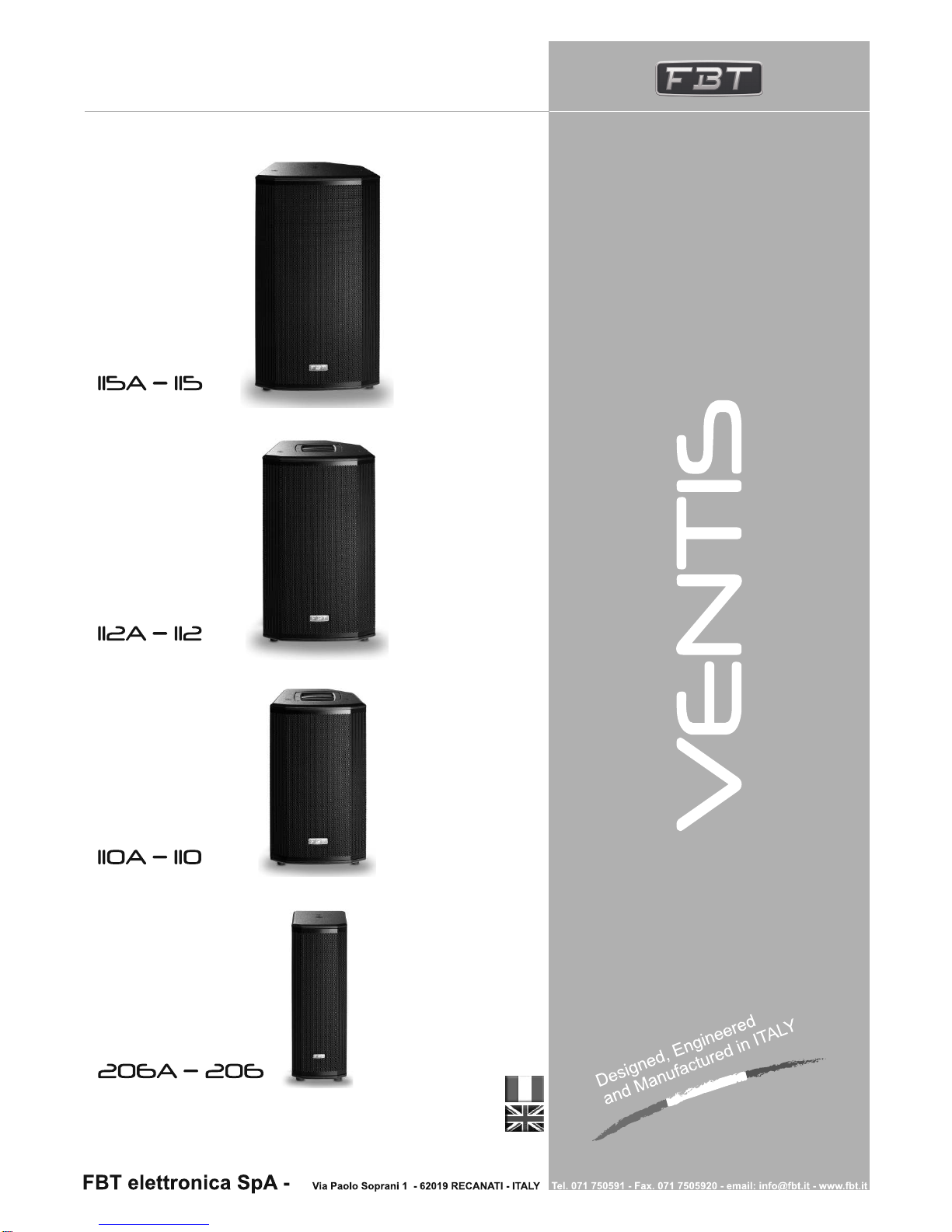
La gamma VENTIS della FBT comprende 4 diffusori versatili per
uso portatile o per installazioni fisse. Disponibili sia in versione bi-
amplificata o passiva, ciascuno dei modelli è stato progettato per
soddisfare i più elevati standard in termini di prestazioni ed estetica.
Il modello VENTIS 206 può essere impiegato come "sound
reinforcement", come sistema "under-balcony", come principale
fonte del parlato per la sua alta intelligibilità o semplicemente come
il compagno ideale di un subwoofer. Tutti i modelli VENTIS sono
dotati di un modulo di amplificazione switching progettato in Italia.
L'amplificatore di potenza integrato in Classe D per le basse
frequenze eroga 700W RMS ; per le alte frequenze la sezione
amplificatrice è in Classe H-AB ( 200W RMS ). All'interno un
processore di segnale digitale (DSP), dotato di una interfaccia
grafica intuitiva; situato sul pannello posteriore, il display DSP
visualizza tutte le scelte dal menu editabili tramite una sola
manopola con funzionalità "push-to-select".
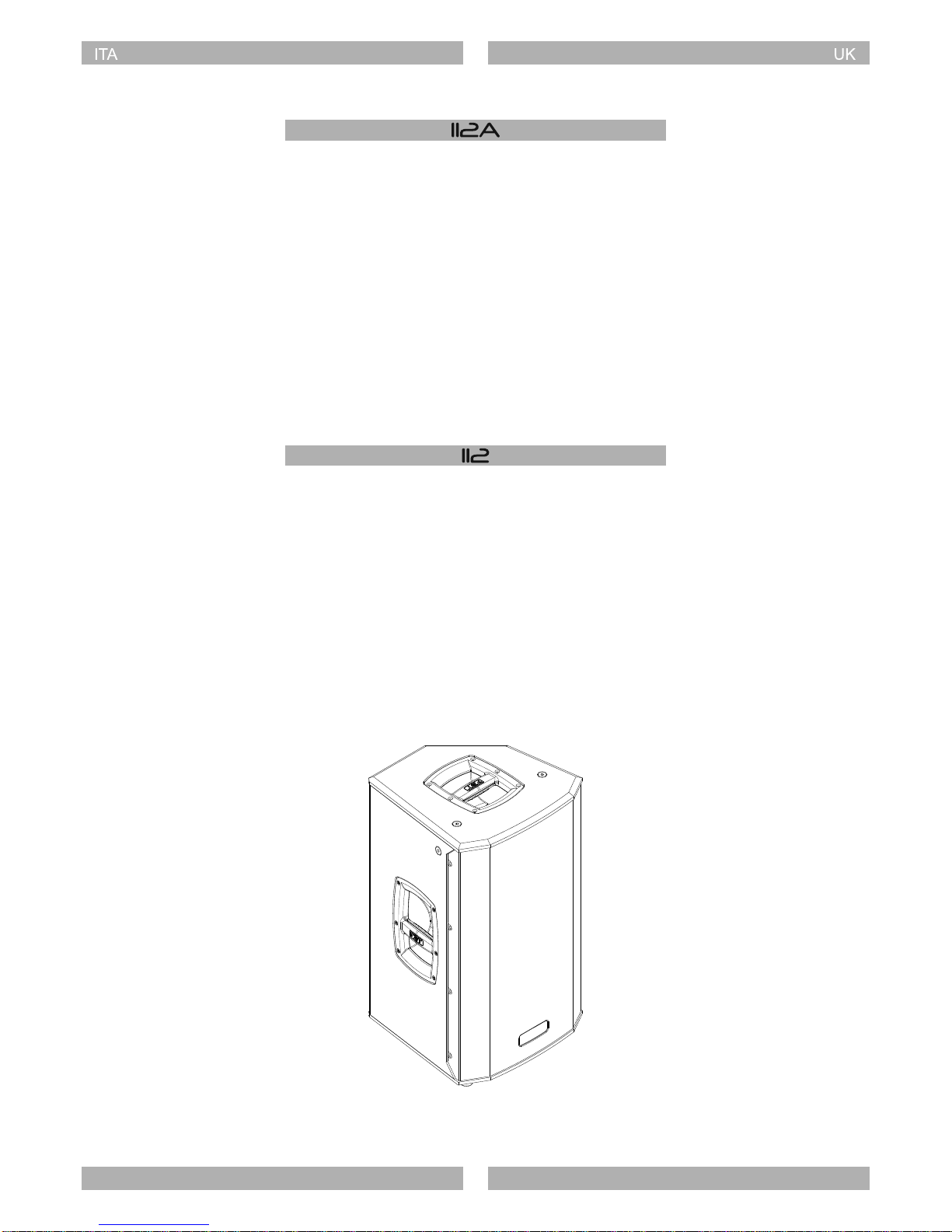
Costruiti in multistrato di betulla, dispongono di un profilo inclinato a
45° per il posizionamento su palco come monitor, di diversi punti di
ancoraggio e la possibilità di essere installati a parete tramite staffa
ad "U".
Versione attiva
Active version
Versione passiva
Passive version
2
The VENTIS range by FBT comprises 4 versatile loudspeakers for
either portable use or fixed installation. Available in bi-amplified or
passive versions, each model was designed to meet the highest
standards in both performance and aesthetic appeal. VENTIS 206
can be used as sound reinforcement, as an under-balcony system,
as a main source for speech for its high intelligibility or simply as the
full-range companion of a subwoofer. All VENTIS models are
equipped with a switching amplification module designed in Italy.
The Class D integrated power amplifier for low frequencies supplies
700W RMS. For high frequencies, the amplifier section is Class H-
AB (200W RMS). A digital signal processor (DSP) is fitted inside
and equipped with an intuitive graphical interface; situated on the
rear panel, the DSP display shows all the menu choices, which can
be edited via a single knob with push-to-select features. Made from
birch plywood, they have a profile tilted at 45° for positioning on
stage as a monitor, with various anchoring points and the option of
being wall-mounted by means of a U-bracket.
CARATTERISTICHE FEATURES
PROCESSED ACTIVE SPEAKER
- 700W + 200W RMS
- 2 x woofer custom 165mm con bobina da 38mm
- Driver B&C con bocca da 25mm e bobina da 36mm
- Risposta in frequenza da 70Hz a 20kHz
- Tromba 70°H x 50°V ruotabile
- Staffa per installazione a muro (opzionale)
- Supporto per stativo da 35mm
- Maniglia posteriore integrata
- Cabinet in multistrato di betulla da 12mm
PROCESSED ACTIVE SPEAKER
- 2 x 6.5" LF woofers with 1.5" voice coil
- 1" exit throat B&C HF compression driver with 1.4" voice coil
- Frequency response from 70Hz to 20kHz
- 70°H x 50°V rotatable horn
- Wall bracket mount thread(optional)
- 1.38" top-heat
- One integrated handle
- 0.47" birch plywood enclosure
- 700W + 200W RMS
PASSIVE REINFORCEMENT SPEAKER
- 400W / 8 Ohm
- Crossover passivo interno con protezione soft trip su WF e TW
- Connettori Speakon NL-4 IN & LINK out
- Risposta in frequenza da 75Hz a 20kHz
PASSIVE REINFORCEMENT SPEAKER
- 400W / 8 Ohm
- Built-in passive crossover with soft-trip protection for the WF & TW
- Speakon NL-4 IN & LINK out connectors
- Frequency response from 75Hz to 20kHz
3
CARATTERISTICHE FEATURES
CARATTERISTICHE FEATURES
PROCESSED ACTIVE SPEAKER
- 700W + 200W RMS
- Woofer custom 250mm con bobina da 50mm
- Driver B&C con bocca da 25mm e bobina da 36mm
- Risposta in frequenza da 58Hz a 20kHz
- Tromba 80°H x 50°V ruotabile
- Staffa per installazione a muro (opzionale)
- Supporto per stativo da 35mm
- Maniglia in alluminio
- Cabinet in multistrato di betulla da 15mm
PROCESSED ACTIVE SPEAKER
- 10" LF woofer with 2" voice coil
- 1" exit throat B&C HF compression driver with 1.4" voice coil
- Frequency response from 58Hz to 20kHz
- 80°H x 50°V rotatable horn
- Wall bracket mount thread(optional)
- 1.38" top-heat
- Aluminium handle
- 0.59" birch plywood enclosure
- 700W + 200W RMS
PASSIVE REINFORCEMENT SPEAKER
- 300W / 8 Ohm
- Crossover passivo interno con protezione soft trip su WF e TW
- Connettori Speakon NL-4 IN & LINK out
- Risposta in frequenza da 60Hz a 18kHz
PASSIVE REINFORCEMENT SPEAKER
- 300W / 8 Ohm
- Built-in passive crossover with soft-trip protection for the WF & TW
- Speakon NL-4 IN & LINK out connectors
- Frequency response from 60Hz to 18kHz
4
CARATTERISTICHE FEATURES
PROCESSED ACTIVE SPEAKER
- 700W + 200W RMS
- Woofer custom 320mm con bobina da 64mm
- Driver B&C con bocca da 25mm e bobina da 36mm
- Risposta in frequenza da 48Hz a 20kHz
- Tromba 80°H x 50°V ruotabile
- Staffa per installazione a muro (opzionale)
- Supporto per stativo da 35mm
- Due maniglie in alluminio
- Cabinet in multistrato di betulla da 15mm
PROCESSED ACTIVE SPEAKER
- 12" LF woofer with 2.5" voice coil
- 1" exit throat B&C HF compression driver with 1.4" voice coil
- Frequency response from 48Hz to 20kHz
- 80°H x 50°V rotatable horn
- Wall bracket mount thread(optional)
- 1.38" top-heat
- Two aluminium handles
- 0.59" birch plywood enclosure
- 700W + 200W RMS
PASSIVE REINFORCEMENT SPEAKER
- 400W / 8 Ohm
- Crossover passivo interno con protezione soft trip su WF e TW
- Connettori Speakon NL-4 IN & LINK out
- Risposta in frequenza da 55Hz a 18kHz
PASSIVE REINFORCEMENT SPEAKER
- 400W / 8 Ohm
- Built-in passive crossover with soft-trip protection for the WF & TW
- Speakon NL-4 IN & LINK out connectors
- Frequency response from 55Hz to 18kHz
5

CARATTERISTICHE FEATURES
PROCESSED ACTIVE SPEAKER
- 700W + 200W RMS
- Woofer custom 380mm con bobina da 64mm
- Driver B&C con bocca da 25mm e bobina da 44mm
- Risposta in frequenza da 42Hz a 20kHz
- Tromba 80°H x 50°V ruotabile
- Staffa per installazione a muro (opzionale)
- Supporto per stativo da 35mm
- Due maniglie in alluminio
- Cabinet in multistrato di betulla da 15mm
PROCESSED ACTIVE SPEAKER
- 15" LF woofer with 2.5" voice coil
- 1" exit throat B&C HF compression driver with 1.7" voice coil
- Frequency response from 42Hz to 20kHz
- 80°H x 50°V rotatable horn
- Wall bracket mount thread(optional)
- 1.38" top-heat
- Two aluminium handles
- 0.59" birch plywood enclosure
- 700W + 200W RMS
PASSIVE REINFORCEMENT SPEAKER
- 500W / 8 Ohm
- Crossover passivo interno con protezione soft trip su WF e TW
- Connettori Speakon NL-4 IN & LINK out
- Risposta in frequenza da 50Hz a 18kHz
PASSIVE REINFORCEMENT SPEAKER
- 500W / 8 Ohm
- Built-in passive crossover with soft-trip protection for the WF & TW
- Speakon NL-4 IN & LINK out connectors
- Frequency response from 50Hz to 18kHz
6
ALIMENTAZIONE POWER SUPPLY
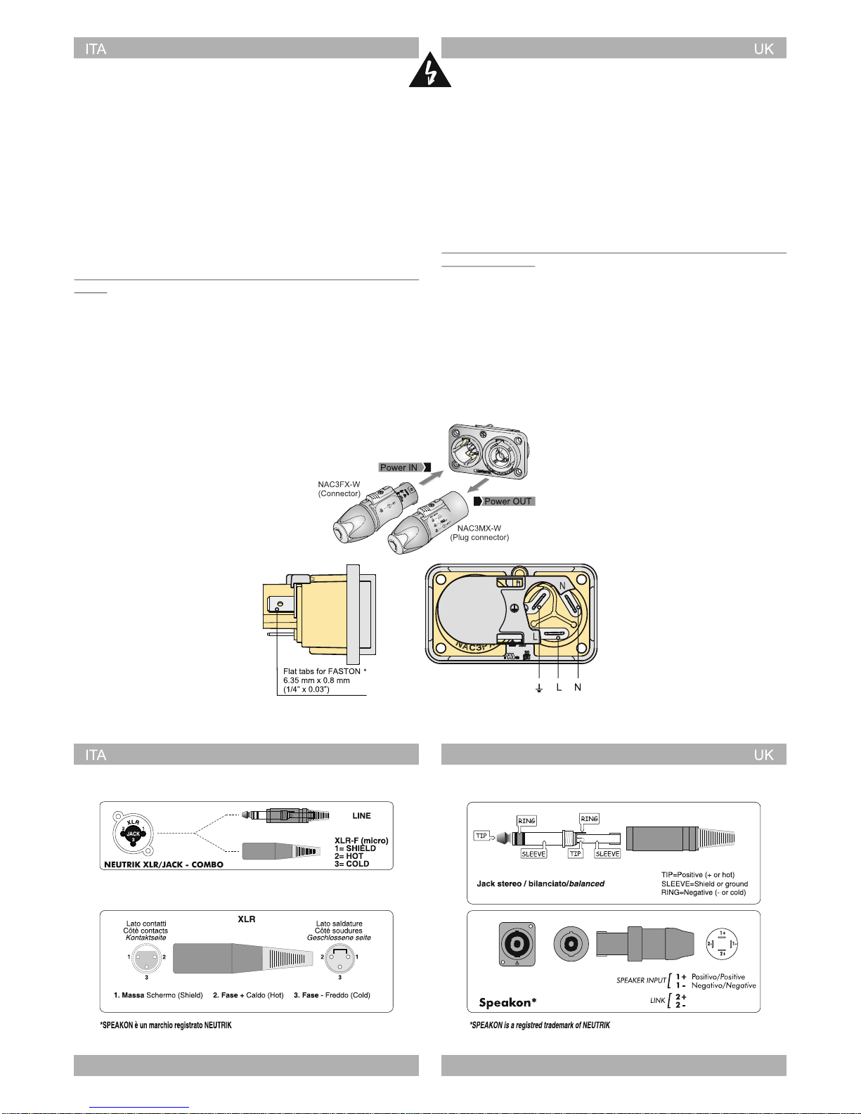
ALIMENTAZIONE 230V:
Per l'alimentazione elettrica il modello VENTIS è fornito di una
presa Neutrik PowerCon THRU 1 con ingresso ed uscita.
ATTENZIONE: non sostituire la spina in dotazione del cavo di
alimentazione con un'altra spina, in quanto il cavo di alimentazione
è in grado di supportare una corrente massima di 16A
ALIMENTAZIONE 120V:
Se la richiesta complessiva di corrente è inferiore a 15A utilizzare il
cavo di alimentazione in dotazione. Se la richiesta complessiva di
corrente è superiore a 15A ed inferiore a 20A utilizzare un cavo di
alimentazione AWG12 SJT VW1 con una spina di corrente
nominale superiore o uguale a 30A.
IL CAVO E LA SPINA DEVONO ESSERE CERTIFICATI "UL" O
"CSA"
POWER SUPPLY 230V:
For power supply VENTIS model features a Neutrik PowerCon
THRU 1 with input and output.
CAUTION: never replace the plug of the power cord supplied since
the power cord can only support a maximum current of 16A.
POWER SUPPLY 120V:
If the total current demand does not exceed 15A use the power
cable supplied. If the total current demand is between 15A and 20A
user the power cable
THE CABLE AND THE PLUG MUST HOLD THE "UL" OR "CSA"
CERTIFICATION.
AWG12 SJT VW1 with plug rated current
equal or greater than 30A.
The "PowerCon True 1" system is certified as connector with
breaking capacity according IEC 60320, VDE 0625. It is intended
for use as appliance couplers and interconnection couplers. It
serves to supply power to an appliance and from an appliance to
another equipment. To be installed by qualified person only.
Il sistema "PowerCon True 1" è certificato come connettore con
capacità di interruzione in conformità alla norma IEC 60320, VDE
0625. È adatto per collegamento di dispositivi e interconnessioni.
Serve ad alimentare un dispositivo, oppure a fornire alimentazione
da un dispositivo ad un'altra apparecchiatura. Dovrà essere
installato esclusivamente da personale qualificato.
7
CONNETTORI CONNECTORS

INSTALLAZIONE INSTALLATION
VENTIS
VENTIS
VENTIS
VENTIS
VENTIS
VENTIS
VENTIS VENTIS
8
ACCESSORI ACCESSORIES
VENTIS VENTIS
VN-U206
249mm
9.80"
22.20" / 564mm
232mm
9.13"
232mm
9.13"
70mm
2.75"
VN-U110
253mm
9.96"
25.15" / 639mm
269.5mm
10.61"
269.5mm
10.61"
70mm
2.75"
VN-U112
283mm
11.14"
28.97" / 736mm
318mm
12.51"
318mm
12.51"
70mm
2.75"
VN-U115
9

MODALITÀ DI INSTALLAZIONE INSTALLATION MODES
I diffusori della serie VENTIS possono essere installati nei seguenti
modi:
- Sospensione mediante staffa a muro
- Installazione su supporto stativo
- Sospensione mediante cavi
- Semplice posizionamento a stack con subwoofer a terra e satellite
corrispondente appoggiato su di esso
VENTIS speakers can be installed as follow:
- Suspension by wall bracket
- Installation on tripod stand
- Suspension via cables
- Simple stack installation with the subwoofer on the ground
M10M10
M6
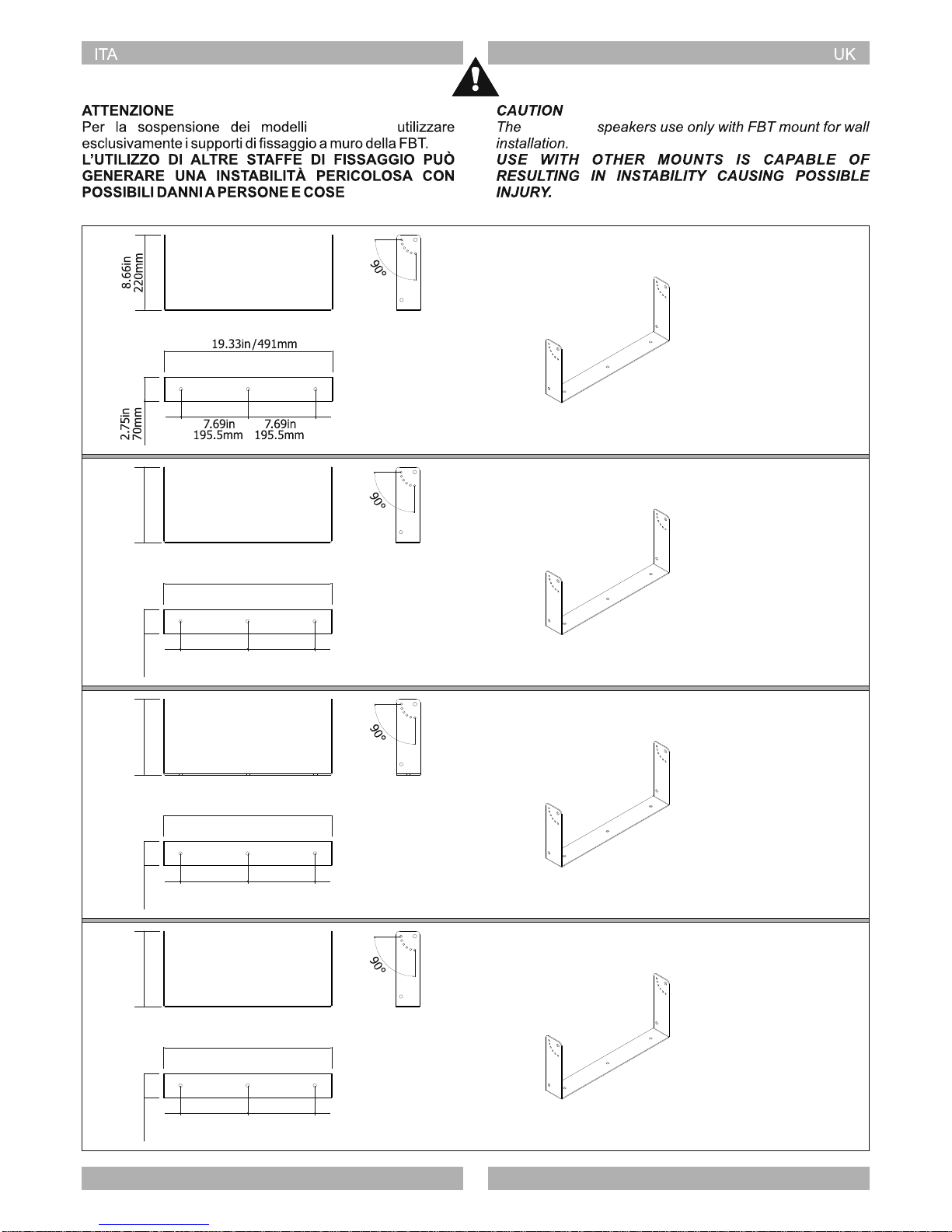
- Selezionare con cura l'area dove installare i diffusori e assicurarsi
che la struttura sia adeguata a supportare il peso del sistema
- Togliere i piedini in gomma di appoggio del diffusore
- Fissare la staffa al muro utilizzando appropriate viti su tutti i fori di
fissaggio della stessa
- Posizionare il diffusore tra i due bracci della staffa e fissarlo
utilizzando i due inserti filettati M10
- Orientare il diffusore nella posizione desiderata e bloccarlo tramite
il perno M6
SOSPENSIONE MEDIANTE STAFFA A MURO SUSPENSION BY WALL BRACKET
- Carefully choose speakers place of installation and make sure that
the structure can bear box weight
- Remove speaker's feet
- Secure the bracket to the wall by using screws in all its fixing holes
- Place the speaker between bracket arms and secure it through
two M10 threaded inserts
- Point the speaker as desired and lock it through the M6 pin
10
Con questo accorgimento si ha il vantaggio di avere le sorgenti
medio-alte più allineate con la posizione dell'orecchio
dell'ascoltatore.
- Accertarsi che lo stativo supporti il peso del diffusore
- Posizionare lo stativo su una superficie piana e non
sdrucciolevole.
- Per rendere più stabile lo stativo allargare al massimo la sua base.
Such installation will allow medium-high frequency sources to the
better aligned to listener's ear.
- Make sure that the stand can bear speaker's weight
- Place the stand on a flat and antislip surface
- Widen stand base as much as possible to increase its stability.
INSTALLAZIONE SU SUPPORTO STATIVO INSTALLATION ON TRIPOD STAND
N.B. Per il fissaggio della staffa
ad "U" in tutti i modelli VENTIS è
necessario rimuovere la flangia
per lo stativo ed inserire un
adattatore predisposto.
Solo per i modelli 112A e 110A ,
oltre all'adattatore per stativo è
ne ce ss ari o r imu ov er e la
maniglia ed inserire al suo posto
una flangia adatta allo scopo.
La staffa ad "U", l'adattatore e la
flangia vengono forniti assieme.
N.B. To fix the U-bracket on all
VENTIS models, you must
remove the flange for the stand
and insert a special adaptor. For
models 112A and 110A only,
besides the adaptor for the
stand, you must also remove the
handle and insert a suitable
flange instead of it. The U-
bracket, the adaptor and the
flange are supplied together.
MODALITÀ DI INSTALLAZIONE INSTALLATION MODES
11
Diffusori che devono essere trasportabili, riconfigurati su base
regolare o per realizzare impianti multipurpose, possono essere,
per comodità, essere impilati a terra.
- Verificare sempre la superficie di appoggio sulla quale va
collocato il sistema
- Ispezionate sempre la parte sottostante di qualsiasi struttura
temporanea per accertarvi che sia sufficientemente stabile e
robusta.
POSIZIONAMENTO A STACK
SOSPENSIONE MEDIANTE CAVI SUSPENSION VIA CABLES
STACK INSTALLATION
Speakers that must be transported, reconfigured on a regular basis
or to create multipurpose systems can be stacked on the ground for
convenience.
- Always check the support surface where the system is placed
- Always inspect the underlying part of any provisional structure to
make sure it is stable and sturdy enough.
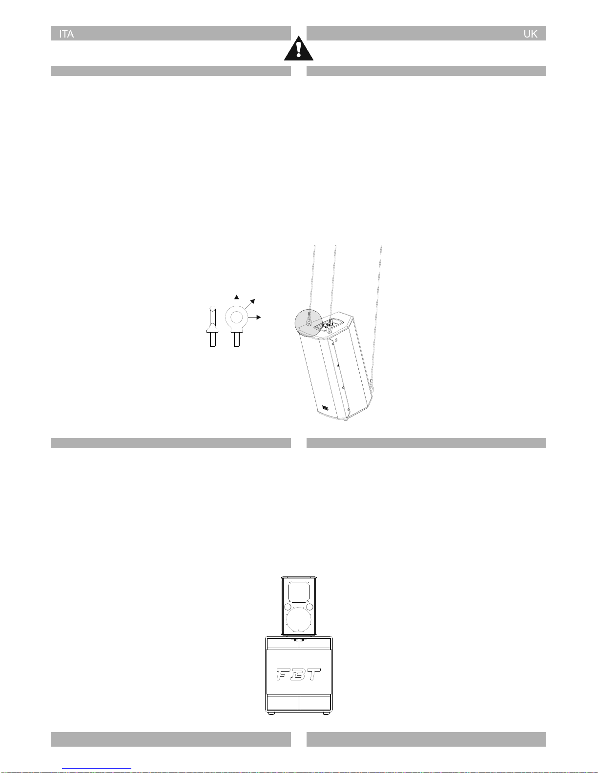
Per sospendere un solo diffusore devono essere utilizzati almeno
tre punti, sia per motivi di sicurezza, sia per garantire che la sua
struttura possa essere orientata correttamente. I due cavi frontali
costituiscono il sostegno principale, mentre il punto di supporto
posteriore consente al diffusore di essere inclinato o orientato.
Accertatevi che sia sufficiente la possibilità di regolazione prevista
dal sistema di aggancio per consentire l'angolazione in tutte le
direzioni richieste (collocazione, panoramica, inclinazione,
bloccaggio o spostamento).
Prima di sospendere il diffusore siate sicuri di aver compreso come
utilizzare correttamente i golfari di aggancio. Tenete presente che la
resistenza di un golfare differisce secondo l'angolo che forma con il
cavo di acciaio collegato ad esso e secondo l'angolo di
sospensione del diffusore.
For safety reasons and to make sure that the structure can be
oriented correctly, at least three points must be used to hang one
loudspeaker. The two front cables form part of the main support,
whereas the rear support enables the loudspeaker to be tilted and
oriented. Make sure that it is possible to make all the adjustments
provided by the coupling system to angle it in all directions
requested (location, panoramic, tilting, locking or displacement).
Before hanging the loudspeaker, make sure you have understood
how to use the coupling eyebolts correctly. Keep in mind that the
resistance of an eyebolt differs according to the angle that it forms
with the steel cable connected to it and according to the suspension
angle of the speaker.
0° 45°
90°
Golfare
Eye bolt
Q u an d o u s a t e i g o l f a r i
accertatevi che l'angolo di
sospensione sia compreso tra 0
e 45 gradi.
When using the eye bolts make
sure that the suspension angle is
within the range of 0 to 45
degrees.

DIMENSIONI DIMENSIONS
21.45" / 545mm
10.23" / 260mm
7.48" / 190mm
Front view Left view Rear view
Bottom view
Front view Left view Rear view
Bottom view
12.95" / 329mm 12.79" / 325mm
22.04" / 560mm
45°
15.74" / 400mm
13.70" / 348mm
Front view Left view Rear view
Bottom view 45°
18.58" / 472mm
15.70" / 399mm
14.96" / 380mm15.25" / 387.5mm
25.59" / 650mm
Front view Left view Rear view
Bottom view
45°
20.57" / 522.5mm
17.51" / 445mm
29.52" / 750mm
16.53" / 420mm16.83" / 427.5mm
12

TROMBA RUOTABILE ROTATABLE HORN
I diffusori della serie VENTIS sono forniti di tromba ruotabile per
adattare la dispersione del diffusore all'area di ascolto e alla
tipologia di installazione (orizzontale o verticale). I diffusori
vengono forniti dalla FBT sempre con la tromba orientata a 80° in
senso orizzontale per i modelli 110, 112 ,114 ; a 70° in senso
orizzontale per il modello 206.
80°
50°
70°
50°
ANGOLO DI COPERTURA TROMBA
HORN COVERAGE ANGLE
80°
50°
Utilizzo a monitor con tromba ruotata
Floor uses (monitor) with rotating horn
80°
50°
70°
50°
70°
50°
13
VENTIS speakers are equipped with a rotatable horn to adjust
dispersion of the speaker to the listening area and the type of
installation (horizontal or vertical). Speakers are always provided
by FBT with the horn oriented at 80° in a horizontal direction for
models 110, 112 ,114, and 70° in a horizontal direction for model
206.

CONTROLLI E FUNZIONI CONTROLS AND FUNCTIONS
PUSH FOR MENU
Versione attiva
Active version
Versione passiva
Passive version
12
34
5
6
7
8
9
9
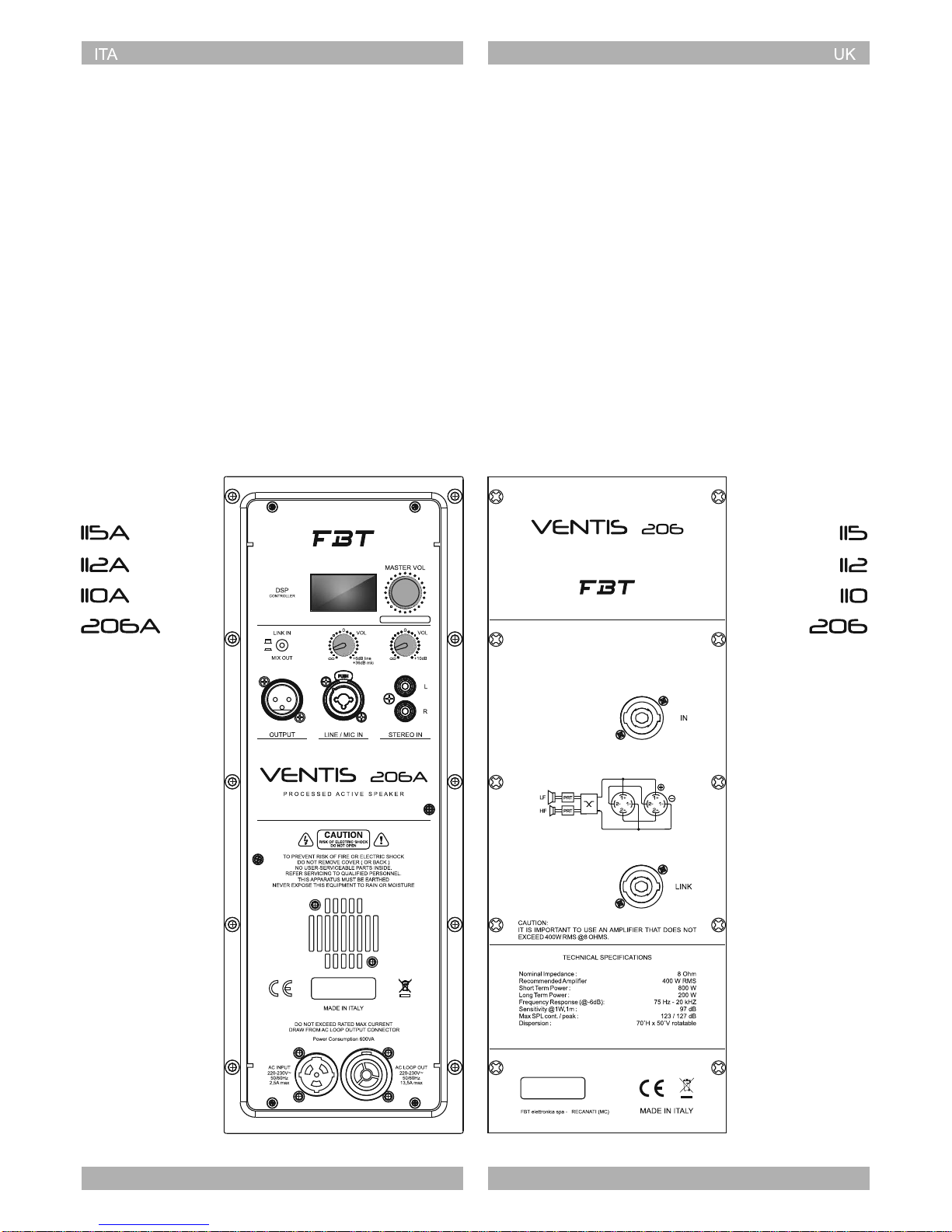
1. Visualizzazione menu e impostazioni del DSP.
2. Volume digitale generale per il controllo del livello dei segnali
miscelati. Premere per entrare nel menu del DSP e ruotare la
manopola per la scelta e la selezione dei parametri.
3. Selettore per la modalità del segnale di uscita tra il "link" fisico
dell'ingresso XLR o la miscelazione dei due canali di ingresso
(post-volume).
4. Volume dell'ingresso stereo.
5. Volume dell'ingresso linea / microfono .
6. Presa XLR per l'invio del segnale verso un'altro diffusore.
7. Ingresso combo bilanciato per il collegamento di sorgenti linea o
microfoniche (la selezione avviene tramite impostazioni nel
menu).
8. Ingresso RCA per il collegamento di sorgenti esterne come ad
esempio MP3 player
9. Prese Speakon collegate in parallelo; utilizzare una presa per il
collegamento del diffusore all'uscita di un amplificatore di
potenza, l'altra per collegare un secondo diffusore.
1. Menu display and DSP settings
2. General digital volume to control the level of mixed signals. Press
to access the DSP menu and turn the knob to select parameters.
3. Output signal mode selector between the physical link of input
XLR or a mixture of the two input channels (post-volume).
4. Stereo input volume.
5. Line/microphone input volume.
6. XLR outlet to send the signal to another speaker.
7. Combo balanced input to connect the line or microphone sources
(selection is made from the menu settings).
8. RCA input to connect external sources, for example an MP3
player
9. Speakon outlets connected in parallel. Use one outlet to connect
the speaker to the output of a power amplifier, and the other one
to connect a second speaker.
14
DSP DSP
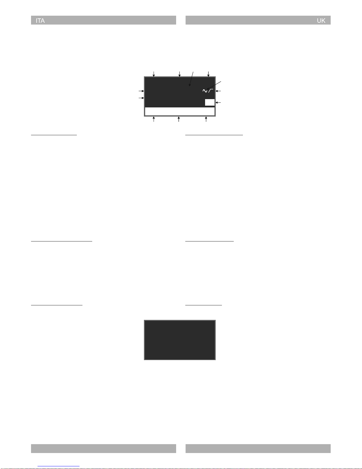
1. PRESET - Impostazioni del preset
2. EQUALIZZAZIONE - Di default tutti i guadagni dei filtri sono
impostati a zero; l'indicazione EQ sta a significare, invece, che i
valori dell'equalizzazione sono stati impostati.
3. VOLUME - Livello generale del sistema; può variare da 0dB a
MUTE a passi di 1dB.
4. POSIZIONAMENTO - Impostazioni della "location".
5. SENSIBILITÀ DI INGRESSO - Impostazione per le funzioni MIC
o LINE
6. DELAY - Indica la presenza di ritardo applicato al segnale di
ingresso; di default il ritardo è pari a 0mS.
7. PRESENZA DI SEGNALE.
8. FILTRO PASSA ALTO - Indica la presenza del filtro passa-alto
impostato; di default è impostato in modalità by-pass.
9. FAN - Segnala un possibile guasto alla ventola di
raffreddamento
10. PEAK - Indicazione di picco sul segnale in ingresso
11. RIDUZIONE DEL GUADAGNO - Indica la riduzione del
guadagno come protezione da sovratemperatura.
12. LIMIT - Indica l'attivazione del limitatore.
DESCRIZIONE DEL MENU
PEAK REDUCTION LIMIT
0dB
ORIG/LIVE EQ POLE
LINE
DLY
FAN
Stato del sistema Normal system status
MENU DESCRIPTION
1 2 3 4
5
6
7
8
9
10 11 12
Fig. 1: pag. iniziale
Indicatori di protezione System protection
Indicatori di guasto Fault controls
AMPLIFIER
PROTECT
In caso di malfunzionamento il display fornisce indicazioni della
possibile causa, discernendo tra cause termiche segnalate come
THERMAL PROTECT, o guasti generici dell'amplificatore segnalati
come AMPLIFIER PROTECT.
Fig. 2: indicatori di guasto
1. PRESET - Preset settings
2. EQUALISATION - By default, all filter gains are set to zero. On the
other hand, the signal EQ means that the equalisation values are
set.
3. VOLUME - General system level; it can range from 0dB to MUTE
at steps of 1dB.
4. POSITIONING - Location setting.
5. INPUT SENSITIVITY - Setting for the MIC or LINE functions
6. DELAY - Indicates the delay applied to the input signal; the
default delay is 0mS.
7. SIGNAL PRESENCE.
8. HIGH-PASS FILTER - Indicates the presence of the high-pass
filter set; Default is set to bypass mode.
9. FAN - Signals a possible fault of the cooling fan
10. PEAK - Indicates the peak input signal
11. GAIN DECREASE - Indicates a reduction in the gain as
protection against over-temperature.
12. LIMIT - Indicates enabling of the limiter.
15
In case of malfunction, the display provides information regarding
the possible cause, distinguishing between thermal causes marked
as THERMAL PROTECT, or general amplifier faults reported as
AMPLIFIER PROTECT.
Fig. 1: first page
Fig. 2: fault indicators

DSP DSP
Per accedere alle funzionalità di controllo dei parametri del sistema
occorre agire sulla manopola MASTER VOL.
1. Premere la manopola MASTER VOL per accedere al menu;
viene selezionata la voce principale, situata nella colonna
sinistra del menu.
2. Ricercare la voce di menu richiesta ruotando la manopola.
3. Premere la manopola per selezionare la voce che si vuole
modificare; viene visualizzata la voce del sottomenu nella
colonna destra ( in alcune voci può apparire una nuova finestra di
menu se le possibilità di modifica riguardano un maggior numero
di variabili, come nel caso dell'equalizzatore a tre bande).
CONTROLLO DEI PARAMETRI DI SISTEMA SYSTEM PARAMETERS CONTROL
EXIT
PRESET:
LOCATION: POLE
HI-PASS: BYPASS Fig. 3: menu principale
To access the system's parameters control function, you must turn
the MASTER VOL. knob.
1- Press the MASTER VOL knob to access the menu. The main
item situated in the left column of the menu will be selected.
2. Search for the menu item requested by turning the knob.
3. Press the knob to select the item you want to edit. The sub-menu
item will be displayed in the right column (certain items may open
a new menu window if the editing options concern a higher
number of variables, as in the case of the three-band equaliser).
ORIG/LIVE
4. Ricercare la voce desiderata ruotando la manopola.
5. Premere per confermare la scelta ed applicare le modifiche
richieste. Nel caso di possibili modifiche a più variabili (es. filtri
USER o equalizzatore a tre bande), ripetere i passi dal 2 al 5 ,
oppure selezionare le voci di salvataggio indicate a schermo. La
selezione torna sulle voci nella parte sinistra del menu; la
selezione viene salvata su memoria interna.
6. EXIT per tornare alla pagina iniziale.
4. Search for the desired item by turning the knob.
5. Press to confirm the choice and apply the requested changes.
In case of possible changes with multiple variables (e.g. USER
filters or three-band equaliser), repeat steps 2-5, or select the
save items on the screen. Selection goes back to the items on the
left part of the menu; selection is saved on the internal memory.
6. EXIT to go back to the initial page.
16
Fig. 3: main menu

DSP DSP
Torna alla pagina iniziale. Il sistema è inoltre dotato di funzione di
ritorno automatico alla pagina iniziale dopo alcuni secondi di
inattività ( funzione valida solo per le voci situate nella colonna di
sinistra del menu principale).
DESCRIZIONE DELLE VOCI DEL MENU PRINCIPALE
EXIT
PRESET:
LOCATION: POLE
HI-PASS: BYPASS Fig. 4: preset USER ( selezione e modifica)
USER 1
DESCRIPTION OF THE MAIN MENU ITEMS
EXIT
Go back to the initial page. The system is also equipped with an
automatic return function to the initial page after a few seconds of
inactivity (the function is only valid for items situated in the left
column of the main menu).
Funzione di configurazione della risposta del diffusore:
- ORIG/LIVE: preset di default per utilizzo general purpose, adatto
quindi alla maggior parte delle applicazioni.
- VOCAL: permette di avere la massima intelligibilità del parlato
anche in ambienti difficili o con elevato "noise floor"; la banda
passante viene modificata per esaltare la gamma vocale.
- DJ: preset studiato per applicazioni DJ, con bassi molto potenti ed
acuti mai fastidiosi.
- TOURING: risposta neutra e lineare in tutta la banda passante del
diffusore
- LOUDNESS: tipica curva di risposta per applicazione musicale o
disco, con bassi ed acuti enfatizzati rispetto alle medie frequenze,
che rimangono leggermente arretrate. È un preset molto
piacevole da ascoltare a basso volume, ma adatto anche per
utilizzo del diffusore in discoteche o pubs.
- WARM: dà un carattere corposo sui medio-bassi e meno
aggressivo sulla parte acuta; adatto alla riproduzione di musica in
ambienti molto assorbenti o nelle situazioni dove è richiesto un
suono molto energico alle basse frequenze e dolce alle medio-
alte.
- USER 1 & USER 2: preset impostabili dall'utente; la pressione
della manopola permette di selezionare il preset e di modificarlo
(voci di SEL e EDIT).
PRESET
Speaker response configuration function:
- ORIG/LIVE: default setting for general purpose use, therefore,
suitable for most applications.
- VOCAL: enables maximum speech intelligibility, also in difficult
environments or with high noise floor; the b a n d w i d t h i s
modified to enhance the vocal range.
- DJ: preset designed for DJ applications, with very powerful bass
and no annoying treble.
- TOURING: neutral and linear response in the entire bandwidth of
the speaker
- LOUDNESS: typical response curve for music or disco, with bass
and treble emphasised compared to medium frequencies,
which remain slightly back. It is a very pleasant preset to listen to
at low volume, but it is also suitable to use the speaker in discos
and pubs.
- WARM: it gives a medium-low and less aggressive body on the
treble. It is suitable for music reproduction in very absorbing
environments or in situations that require energetic sound at low
frequencies and soft at medium-high.
- USER 1 & USER 2: preset that can be set by the user; pressing
the knob enables you to select the preset and edit it (SEL and
EDIT items).
EDIT
SEL
Selezionando EDIT si apre una nuova finestra in cui, ad uno ad uno,
vengono illustrati tutti i filtri IIR del secondo ordine e le loro variabili,
insieme alla voce BACK per tornare alla pagina precedente. Per
modificare i parametri dei singoli filtri, scegliere quello desiderato e
selezionarlo premendo la manopola (2 - MASTER VOL); a questo
punto si potranno selezionare il tipo di filtro ( PARAMETRIC, LOW
SHELF, HI SHELF, LPF 12dB/oct, HPF 12dB/oct ), una ad una le
variabili del filtro (frequenza, fattore Q, guadagno), oltre alle voci di
RESET, che riporta il filtro in modalità bypass e SAVE che
memorizza i cambiamenti effettuati. Le modifiche dei filtri verranno
effettuate in base a valori prefissati:
- FREQUENZA - frequenze di centro banda a 1/12 di ottava
- Q - variabile da 0.2 a 10, con incrementi di 0.2
- GAIN - variabile da -10 a +10, con incrementi di 0.5
Fig. 5: modifica dei parametri dei filtri del preset USER
Una volta impostati tutti i filtri desiderati,
la selezione della voce BACK applica i
cambiamenti al DSP e memorizza i dati
su EEPROM.
Once all the desired filters have been
set, select BACK to apply the changes
to the DSP and store data on EEPROM.
17
FREQ:
Q: 1.0
BACK
1250Hz
GAIN: +0.0dB
FILTER 1: PARAMETRIC
1000Hz
Selecting EDIT opens a new window in which all the second order
IIR filters and their variables are displayed one by one, together with
BACK to go back to the previous page. To edit the parameters of
individual filters, select the desired one and select it by pressing the
knob (2 - MASTER VOL). You can now select the type of filter
(PARAMETRIC, LOW SHELF, HI SHELF, LPF 12dB/oct, HPF
12dB/oct ) and the variables of the filter one by one (frequency, Q-
factor, gain), as well as RESET items, which shows the filter in
bypass mode and SAVE that stores the changes made. The filter
changes will be carried out according to pre-set values:
- FREQUENZA - frequenze di centro banda a 1/12 di ottava
- Q - variabile da 0.2 a 10, con incrementi di 0.2
- GAIN - variabile da -10 a +10, con incrementi di 0.5
Fig. 4: preset USER ( select and edit)
Fig. 5: edit the filters' parametric values of the preset USER

DSP DSP
Funzione di ottimizzazione della risposta del diffusore in base alla
disposizione del sistema:
- POLE: diffusore posizionato su stativo o treppiede (valore di
default)
- MONITOR: diffusore posizionato in modalità monitor; tale
settaggio compensa il "boost" (spinta) alle basse frequenze
prodotto dal diffusore a contatto col pavimento
- WALL: diffusore montato a parete; anche qui viene compensato il
"boost" alle basse frequenze derivante dal contatto con il muro
- ARRAY: diffusore installato fianco a fianco con altri diffusori dello
stesso tipo, in cluster o array; viene compensato l'effetto
derivante dal piazzamento di più diffusori a stretto contatto.
DESCRIZIONE DELLE VOCI DEL MENU PRINCIPALE
LOCATION
Function to optimise the response of the speaker according to the
system's availability:
- POLE: speaker positioned on a support stand or tripod (default
value)
- MONITOR: speaker set to monitor mode; this setting
compensates the boost according to the low frequencies
generated by the speaker in contact with the ground
- WALL: wall-mounted speaker; also in this case, the boost is
compensated according to the low frequencies resulting from
contact with the wall
- ARRAY: speaker installed next to other speakers of the same
type, in cluster or array; the effect resulting from placing several
speakers in strict contact is compensated for.
Funzione di selezione della frequenza del filtro passa alto in
ingresso, utile se il diffusore è accoppiato ad un subwoofer. Le
opzioni disponibili sono:
- BYPASS (valore di default)
- FBT SUB - ottimizza l'allineamento del diffusore alla gamma di
subwoofer FBT. Le frequenze generiche disponibili vanno da
80Hz a 140Hz (per i modelli 110,112,115) e da 100Hz a 150Hz per
il modello 206.
HI-PASS
3-BAND EQ
LOW:
MID:
HIGH
Fig. 6: equalizzatore a 3 bande
+2.0dB
-1.0dB
+0.0dB
BACK
Funzione di regolazione dei guadagni dell'equalizzatore a 3 bande.
La selezione apre una nuova finestra in cui è possibile regolare i
guadagni dei 3 filtri di tono (Low, Mid, High), con voce di ritorno alla
pagina precedente (BACK). Di default i valori sono tutti impostati a
zero.
Gain adjustment function of the 3-band equaliser. The selection
opens a new window where you can adjust the gains of the three
tone filters (Low, Mid, High), with item to go back to the previous
page (BACK). The default values are all set to zero.
18
High pass filter frequency input function selection, which is useful if
the speaker is coupled to a subwoofer. The options available are:
- BYPASS (default value)
- FBT SUB - optimises alignment of the speaker to the range of FBT
subwoofer. The general frequencies available range from 80Hz to
140Hz ( for 110, 112, 115 models ) and from 100Hz to 150Hz for
model 206.
PEAK LIMITER
Il parametro può essere modificato solo se si è scelto uno dei due
USER PRESET.
Sono previsti tre modi di settaggio per il PEAK LIMITER del
diffusore: una limitazione blanda (MIN) per avere la massima
pressione sonora soprattutto alle basse frequenze pur tollerando
una lieve distorsione a volume molto alto; una normale (NORMAL);
una più decisa (MAX) che, a fronte di una piccola riduzione di SPL,
evita qualsiasi forma di distorsione anche nei transienti a volume
molto alti, adatta soprattutto per il parlato o riproduzione di
strumenti acustici.
The parameter can only be edited if one of the USER PRESET is
selected.
There are three setting methods for the speaker's PEAK LIMITER:
a mild limitation (MIN) in order to have maximum sound pressure,
especially at low frequencies despite tolerating slight distortion with
very high volume; a normal (NORMAL); a more decisive (MAX)
which, with a slight reduction in SPL, avoids any form of distortion
even with very high transient volume, specifically suitable for
speech and reproduction of acoustic instruments.
DESCRIPTION OF THE MAIN MENU ITEMS
Fig. 6: 3-band equaliser
This manual suits for next models
7
Table of contents
Other Fbt Speakers System manuals

Fbt
Fbt Vertus CS1000 User manual

Fbt
Fbt HiMaxx40A User manual

Fbt
Fbt X-Pro 15A User manual

Fbt
Fbt HORIZON VHA406ND User manual

Fbt
Fbt KEIRON Series User manual

Fbt
Fbt CLA 604A User manual

Fbt
Fbt STUDIO PRO 14B Instruction manual

Fbt
Fbt HiMaxx User manual

Fbt
Fbt HiMaxx User manual

Fbt
Fbt FBTMaxX 4 User manual

Fbt
Fbt Horizon VHA 406A User manual

Fbt
Fbt VENTIS 112MA User manual

Fbt
Fbt Audio Contractor SOP 412T/EN User manual

Fbt
Fbt PROMAXX114 User manual

Fbt
Fbt PSR 230 User manual

Fbt
Fbt MDS 1000 User manual

Fbt
Fbt MDS 1060 User manual

Fbt
Fbt VERVE 108A User manual

Fbt
Fbt jolly 15b a User manual

Fbt
Fbt PRO MAX 12 User manual


