Fcar FD505 User manual

FCAR FD505 Wheel Alignment System User Manual
1
FD505 Wheel Alignment System
User Manual
Service and support
FCAR TECH USA
Phone: 443-380-0088
Address: 7090 Golden Ring Rd, Suite 107, Rosedale, MD 21237
Web: www.fcarusa.com

FCAR FD505 Wheel Alignment System User Manual
2
Contents
STATEMENT .................................................. ERROR! BOOKMARK NOT DEFINED.
CONTENTS........................................................................................................ 2
5D FOUR-WHEEL ALIGNMENT SYSTEM USE PRECAUTIONS............................... 4
FCAR 5D FOUR-WHEEL ALIGNMENT SYSTEM.................................................... 5
1PRODUCT DESCRIPTION ............................................................................ 5
1.1 WHEN DO YOU NEED TO DO WHEELALIGNMENT.......................................5
1.2 DEFINITION OF WHEEL ALIGNMENT ..........................................................6
1.3 PRODUCT CONFIGURATION.......................................................................6
1.4 PRODUCT FUNCTIONS AND FEATURES.......................................................9
2SELECTION AND USE OF SUPPORTING TOOLS .......................................... 10
2.1 THE USE OF CORNER PLATE ....................................................................11
2.2 SPECIAL FIXTURES AND TARGETS ...........................................................11
2.3 5D FOUR-WHEELALIGNMENT SYSTEM INSTALLATION METHOD .............12
2.3.1 Target selection ..............................................................................13
3PREPARATIONS BEFORE WHEEL ALIGNMENT OPERATION ....................... 14
3.1 PREPARATION BEFORE OPERATION:.........................................................14
3.2 FIXTURE/TARGET INSTALLATION ............................................................15
3.3 DEVICE CONNECTION .............................................................................17
3.4 HOST ON/OFF AND FUNCTION MENU MAIN INTERFACE............................18
45D FOUR-WHEEL ALIGNMENT SYSTEM OPERATION PROCESS.................. 20
4.1 TARGET MONITORING.............................................................................21
4.2 GROUND MODE ......................................................................................23
4.2.1 Vehicle selection .............................................................................23

FCAR FD505 Wheel Alignment System User Manual
3
4.2.2 Vehicle pushing compensation .......................................................29
4.2.3 Caster measurement ......................................................................33
4.3 LIFT MODE..............................................................................................37
4.4 VEHICLE ADJUSTMENT ...........................................................................43
4.5 DATA SAVING..........................................................................................44
5MAINTENANCE INFORMATION ................................................................ 45
6SYSTEM SETTING ..................................................................................... 46
6.1 PRINTING INFORMATION SETTING ..........................................................47
6.2 TARGET TYPE SETTING............................................................................47
6.3 DATA UNIT SETTING................................................................................49
6.4 SET THE FRONT POSITION........................................................................49
6.5 SET CAMERA PARAMETERS .....................................................................50
MAINTENANCE AND MAINTENANCE STORAGE ENVIRONMENT ..................... 51
APPENDIX....................................................................................................... 53
APPENDIX 1 REGULAR PROCEDURE FOR WHEEL ALIGNMENT......................... 53
APPENDIX 2 BASIC OVERVIEW OF THE ALIGNER ............................................. 58
FOUR-WHEEL ALIGNER COMMON PROBLEMS AND SOLUTIONS..................... 68
WARRANTY .................................................................................................... 69

FCAR FD505 Wheel Alignment System User Manual
4
5D Four-wheel alignment system use precautions
⚫The operator must undergo the training of the company and be qualified before
operation. The operator must have a certain basic knowledge of computer
application and understand the basic knowledge of four-wheel alignment.
⚫FCAR 5D four-wheel aligner is a precision instrument and requires a dedicated
person to manage the use to avoid collision and fall.
⚫The computer of the 5D four-wheel aligner is professionally used for the device. It is
not allowed to load other software or hardware; it is not allowed to delete or change
various applications in the computer at will; non-equipment maintainers should not
tamper with the computer.
⚫Regularly check the level of the car's positioning ground to ensure correct testing
and personnel safety. Remove obstacles around the car's location area to prevent
impact on operations.
⚫The equipment structure and supporting tools in this manual should be read carefully
before installation and commissioning.
⚫Avoid switching the computer host frequently.
⚫It is forbidden to disassemble the host and supporting tools.
⚫The fixture must be securely mounted on the rim.
⚫Power supply requirement:
a. Check if the power cable connection is reliable and damaged. Please use the socket
with ground wire to charge the main head of the aligner. If the power supply voltage is
unstable, please equip the AC voltage regulator by yourself.
b. Be sure to use a three-core protective power plug and socket with grounding to
ensure personal safety and equipment stability.

FCAR FD505 Wheel Alignment System User Manual
5
c. After the test is completed, exiting and closing the 5D four-wheel alignment system,
please turn off the power on the socket to avoid damage to the equipment caused by the
power grid spike.
d. Special care must be taken that the relevant power supply equipment connected to
the machine must comply with your country electrical standards. For example, not
overloaded, the line must be safe, etc. otherwise it will cause damage to the machine, such
as burning, etc. The company will not be responsible for the warranty of such problems.
e. Do not pull or insert the cables of the machine without turning off the power.
FCAR 5D four-wheel alignment system
1Product description
FCAR 5D four-wheel alignment system is the product and platform of FCAR
self-developed vehicle four-wheel alignment., combined with the application feedback of
3D aligner users and the lack of 3D products. (Field, precision, transportation, installation,
shunting, etc.) Through more than 5 years of research and development and test
verification, it has launched an era-based, landmark four-wheel aligner product. Since then,
the four-wheel aligner has achieved a leap from the 3D era to the 5D era.
1.1 When do you need to do wheel alignment?
When the following condition occurs, the vehicle needs to do wheel alignment:
A. In general, it is recommended to do alignment for every 15,000 km or six months of
driving;
B. In general, for the new car, it is recommended to alignment after driving 3000 km;
C. The direction is not straight when going straight, the steering wheel is vibrating,
shaking or the steering wheel is too heavy, and it cannot be automatically returned

FCAR FD505 Wheel Alignment System User Manual
6
when turning.
D. The vehicle is snaked or deviated to left and right in the driving direction, and the
body is unstable and so on.
E. There is a phenomenon of tire abrasion on the front or rear wheels.
F. The tire is single-sided, irregular, blocky or feather-like abrasion.
G. After installing new tires or after crash accident repair, and after updating new
suspension or steering related accessories.
1.2 Definition of wheel alignment
In order to ensure the stability of the straight-line driving and the lightness of
handling, and to reduce the wear of automobile tires and other parts, many factors must be
considered to determine the angle between the wheel and the ground, the installation
between the steering wheel, the steering knuckle and the front axle with the frame should
maintain a certain relative position. This positional installation is called steering wheel
alignment, also known as front wheel alignment.
Previously used wheel alignment referred to front wheel positioning, and now
vehicles require rear wheel positioning in addition to front wheel positioning. The front
and rear wheel positioning of the vehicle is to detect the angular position relationship
between the car frame, the suspension member, the wheel, and the front and rear wheels in
the direction of the X, Y and Z axis. After the vehicle is accurately measured by a
dedicated instrument, the measurement result is compared with the original design
standard parameters and adjusted to the standard range to meet the original design
requirements to achieve the desired vehicle driving performance.
1.3 Product configuration
The general configuration of the FCAR 5D four-wheel alignment system is shown in
the following figure.

FCAR FD505 Wheel Alignment System User Manual
7
Technical parameter:
Measure item
Measure accuracy
Measure range
Camber angle
±0.01°
±8°
Caster angle
±0.03°
±19°
Front wheel inclination angle
±0.02°
±19°
Toe
±0.01°
±2°
Rear wheel thrust angle
±0.02°
±2°
Rear wheel axle deflection
±0.02°
±2°
Wheelbase difference
±0.02°
±2°
Front set back
±0.02°
±2°
Rear set back
±0.02°
±2°
FCAR FD505 Wheel Alignment System User Manual
8
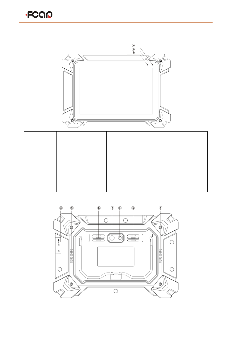
Tablet structure diagram
Serial
number
Name
Description
①
Power Indicator
Charging indicator
②
Microphone port
Voice input
③
Light sensor
External light intensity sensing

FCAR FD505 Wheel Alignment System User Manual
9
Serial
number
Name
Description
④
TF card slot / 3.5
headphone hole
Storage TF card location / headphone hole
⑤
Heat dissipation hole
For tablet cooling, avoid overheating
⑥
External horn hole
For external sound playback
⑦
Camera
For photography or video recording
⑧
Flash lamp
Used to provide light when light is weak
⑨
DC power port
For tablet charging or power supply
⑩
RJ45 interface
For network connection
⑪
USB interface (B
shape)
Device interface: used to connect computers
and use tablets as USB drives
⑫
USB interface
Host interface: for tablets to connect to other
devices or to connect to USB drives
⑬
HDMI interface
Standard HDMI interface: used to connect
HDTV output
⑭
Power switch
For on / off tablets, or for locking screens
1.4 Product functions and features
⚫High precision
5 high-resolution 2 million pixels ultra-clear industrial cameras, which can realize the
change of the wheel angle of the whole car. With higher accuracy, the compensation

FCAR FD505 Wheel Alignment System User Manual
10
calculation error is based on the change of the intermediate camera monitoring level.
Supported with double adjustment mode, wheel grounding adjustment, and wheel
suspension adjustment, both the front and the rear of the car can be measured.
⚫Wide sight
The sight of camera can be adjusted freely, solving the problem that traditional 3D
ultra-long, ultra-wide, ultra-narrow vehicles cannot measure.
⚫Specialization
The industrial-grade computer chip is faster and more accurate than the traditional
computer in image recognition and angle calculation, and the measurement data is
synchronized faster than 0.1 second. The position detection is rotated by rotating the target
to perfectly solve the measurement site limitation.
⚫Intelligentization
It can adapt to multi-port synchronous display such as Android tablet, Android TV
and subsequent Android mobile phone; dynamic loading display, stereo display is more
intuitive.
⚫Practicality
Applicable to all kinds of lifting platforms (double columns, four columns, small
scissors, large scissors), it solved the traditional 3D aligner lifting platform and site
restrictions; overseas version using air transport box with casters, single handling; through
WIF mode can directly communicate with the tablet, it can be demonstrated immediately
once powering up, and it is convenient and quick to install and operate.
2Selection and use of supporting tools
FCAR 5D four-wheel alignment system tools include high-precision fixtures, targets,
corner discs, etc. It will be introduced separately in the following.

FCAR FD505 Wheel Alignment System User Manual
11
2.1 The use of corner plate
The 5D four-wheel alignment system is equipped with two corner plates which
installed at the front wheel position of the car. Before driving, lock the corner plate with
the locking pin to prevent it from rotating. Do not remove the locking pin when measuring
the toe and inclination, so as to avoid measurement errors caused by wheel slip when
pushing the car. In order to make the wheels to rotate freely during the caster measurement,
the locking pins on both sides of the corner plate must be removed.
Note: When getting in the car, make sure the wheel is at the center of the
turntable.
2.2 Special fixtures and targets
This fixture is a four-claw special fixture designed for the testing of 5D four-wheel
alignment system. It has beautiful appearance and flexible use. The aligner is equipped
with 4 targets (2 short and 2 long), which mainly provide target graphic reflection for the
camera. The camera needs to be tested before testing to ensure that all four targets are
within the camera's viewable range.
FCAR FD505 Wheel Alignment System User Manual
12
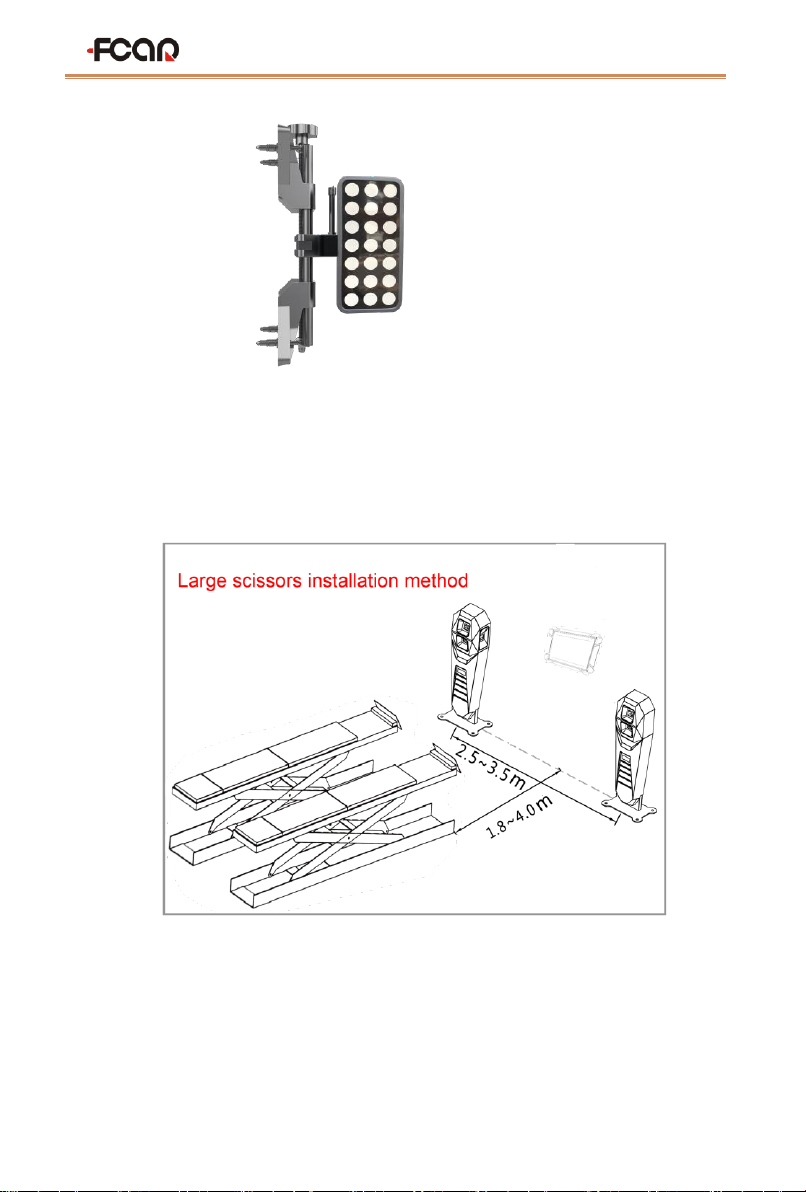
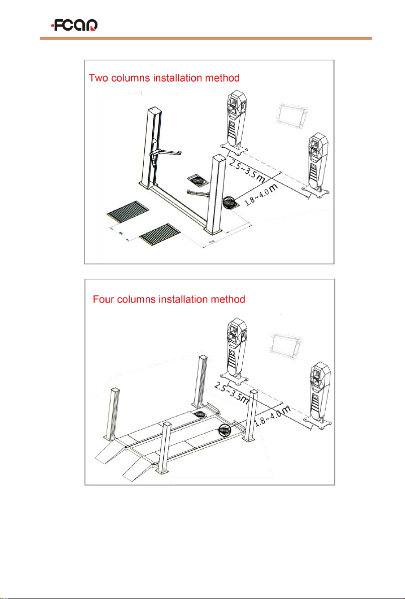
2.3 5D Four-wheel alignment system installation method
FCAR 5D four-wheel alignment system breaks through the limits of the field and is
suitable for a variety of lifting platforms (two columns, four columns, small scissor and
large scissors). The following are installation options:
Note: The small scissor installation scheme is similar to the large scissor
FCAR FD505 Wheel Alignment System User Manual
13
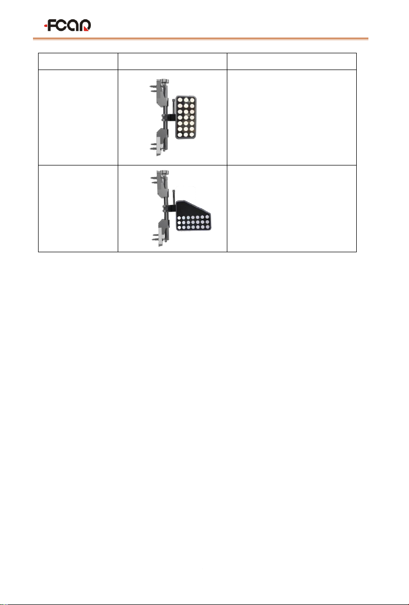
2.3.1Target selection
Please refer to the table below to select the target type according to different lifting
platforms:
FCAR FD505 Wheel Alignment System User Manual
14
Type
Physical view
Adaptation plan
Long target
large scissor/small scissor
installation plan
Trapezoidal target
Two columns installation plan,
four columns installation plan
Tip: the target type selection is complete and must be set in [System Settings], as shown
in Chapter 6.
3Preparations before wheel alignment operation
3.1 Preparation before operation:
1) Install the corner plate and lock the corner plate with the locking pin to prevent it
from rotating.
2) When driving the car, ensure that the tire is at the center of the corner plate. After
stopping the car, tighten the handbrake to ensure that the car does not move, and the
personnel are safe;
3) Check the rim size and tire pressure, the wear of the tires, the components status of
the steering system and the suspension system, such as the tie rod ball head, shock
absorber, etc. If there is excessive wear or unqualified component, please repair it
first. Then perform wheel alignment.
4) Knowing the origin of car, manufacturer, models and factory year.
5) When car pushing compensated and adjusted, please ensure the horizontal position

FCAR FD505 Wheel Alignment System User Manual
15
of the steering wheel and use the steering wheel holder to lock it, as shown in the
figure. When measuring and adjusting the caster measurement, pull the handbrake
and hold the foot brake.
Figure 3.1-1 Steering wheel holder installation
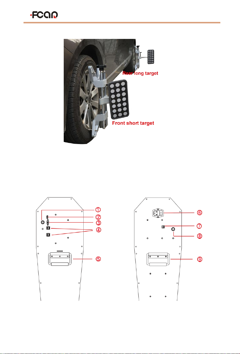
3.2 Fixture/target installation
FCAR 5D four-wheel alignment system is equipped with 4 fixtures, 4 targets and 2
hosts. The host must be installed in the front position of the head of vehicle in the left and
right direction (refer to the 5D four-wheel alignment installation method). The front wheel
should install two short rod targets separately and the rear wheel should install two long
rod targets separately.
➢How to install fixture/target
The fixture has been locked to the center position before leaving the factory. There is
no need to adjust the center and the fixture installation steps are as follows:
1) Rotate the hand wheel to make the claws fit to the diameter of the rim. The
installation direction of the clamp is shown in figure 3.2-1;
2) The clamp handle is up and perpendicular to the ground, and the four jaws should
stay to the edge of the rim closely;
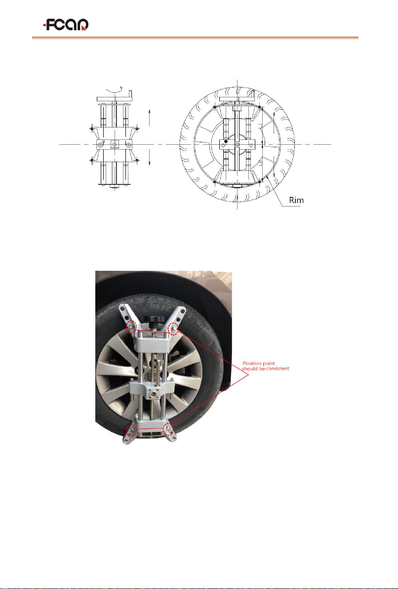
FCAR FD505 Wheel Alignment System User Manual
16
3) Rotate the hand wheel again to adjust and lock the clamp to the rim position.
Figure 3.2-1 Fixture installation
The physical photo is shown below:
Note: When assembling the fixture, the claws should keep away from the lead
block on the rim, please make sure that the four claws are in full contact with the
rim.
Installed long and short target object as shown below:
FCAR FD505 Wheel Alignment System User Manual
17
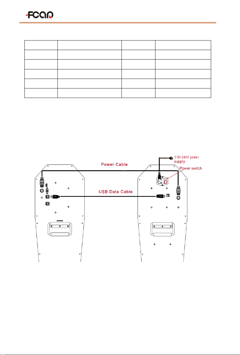
3.3 Device connection
The interfaces on the back of the main unit are as shown below:
FCAR FD505 Wheel Alignment System User Manual
18
Serial No.
Name
Serial No.
Name
①
Power interface
②
HDMI HD output
③
VGA interface
④
USB interface
⑤
Handgrip
⑥
Power interface
⑦
USB interface (B shape)
⑧
Power interface
⑨
Handgrip
Connect the two mainframes with the power cord and data cable of our factory
configuration as shown below. Connect the power plug to the standard three-terminal
power socket. The power supply requires 110~240V. Turn on the power switch to start the
two hosts.
3.4 Host on/off and function menu main interface
After the host is started, turn on the tablet. Since the tablet has been connected to
Wi-Fi of the router built in the host computer at the factory, the program can connect to
the host automatically. If not, you can manually select the connection according to the

FCAR FD505 Wheel Alignment System User Manual
19
Wi-Fi name identified on the host back. Run the program. the main function menu is
shown as figure 3.4-1:
Note: How to connect, please confirm whether the host is started, whether the
network is connected smoothly, or whether the Wi-Fi name is correct.
Figure 3.4-1 system main interface
The functions represented by each icon are shown in the table below:
Icon
Icon name
Function description
Target
monitoring
Before wheel alignment, camera monitoring must be
carried out to ensure that all targets are clearly within
the visual range of the camera
Select model
Select the model of the vehicle to be tested, and then
directly enter the cart compensation and the caster
measurement.

FCAR FD505 Wheel Alignment System User Manual
20
Fast
positioning
With this function, the maintenance technician can
quickly judge whether the relative position of the
camera and the target is correct or measure in the mode
without vehicle data
Maintenance
information
View, modify, print service records
System
settings
Device private settings, global system settings, shop
information settings, etc
Exit
Exit 3D four-wheel alignment system normally and
return to Android desktop
45D Four-wheel alignment system operation process
Before testing the wheel, the target should be monitored to ensure that the target is
complete clear within the camera viewable range. After the target monitoring is completed,
the vehicle pushing compensation and the caster measurement can be performed. If the
measured result does not meet the requirements of the standard database, the
corresponding adjustment should be made. After the adjustment is completed, a test run
should be carried out to check whether the abnormal condition of the vehicle is eliminated.
If the standard is not met, the measurement should be re-adjusted. The functions and
operation methods of FCAR 5D four-wheel alignment system will be specifically
introduced below.
The flow chart is as follows:
Table of contents
Other Fcar Diagnostic Equipment manuals


