Fcar FV100 Specification sheet

1
FCAR Product Manual
Statement
This manual is designed for the use of FCAR products; it cannot be copied or
stored in any form (electronic, mechanical, photocopying, recording or otherwise)
without prior written permission being secured from Shenzhen FCAR Technology
Co., Ltd.
This manual is intended for professional vehicle repair technicians.
This manual provides the operation methods for FCAR products only, and the
company accepts no responsibility for the consequences caused by attempting to
use the operation methods on other equipment.
The company shall not accept any responsibility for accidents caused either by the
user personally or anyone else, or costs and expenses due to equipment
damages including equipment loss caused by the user’s abuse or misuse,
arbitrary changes or repairs or operation of the equipment in a manner not in
accordance with the manual requirements.
This manual is written in accordance with the existing configuration and functions
of the product, and is subject to change without notice if the product adds new
configurations and functions.
If you have any questions, please contact us by the following ways:
Headquarters: 8F, Chuangyi Bldg., No. 3025 Nanhai Ave., Nanshan, Shenzhen, China
518060
Tel: 0086-755-82904730
Fax: 0086-755-83147605
E-mail: [email protected]
Website: http://www.fcar.com

2
FCAR Product Manual
Registered trademark
The company has registered the trademark in mainland China. The
company declares that the ownership of the registered trademark, service mark,
domain name, logo, and company name in countries in which they have not yet been
registered belongs to the company. Other products and their company name
trademarks mentioned in this manual belong to the original registered company. The
trademarks, service marks, domain names, logos, company names or other
companies mentioned may not be used without prior written permission of the owner.
FCAR Series Host Machine Maintenance and Use Cautions
Do not allow unauthorized disassembly.
Avoid strong impacts to the equipment.
Avoid proximity to any magnetic field.
Do not keep this machine in a high temperature environment for any length of
time.
Do not keep this machine in a low temperature environment for any length of time.
Do not forcefully click on the screen or click the screen with sharp tools.
Do not use water and chemical solvents to clean the machine, please use a soft
clean cloth and neutral detergent instead.
Automobile Inspection Notes
Follow the standard safety rules of the auto repair industry to operate. Be
especially careful to avoid impact or damage caused by environmental factors
such as the surrounding pH, poison gas or high pressure environment.
Vehicle battery fluid contains sulfuric acid, which is corrosive to the skin. During
the operation, avoid direct contact with the battery fluid, in particular being careful
not to splash into the eyes. Keep away from fire.
The engine exhaust gas contains a variety of toxic compounds, which one should
avoid breathing in. During the operation, park the vehicle in a well-ventilated

3
FCAR Product Manual
place.
When the engine is running, the temperature is very high; please avoid contact
with the water tank, exhaust pipe and other high temperature components.
Before starting the engine, apply the handbrake and place the shift lever in Gear
Neutral (Manual Transmission) or P (Automatic Transmission) to avoid sudden
movements of the vehicle when starting the engine.
Before repairing the vehicle, apply the parking brake, engage the Neutral or P
range, and lower the driver seat’s glass doors.
If the engine can be started, warm-up the vehicle to normal temperature (water
temperature is about 80 °C), and turn off the auxiliary electrical appliances (such
as air conditioning, lighting, sound, etc.).
Find the diagnostic socket of this car; check and confirm the diagnostic socket
cables are in good condition, connecting the main unit for diagnosis. Otherwise,
do not test, to avoid damage to the main unit. If necessary, use a multimeter to
measure the voltage of the diagnostic socket.

FCAR Product Instruction Manual
4
CONTENTS
PRODUCT INTRODUCTION .............................................................................. 6
Host Structure .............................................................................................6
VCI Box Structure......................................................................................... 8
HOST ON/OFF AND FUNCTION MENU............................................................. 9
Host Charging ..............................................................................................9
Booting ......................................................................................................10
Shutdown ..................................................................................................10
Introduction to Each Menu Option ...........................................................10
PREPARATION BEFORE DIAGNOSIS ............................................................... 13
Technical Requirements Before Diagnosis ................................................14
3.1.1 Equipment Requirements ...................................................................... 14
3.1.2 Vehicle Requirements............................................................................ 14
3.1.3 Technician Request................................................................................ 15
Vehicle Connection....................................................................................15
3.2.1 Connect VCI Box to Vehicle.................................................................... 15
3.2.2 HostandVCIBoxConnection ........................................................................ 17
Vehicle Models Selection ..........................................................................19
3.3.1 Manual Selection................................................................................... 20
3.3.2 Automatic Identification ....................................................................... 21
3.3.3 Direct Access to Vehicle System ............................................................ 21
3.3.4 Automatic Scan VIN Code...................................................................... 21
3.3.5 Manual Input VIN Code ......................................................................... 22
3.3.6 General OBD Access Mode .................................................................... 22
Diagnosis and Other High-Level Function .................................................22
3.4.1 Diagnostic Function Main Interface ...................................................... 23
Diagnosis ...................................................................................................24
3.5.1 Read Fault Code .................................................................................... 26
3.5.2 Erase Fault Cede.................................................................................... 27
3.5.3 Read Live Data ...................................................................................... 28

FCAR Product Instruction Manual
5
3.5.4 Actuation Test ....................................................................................... 31
Special Function.........................................................................................34
General OBDII............................................................................................35
CHINESE HD DIAGNOSIS................................................................................ 35
DETECT TOOLBOX ......................................................................................... 36
Node Screening .........................................................................................37
Pin Detecting .............................................................................................38
DATA MANAGEMENT.................................................................................... 39
REMOTE ASSISTANCE.................................................................................... 40
REFERENCE.................................................................................................... 41
UPDATE......................................................................................................... 41
SETTING ........................................................................................................ 42
Language ...................................................................................................42
Unit............................................................................................................43
User Info ....................................................................................................43
Self Test .....................................................................................................44
Activation ..................................................................................................44
Push...........................................................................................................45
Data Cleaning ............................................................................................46
About Us....................................................................................................46
System Setting...........................................................................................46
WARRANTY........................................................................................................ 47

FCAR Product Instruction Manual
6
Product Introduction
The product is an integrated automotive computer fault diagnostic instrument aimed at
the testing and diagnosis of gasoline, diesel, natural gas and other electronic control
systems. The product is applicable to large and small service companies, training
institutions, automobile manufacturers, repair stations, diesel engine manufacturers,
mining machinery, petrochemical, energy and other enterprises.
The software is comprehensively configured, and vehicle data and information in it are
authoritative and fully meet the strict requirements of customers' detection breadth and
depth. The software covers thousands of vehicle model data, and provides a powerful
help system with maintenance information, enabling users to deal with the problems in
practical work easily and quickly, thereby increasing the efficiency and technical level
and reflecting the advantage of professional level quality.
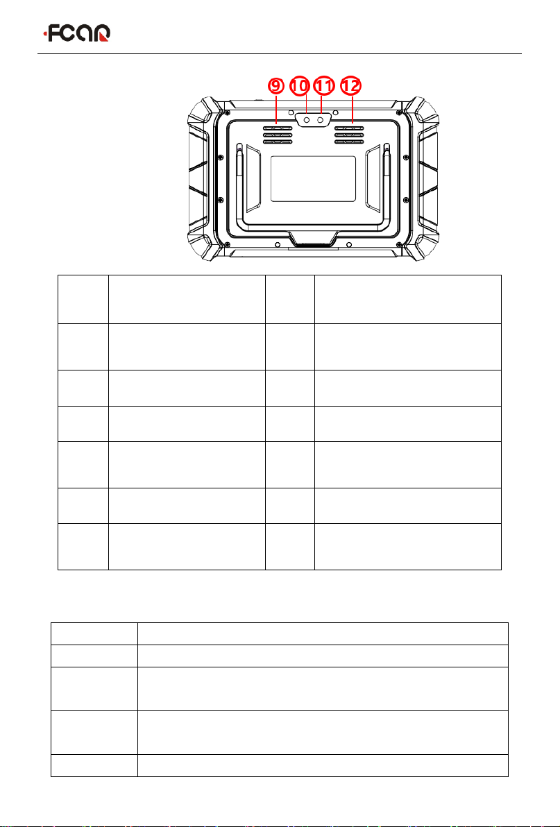
Host Structure
FCAR Product Instruction Manual
7
Serial
No.
Name
Serial
No.
Name
①
Power
indicator
②
Light sensor
③
DC power port
④
USB Type-C port
⑤
USB port
⑥
Power switch
⑦
SIM card
socket
⑧
TF card socket
⑨
Speaker port
⑩
Camera
⑪
Flash lamp
⑫
Heat dissipation
hole
Host parameter
System
Android11 multiple task operating system
Processor
Cortex-A55 RK3566 Quad-core, 1.8GHz architecture processor
Touch
screen
8” Multi touch capacitive screen, TP thickness:1.1mm
Memory
4GB RAM & 64GB ROM, besides supporting 64GB TF memory
card
Connection
Wi-Fi &Bluetooth 2.0/4.0
FCAR Product Instruction Manual
8
Camera
Rear camera 8 million pixels, supporting Autofocus
Battery
capacity
3.7V/10000mAh
Interface
USB(A Shape), USB(Type C), TF card slot, DC power interface,
SIM Card Socket(Reserved)
Size
282mm*184mm*36mm
Operation
Temparature
0℃to 40℃
Store
Temparature
-20℃to 60℃
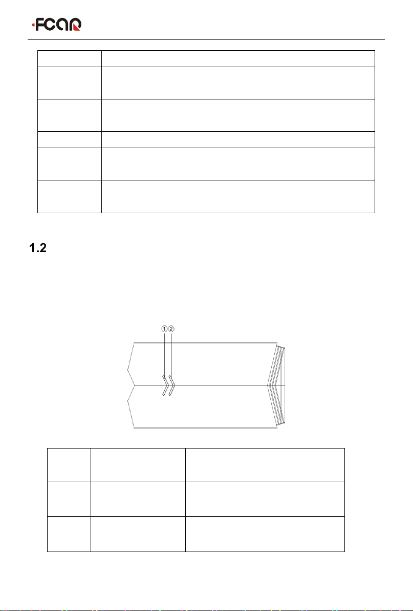
VCI Box Structure
Fcar offers a variety of VCI boxes. The functions and connection methods of each
model are similar. The following is an example of FV100.
FV100 Structure Description:
Serial
No.
Name
Description
①
Power indicator
Red light on when the power
supplied
②
Diagnostic
indicator
Green light flashes when
communicating with the vehicle
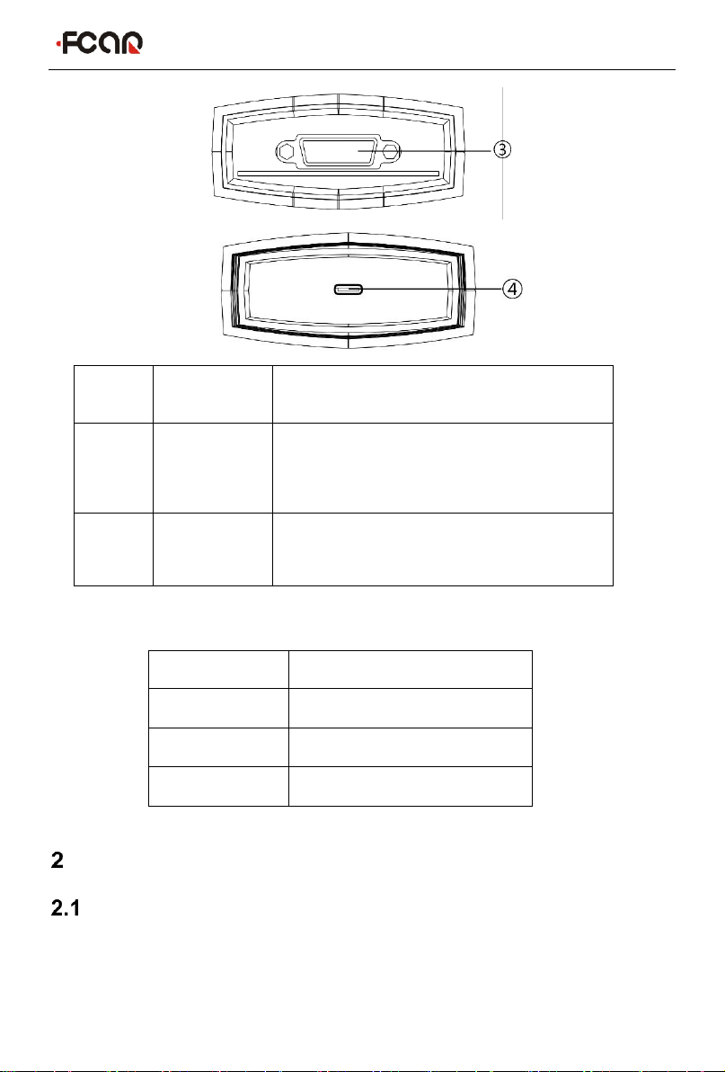
FCAR Product Instruction Manual
9
Serial
No.
Name
Description
③
DB15
Interface
Connect with the main test line and connect
the vehicle through the diagnostic
connector
④
USB
Type-C
Interface
Connect with tablet host or upgrade FV100
for use
FV100 Main Parameter:
Host On/Off and Function Menu
Host Charging
Host can be charged in the following way:
Power adapter: Plug one end of the AC/DC power adapter to the DC power port of the
host and then connect the other end to the wall socket. The power adapter can be
Processor
Cortex®-M3
Frequency
72MHZ
Bluetooth
V2.1+EDR, BT3.0, BT4.1
Memory
128KB
FCAR Product Instruction Manual
10
used to charge the built-in battery pack.
Note: Voltage of the power supply should be within the scope of the product host.
Exceeding the range may cause damage to the product.
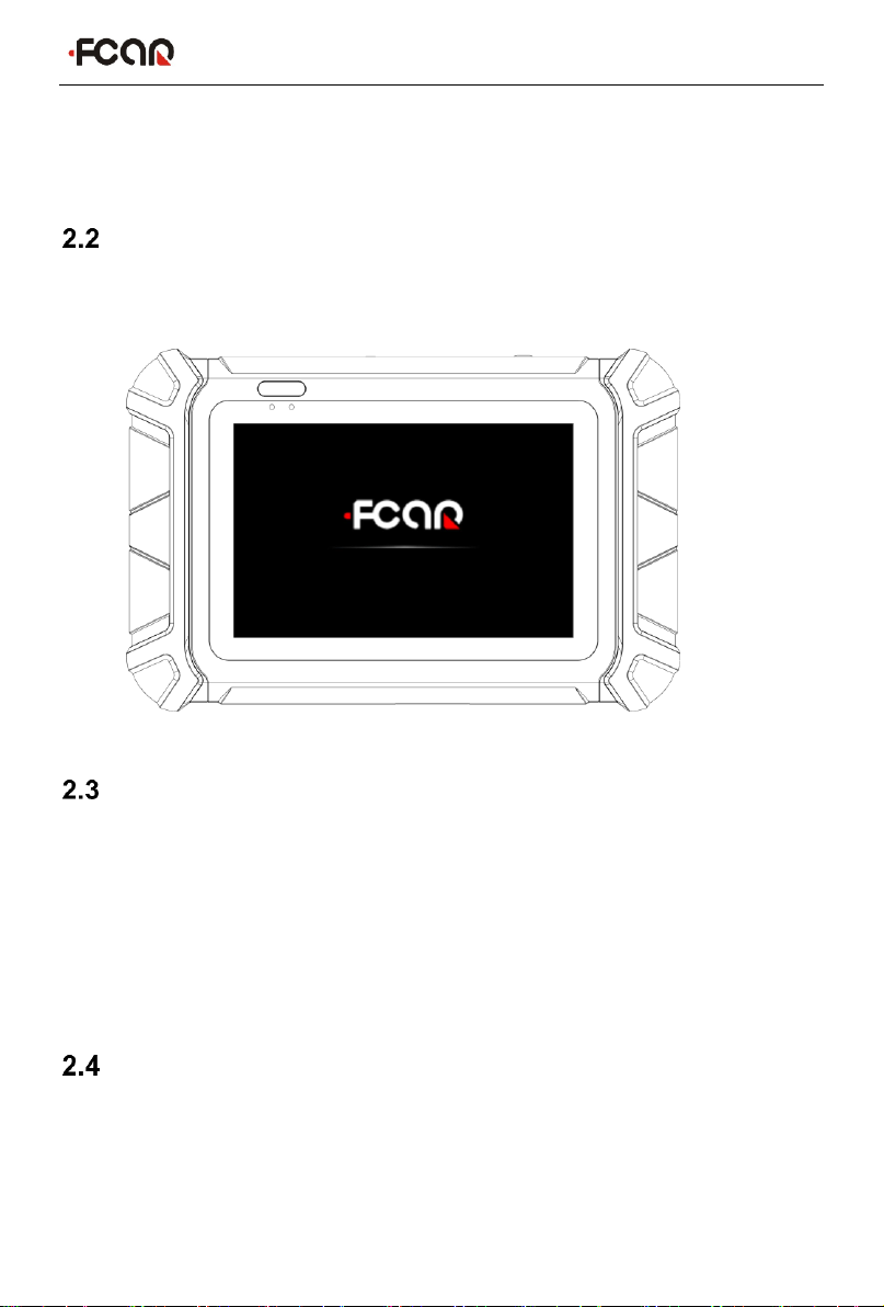
Booting
Press and hold the host power switch (about 3 seconds) to power on host, the
following welcome interface will pop up, and then system starts working.
Shutdown
All vehicle communication must be terminated before shutting down the diagnostic
equipment. Vehicle's electronic control module would go wrong if forced shutdown
during communication, please exit all diagnostic applications before shutting down.
The shutdown steps are as follows:
1) Short press the host power switch (about 2 seconds)
2) Click [Shutdown] in the pop-up prompt to close the host.
Introduction to Each Menu Option
After the system is powered on, enter the following main menu:

FCAR Product Instruction Manual
11
1) Status icon: is the default icon of the standard Android operating system
2) Toolbar (see Table 1 below)
3) Main menu (see Table 2 below)
4) Guide bar (see Table 3 below)
Tip: It is recommended to lock the screen whenever you are not using the device to
protect your system information and save battery power. Slightly click the power/lock
screen button once, the screen will be automatically locked. Excessive force or long
press may cause the button to malfunction or enter the shutdown interface.
Table 1: Toolbar
Icon
Function
name
Function description
VCI
Connection
VCI box connection and status display
(always available throughout diagnostic
operation)

FCAR Product Instruction Manual
12
Screenshot
One click to capture the current visual screen
(always available throughout the diagnostic
operation)
Settings
"Settings" function shortcut
Table 2: Main Menu
Icon
Function
name
Function description
Diagnosis
Vehicles diagnostic procedure
Chinese HD
Diagnosis
Chinese heavy diesel vehicles diagnosis
procedure
TPMS Tool
The application of the Fcar Tire Pressure
Activation Tool device
Detect
Toolbox
Provide detecting tools
Data
management
Browse and manage data files stored
Remote
Run this program to establish remote assistance
with FCAR after-sales technical team
Reference
guide
Provide help information such as equipment usage
instructions, maintenance assistance, trouble code
inquiry, etc
Update
Online upgrade of system software, model
software, etc
Settings
Set up and view system information
FCAR Product Instruction Manual
13
VCI
connection
Establish and manage communication connections
with VCI devices
Table 3: Guide bar
Icon
Function
name
Function description
volume
reduction
Turn down the tablet volume
Back
Return to last interface
Homepage
Return to the main interface of the Android system
Recently
used program
Display the list of recently-used program
thumbnails list, click on the program thumbnail to
open the program, and swipe up the program
thumbnail to close the program
Volume
amplification
Turn up the tablet volume
Preparation before Diagnosis
Through having established data connection with the vehicle's electronic control
system that has been connected to the VCI device, the diagnostic program can read
vehicle diagnostic information, check the data stream, and perform actuation test and
other functions.
To establish good communication between the diagnostic program and the
vehicle, you need to do as below:
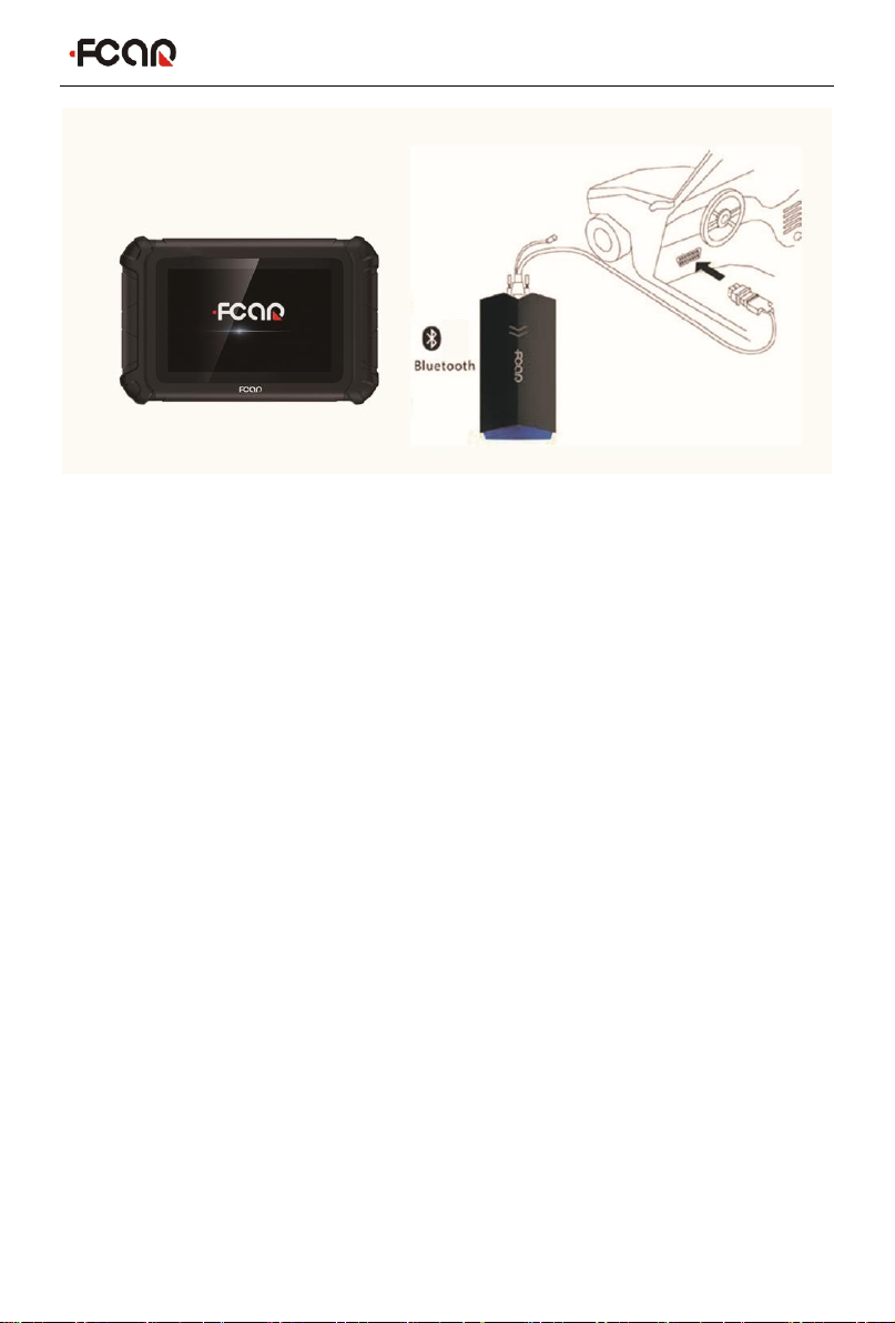
1) Connect the VCI box to the vehicle diagnostics socket and supply the power;
2) Establish communication between the VCI box and the host via Bluetooth pairing
or USB data cable;
3) Check VCI connection status in the upper right corner of the screen (see 3.2.2).
FCAR Product Instruction Manual
14
The vehicle diagnosis can be performed after the connection.
How to perform the Vehicle diagnosis
1) Establish a good communication between the diagnostic program and the vehicle
under test, see 3.2
2) Select vehicle type, see 3.3.
3) Perform vehicle diagnosis by “Auto Scan” all systems of the vehicle or manually
selecting and detecting a designated control unit. For details, see 3.5.
Here we make the detailed instructions.
Technical Requirements Before Diagnosis
3.1.1 Equipment Requirements
The device is equipped with a host and various test connectors when leaving factory.
In testing, please select appropriate test connector according to the type of vehicle
diagnosis socket.
3.1.2 Vehicle Requirements
Turn ignition switch to gear ON;
Vehicle battery voltage should be between 11~14V or 24~27V (subject
to the vehicle's power supply)
Accelerator pedal is in OFF state, that is, the idle coupling point;
Ignition timing and idle speed value should be within the standard
FCAR Product Instruction Manual
15
range, and the water temperature and transmission oil temperature are
in the normal working temperature (water temperature 90~110°C,
transmission oil temperature 50~80°C);
Then, diagnostic cable is connected properly.
3.1.3 Technician Request
Must have a basic knowledge of automotive electronics;
Understand the basic operation methods of this product and familiarize
with this manual;
Basically distinguish whether it is a mechanical fault or an electronic
control fault from the vehicle fault phenomenon tested;
Learn about the vehicle's origin, year of production, model, engine
model and more.
Vehicle Connection
3.2.1 Connect VCI Box to Vehicle
Before VCI box connected to a vehicle, it is necessary to judge whether the
diagnostic socket of the test vehicle is a standard OBD-II port or a non-standard
OBD-II port.
For vehicles with a standard OBD-II port: Connected the VCI to the vehicle
FCAR Product Instruction Manual
16
diagnostics socket directly.
For vehicles with a non-standard OBD-II port: Need to add a corresponding
connector to adapt the port; some other vehicles need to supply power to the
VCI box through other power sources of the vehicle.
Standard OBD-II port connection:
Instructions:
1) Determine the location and the port of the diagnostic socket;
2) Connect one end of main test cable to DB15 connector of the VCI box and fasten
the fixing bolt;
3) Connect the other end of the main test cable to the vehicle diagnostic socket;
4) At this time, the VCI box is powered by the vehicle diagnostic socket, and the
power indicator light is on.
Note: After test is completed, please rotate the fixing bolts and then gently
unplug the main test cable to avoid damage to the diagnostic port.
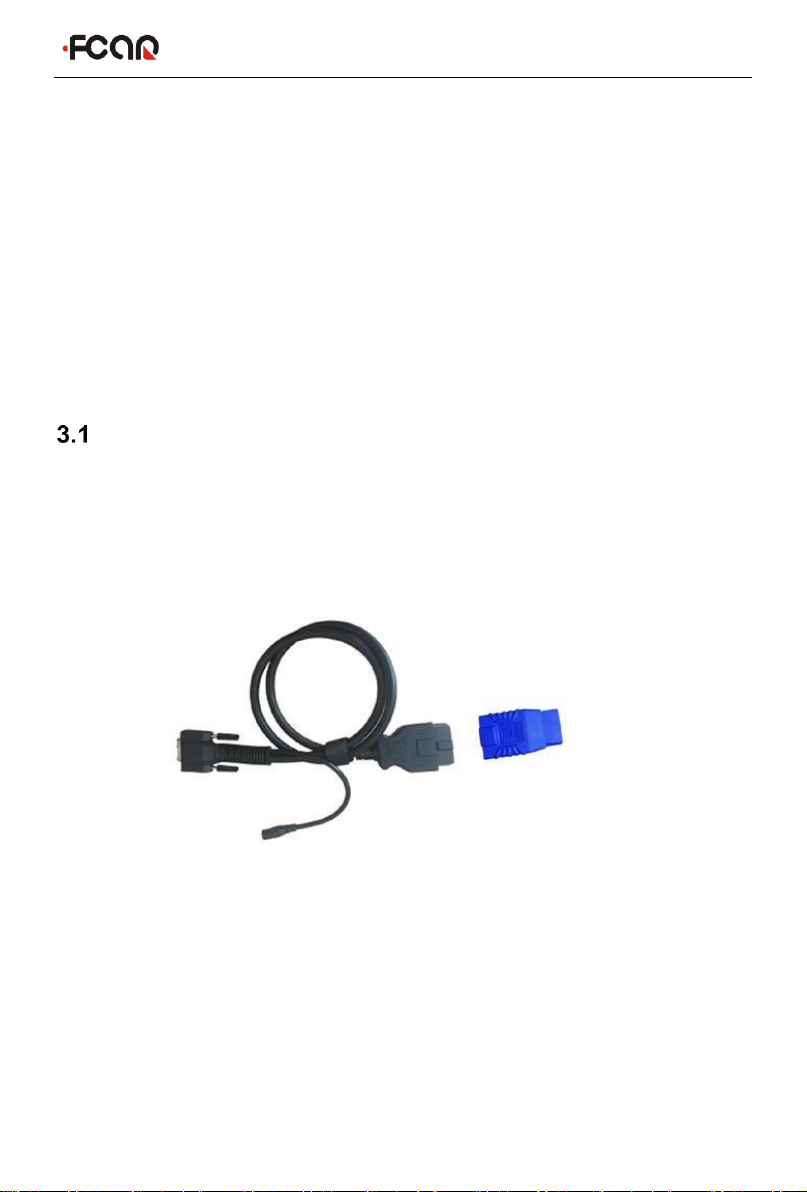
NON-OBD-II PORT CONNECTION
For vehicles connected to non-OBD-II interfaces, need to connect the main test cable
to their corresponding dedicated connectors, as shown in the figure below.
FCAR Product Instruction Manual
17
Instructions:
1) Determine the location, the port, and whether need to be connected to external
power source of diagnostic socket;
2) Connect one end of the main test cable to the DB15 connector of the VCI box
and lock the fixing bolts;
3) Connect the other end of the main test cable to a dedicated adaptor
corresponding to the vehicle;
4) Connect the dedicated connector that is connected to the main test cable to the
vehicle diagnostic socket;
5) At this time, VCI box is powered by the vehicle diagnostic socket, and then power
indicator light is on (if it is not lit, it may be because the vehicle diagnostic socket
is not energized, you can energize the VCI box by the cigarette lighter or the
battery clip).
3.2.2 Hostand VCIBox Connection
After VCI box is connected to the vehicle, the connection between the host and the
VCI box needs to be matched, and then vehicle diagnosis can be started after
matching is completed; the VCI box supports two ways of communicating with the
FCAR Product Instruction Manual
18
host: Bluetooth pairing and USB cable.
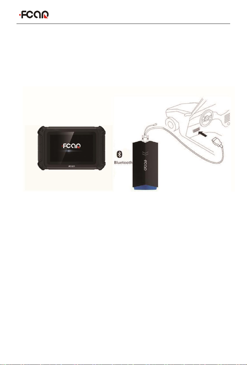
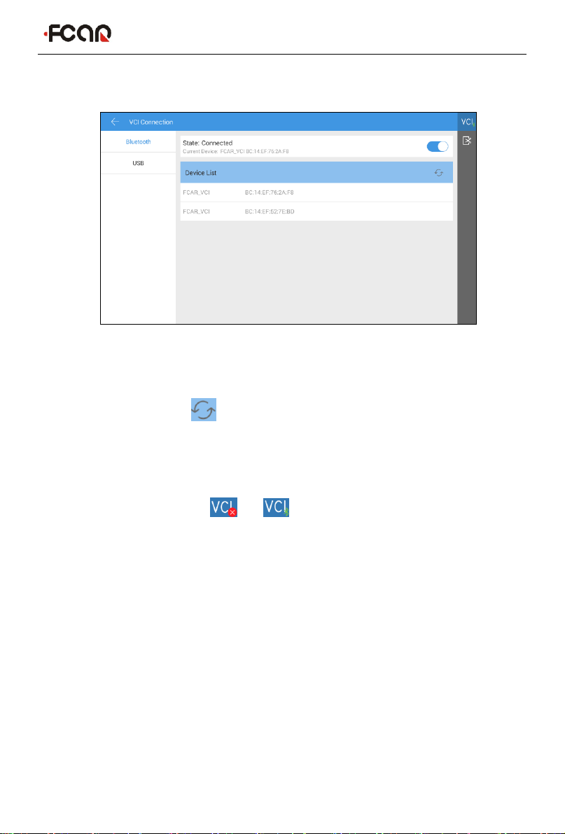
Paired through Bluetooth
1) Turn on the host power supply;
2) Select [VCI Connection] in the main menu; select [Bluetooth] in the connection
mode;
3) Click the Scan icon on the right side of the device to automatically scan
Bluetooth devices nearby.
4) Select target Bluetooth to match;
5) When matching is completed, state of VCI icon in the upper right corner of the
screen changes from " " to " ", indicating that the Bluetooth pairing is
successful and the vehicle diagnosis can be started.
Note: If the signal strength of the transmitter is too weak, Bluetooth device
can't be searched. In this case, please move it as close as possible to the VCI
Bluetooth device.
Through USB cable connection

FCAR Product Instruction Manual
19
USB connection is the fastest communication method between the host and the VCI
device. Please use dedicated USB cable configured by our factory to connect. After
the connection is completed, state of VCI icon in the upper right corner of the screen
changes from “ ” to “ ”. , indicating that the USB connection is successful, and
then the vehicle diagnosis can be started.
Note: These two connection methods can't be used at the same time!
Vehicle Models Selection
When all the above connections are completed, click [Diagnosis] on Main Menu to
start the vehicle diagnosis. The following figure shows the gasoline version of the
vehicle selection interface. The other versions of the model interface are similar.
FCAR Product Instruction Manual
20
1) Toolbar (see Table 1 below)
2) Regards to model manufacturer and related detection functions, click on
“ ” in upper right corner of the model to view function list and other
related information of the vehicle type.
3) Asian, European, American major brand vehicle series selection menu
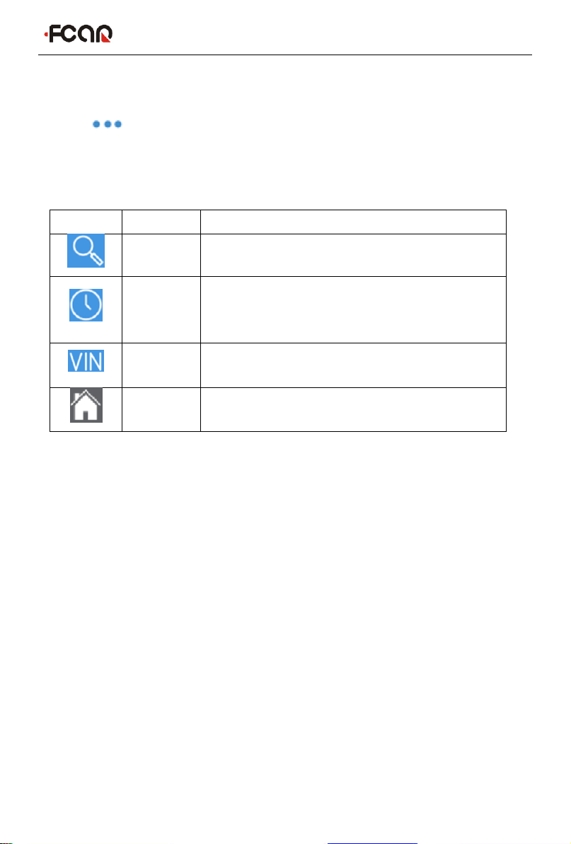
Table 1:
Icon
Name
Function description
Search
One-click search for major brand vehicle types
History
record
View maintenance history, quick access to
diagnostics, view diagnostic List, model version
information, and more
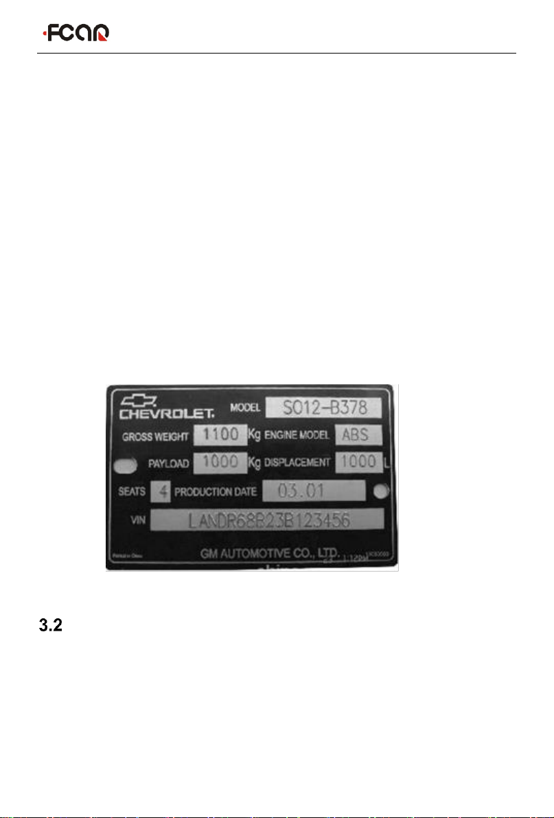
VIN code
Identify the vehicle types by manually or
automatically scanning the VIN code
Homepage
Return to Main Menu
Diagnostic program requires “Car Selection” before entering the system module
diagnostic function. The device can do vehicle identification in the following ways:
1) Manual selection
2) "Auto Selection" function
3) Direct access to the vehicle system module
4) Automatically scan VIN code
5) Manually input VIN code
6) Access via OBD
3.3.1 Manual Selection
Manual Vehicle Selection uses menu guide mode, just follow the on-screen
instructions to make a series of selections, and then specific options will vary
depending on the model being tested. Among a large number of vehicle types, you
can even quickly find the target brand through search function of the toolbar, and
then select according to the screen prompts; for gasoline models, you can find the
Other manuals for FV100
1
Table of contents
Other Fcar Diagnostic Equipment manuals


Popular Diagnostic Equipment manuals by other brands

Hella Gutmann
Hella Gutmann macsRemote operating instructions

Barco
Barco MDCC-4230 user guide

Airmar Technology Corporation
Airmar Technology Corporation TDT1000 owner's guide

Bosch
Bosch EPS 708 Repair instructions

American Diagnostic Corporation
American Diagnostic Corporation AD View 2 Assembly instructions

MSW Motor Technics
MSW Motor Technics MSW-CA-116 user manual


