FEAS SNT150-K User manual
Betriebsanleitung
Bitte sorgfältig beachten!
Operating
instructions
Please observe carefully!
Für die Modelle: to apply for:
- konform
GmbH
Postfach 1521
D - 22905 AHRENSBURG
Telefon: 04102 - 42082
Telefax: 04102 - 40930
www.feas.de
©2021
®
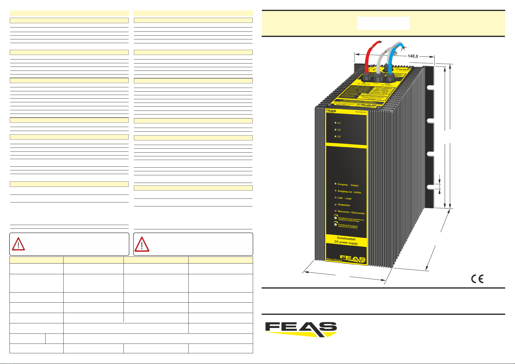
SNT150-K
SNT15012-K SNT15024-K SNT15048-K
Schutzeinrichtungen
nicht erforderlich, da kurzschlussfest
im Gerät integriert
Ausgangssicherung
Überlastschutz
Eingangsgrößen
320 - 550V (44-66Hz)
AC
350 - 550V (44-66Hz)
AC
450 - 780VDC
bei 400VAC max. 1,75A / max. 2,25A (SNT15048)
<15,0 A bei 400VAC
Transientenüberspannungsschutz-Varistor
Gasableiter gegenüber PE
Eingangswechselspannung (3-Phasenbetr.)
Eingangswechselspannung (2-Phasenbetr.)
Eingangsgleichspannung
Stromaufnahme bei Nennlast
Einschaltstromstoß
Schutzbeschaltung
Sicherheitsdaten
Prüfspannung Trafo
5kV gemäß VDE0570
AC
Hochspannungsfestigkeit
Eingang/Ausgang 4kV nach VDE0806/IEC380
AC
Funkentstörgrad
gemäß VDE0871B, EN55022/B
95% relative Feuchte im Jahresdurchschnitt
Betauung möglich - tropentauglich
Schutzklasse
Umgebungsfeuchte
Schutzart Gehäuse
Schutzklasse I mit PE-Anschluss (EN62368-1)
Schutzart Klemmen
-
Rüttelfestigkeit
>50g bei 33Hz in X, Y und Z
nach IEC68 und DIN41640
Schutzkleinspannung
PELV (EN60204), SELV (EN62368-1)
Betriebsdaten
100% (Dauerbetrieb)
-40°C bis +80°C
Einschaltdauer (ED)
Arbeitstemperaturbereich
-40°C bis +105°C
Ja
ab 40°C
Lagertemperaturbereich
Parallelschaltbar
Leistungsabweichung bei Temperatur
natürliche Konvektion
Kühlung
Wirkungsgrad
Aufstellungshöhe
MTBF
unbegrenzt
> 380.000h
Angewandte Bauvorschriften
CSA/UL
CSA-C 22.2 / Ul60950, Ul508, UL1950
gemäß VDE
IEC
EN
VDE0100, VDE0110, VDE0113, VDE0551,
VDE0160/W2, VDE0806
IEC62368-1, IEC61000-6-1-2-3-4, IEC60068-2-3,
EN62368-1, EN61140, EN61000-6-1, EN61000-6-2,
EN61000-6-3, EN61000-6-4, EN55022, EN55011
EN61000-3-2, EN61000-3-3, EN50204, EN60204
EN60529, EN61000-4-2-3-4-5-6-8-11, EN60068-1,
EN6068-2-1-2-3-6-27-30, EN45501, EN50021,
EN61558-2-17, EN50178
IEC60068-2-11-52, IEC60529, IEC380
Ausgangsgrößen
siehe Tabelle unten
siehe Tabelle unten
einstellbar 0,5 ... 1,5 x INenn
Ausgangsspannung UNenn
Ausgangsstrom INenn
Strombegrenzung / Fuse Mode
Leistung
Restwelligkeit
siehe Tabelle unten
<50mVrms
Einstellbereich
siehe Tabelle unten
Technische Daten
Safety devices
not necessary - short circuit proof
integrated into device
Fuse for output
Overload protection
Input data
320 - 550V (44 - 66Hz)
AC
350 - 550V (44 - 66Hz)
AC
450 - 780VDC
at 400VAC max. 1.75A / max. 2.25A (SNT15048)
< 15.0 A at 270VAC
Transient voltage suppressor Varistor
surge arrester against PE
AC input voltage (3-phase-mode)
AC input voltage (2-phase-mode)
DC input voltage
Input current at nominal load
Input current peak
Protective circuit
Safety data
Test voltage transformer
5kV according to VDE0570
AC
High voltage resistance
Input/Output 4kV according to VDE0806/IEC380
AC
Degree of EMI suppresion
according to VDE0871B, EN55022/B
95% relative humidity, yearly average
dewing allowed for use in tropical ambient
Protection class
Ambient humidity
Protective class enclosure
Protection class I with PE-Connection (EN62368-1)
Protective class terminals
-
Vibration proof
>50g at33Hz in X, Y and Z
acc. IEC68 and DIN41640
Extra low safety potential
PELV (EN60204), SELV (EN62368-1)
Operating data
100%
-40°C to +80°C
Duty circle
Operating temperature range
-40°C to +105°C
Yes
from 40°C
Storage temperature range
Parallel connection
Derating
selfcooling
Cooling
Efficiency
Installation altitude
MTBF
unlimited
> 380.000h
Applied construction regulations
CSA/UL
CSA-C 22.2 / Ul60950, Ul508, UL1950
according to VDE
IEC
EN
VDE0100, VDE0110, VDE0113, VDE0551,
VDE0160/W2, VDE0806
IEC62368-1, IEC61000-6-1-2-3-4, IEC60068-2-3,
EN62368-1, EN61140, EN61000-6-1, EN61000-6-2,
EN61000-6-3, EN61000-6-4, EN55022, EN55011
EN61000-3-2, EN61000-3-3, EN50204, EN60204
EN60529, EN61000-4-2-3-4-5-6-8-11, EN60068-1,
EN6068-2-1-2-3-6-27-30, EN45501, EN50021,
EN61558-2-17, EN50178
IEC60068-2-11-52, IEC60529, IEC380
Output data
see table below
adjustable 0.5 ... 1.5 x INominal
Output voltage UNominal
Output current INominal
Current limiting / Fuse Mode
Power
Residual ripple
<50mVrms
Range of adjustment
Technical Data
Verbraucher (z.B. Schütze, Motoren, Magnetventile, etc.)
die nicht ordnungsgemäß nach den relevanten
Richtlinien entstört sind (z.B. Varistoren, RC-Glieder,
etc), können zur Störung bzw. Zerstörung des
Netzgerätes führen.
Consumers (e.g. contactors, motors, solenoid valves
etc.) which have not been correctly interference-
suppressed in accordance to the relevant guidelines
(e.g. varistors, RC elements, etc.) may cause power
supply regulation to malfunction.
Vorsicherung (techn. nicht erforderlich) Fuse for input (technically not necessary)
siehe Tabelle unten
see table below
see table below
see table below
see table below
see table below
siehe Tabelle unten
Typ
Ausgangsleistung Nenn/Boost
Output-power Nom./Boost
10,0 - 15,0VDC
SNT15012-K
45,0A
540 / 810 Watt
92%
Ausgangsstrom INenn
Output current INominal
Wirkungsgrad
Efficiency
Maße
Dimensions
Gewicht
Weight ca. 10,2kg
BxHxT
BxHxD
23,0 - 30,0VDC
SNT15024-K
148mm x 256mm x 167,5mm
25,0A
600 / 900 Watt
93%
ca. 10,2kg
Einstellbereich der
Ausgangsspannung
Range of adjustment
output voltage
Vorsicherung
Fuse for input
bei 400VAC 3,0Amp. träge
at 400VAC 3.0Amp. delayed
48,0 - 60,0VDC
SNT15048-K
15,0A
720 / 1080 Watt
94%
ca. 10,2kg
Ausgangsspannung UNenn
Output voltage UNominal 12VDC 24VDC 48VDC
bei 400VAC 4,0Amp. träge
at 400VAC 4.0Amp. delayed
IP65 - IP69K* (* zu IP69K siehe Kapitel 9) IP65 - IP69K* (* for IP69K please see section 9)
148,0
256,0
8,2
167,5
114,0
230,0

1. Funktionsweise
Das SNT150-K ist ein Schaltnetzteil zur Speisung von
Verbrauchern aus dem Niederspannungsnetz. Die
Kühlung erfolgt über Luftkonvektion am Gehäuse-
Kühlprofil. Bitte die “Derating-Kurve” beachten.
1. Mode of operation
The SNT150-K is a power supply to supply consumers
from low voltage network.The cooling of the device
takes place via air convection at the case heatsink.
Please observe the derating diagram.
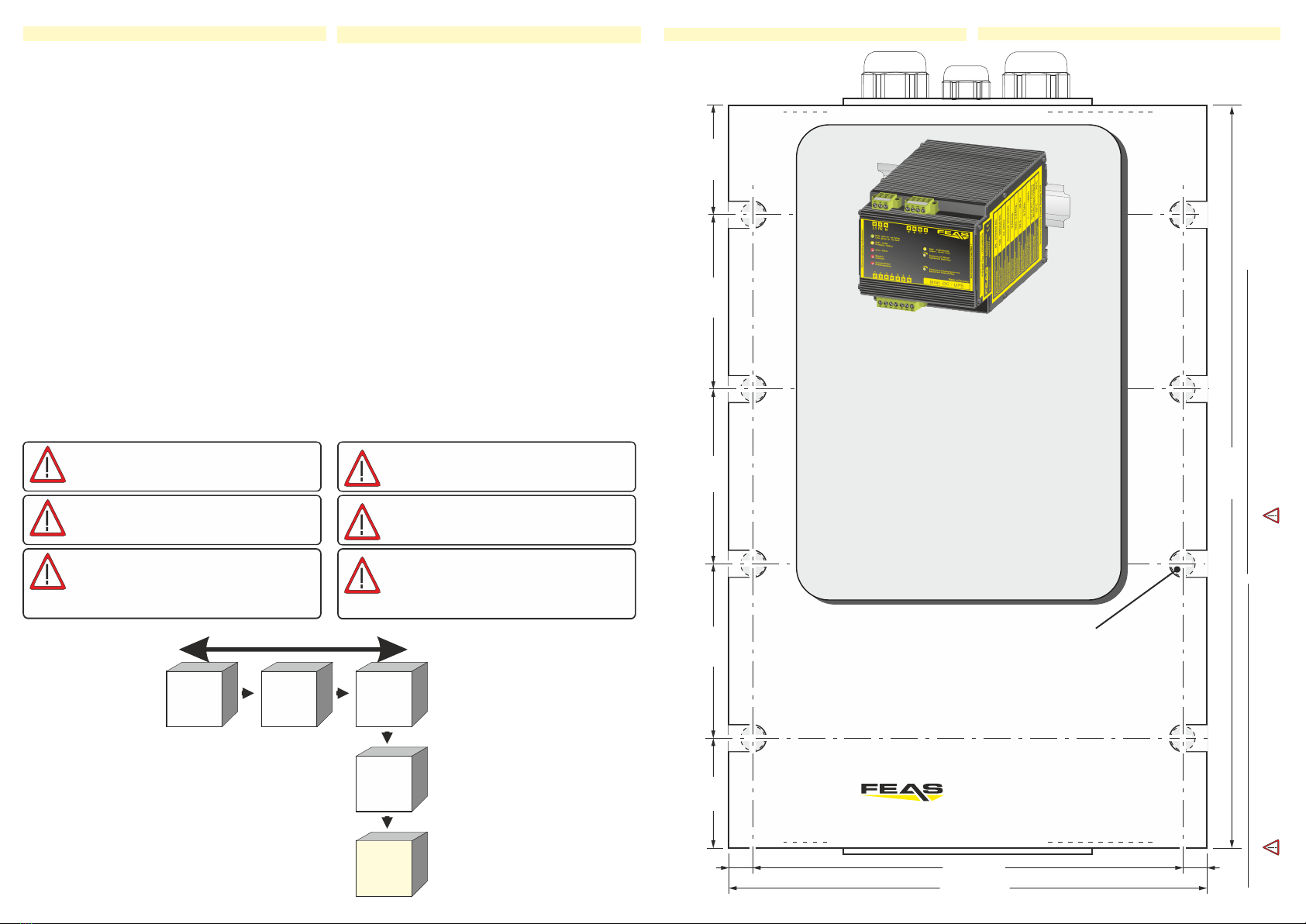
2. Montage
Das SNT150-K kann mit sechs M8-Schrauben an eine
Wand geschraubt werden. Hierzu bitte die Bohrmaße
auf der letzten Seite beachten.
ACHTUNG! Zur besseren Wärmeabfuhr sollte das
Gerät einen Freiraum von 15mm haben.
2. Installation
The SNT150-K can be mounted on a wall with six M8-
screws. Take notice of the drilling dimensions on the
last page.
CAUTION! For improved heat dissipation, the device
should have a minimum free space of 15 mm.
3. Elektrischer Anschluss
Das Gerät laut Anschluss-Schema unten anschließen.
Hierbei unbedingt die allgemeinen
Sicherheitsvorschriften beachten. Unsachgemäßer
Anschluss kann zu einem Defekt des Gerätes führen.
3. Electrical connection
Take care of a correct electrical connection. Take the
wiring diagram at the bottom of this side as help.
Inappropriate connection can lead to a defect of the
device.
Normalbetrieb - Standard function Schlafmodus - Standby
Das Gerät wird durch Setzen einer
Brücke zwischen Pin 4 und 5 in den
Schlafmodus versetzt. Es befindet
sich im Bereitschafsmodus, ist aber
von der Last getrennt.
The device is switched to sleep mode
by setting a bridge between pins 4
and 5. It is in standby mode but
disconnected from the load.
Feineinstellung der Ausgangsspannung
Diese sollte nicht im Fuse-Mode
erfolgen!
Fine-adjustment of Output voltage
This should not be made in Fuse
Mode
Feineinstellung der Ausgangs-
Strombegrenzung
Fine-adjustment of Output current
limitation
interne Relais-
Belegung
internal relays
assignment
SNT150-K
1
2
3
Reset
SNT150-K
1
2
3
+
-
Uout
+
-
Verbraucher
consumer
Only charge accumulators or
rechargeable batteries!
Nur Akkus oder wieder-
aufladbare Batterien laden!
0,4
0,2
0
0,6
1,0
20100 30 50 70 90 10040 60 80
0,8
1,2
1,5
T / C°
Temperatur in Celsius
Ausgangsstrom
Output current
Iout
Inenn
Dauerbetrieb
Boostbetrieb
Powerboost
Derating
3 - Phasen
Wechselstromeingang
AC Input
DC Input
Gleich-
strom-
eingang
+
-
Kontaktbelastung der Relais:
- max. Schaltstrom 3,0 Amp.
- max. Schaltspannung 30V
Contact-load of the relays:
- max. switched current 3.0Amp.
- max. switched voltage 30V
!
Bei Stromentnahme von
mehr als 25A muss der
Strom gleichmäßig über
alle Ausgangsklemmen
verteilt werden.
If the output current exceeds
25A, the output current has to
be uniformly distributed over
the whole output terminals.
!
4. LED Anzeigen 4. LED Display
LED-Anzeigen / LED-Display
Last freigegeben
load switched on
Phase ausgefallen
Loss of L1 / L2 / L3
Nominallast
nominal load
Temperatur OK
Temperature OK
Laststrom OK
load current OK
Phase vorhanden
Input OK
Temperatur kritisch
Temperature critical
Überlast
Overload
Last getrennt
load switched off
L1, L2, L3
Ausgang - Output
Ausgang - Inhibit
Last - Load
Temperatur
Überstrom -
Overcurrent
green
green
green
green
green
green
red
red
Ausgang - Output
Ausgang - Output Temperatur
red flashing
yellow
flashing red
flashing
Kurzschluss, Last getrennt
Short circuit, load switched off
Übertemperatur, Last getrennt
Over-temperature, load switched off
Überstrom -
Overcurrent
Ausgang - Output redred Notaus nach dauerhaftem Kurzschluss
emergency stop after permanent short circuit
+
=
=
Überstrom -
Overcurrent
Ausgang - Output red flashingred flashing FuseMode ausgelöst, Last getrennt, Standby
FuseMode triggered, load switched off, standby
+=
Inhibit
+off
Schlafmodus / Standby Ausgang -
Inhibit
Ausgang - Output yellowred +
Fehlermeldungen / Error messages
keine Eingangsspannung
no Input
off
Last nicht freigegeben, Schlafmodus aktiv
load switched off, standby active
Last freigegeben, kein Schlafmodus
load switched on, no standby
kurz vor Kurzschluss, Überlast, Fusemode
transition to short circuit, overload, fuse mode
Ausgang - Output red Überlast, Last getrennt
Overload, load switched off
+
=
+
red
Temperatur zu hoch
Temperature to high
red
yellow
yellow
yellow
red
Überstrom -
Overcurrent Load off
Ausgang
Inhibit off
Inhibit yellow
+
=
+
+
5. Fehlermeldungen und Reset des Gerätes
q Phasenausfall
q Kurzschluss
q Notaus nach dauerhaftem Kurzschluss
q Geräteübertemperatur (max. 85°C)
q Überschreiten der Strombegrenzung
q Überschreiten des für Fuse Mode eingestellten
Wertes
Nach Notaus oder Überschreiten eines dieser
Parameter wird eine Fehlermeldung (siehe Punkt 4)
angezeigt und zum Schutz der angeschlossenen
Systeme die Last vom Gerät dauerhaft getrennt.
Zum Neustart des Gerätes ist dieses zu resetten,
dazu werden Pin 4 und Pin 5 kurzzeitig gebrückt.
5. Error messages and reset of the unit
q Phase loss
q Short circuit
q Emergency stop after permanent short circuit
q Critical and too high temperature (max. 85 ° C)
q Overload above Current limiting
q Exceeding the value set for Fuse Mode
After emergency stop or if one of these parameters is
exceeeded, an error message is displayed (see item
4). For protecting the connected systems the load of
the device is permanent switched off.
For restarting the unit you have to reset it by bridging
Pin 4 and Pin 5 for a short time.
Anschlussschema / Wiring diagram
!
Feineinstellung der
Ausgangsstrom-
begrenzung
Fine-adjustment of
Output current
limitation
Feineinstellung der
Ausgangsspannung
Fine-adjustment of
Output voltage
Auf Ladeschlussspannung der Batterie einstellen!
Adjust to maximum peak voltage of battery!
!

Überlast & Überschreiten der Strombegrenzung - Overload & exceeding current limit
Die Zeit bis zum Abschalten der Last variiert je
nach Stromstärke (siehe Diagramm unter Punkt 8).
Kurz vor Überlast leuchtet die LED Last rot.
Nach dem Überschreiten geht die LED Last aus
und die LEDs Ausgang und Überstrom leuchten
rot.
Achtung: Die LED Überlast gilt für die nominale
Ausgangsspannung (siehe Technische Daten).
Bei höherer Spannung findet eine tatsächliche
Überlast bereits bei geringeren Lastströmen statt.
Bei Überschreiten der über den Drehregler
eingestellten Stromgrenze leuchten die LEDs
Überstrom und Ausgang rot.
Die Last wird getrennt.
The time until the load is switched
off varies depending on the current
(see diagram point 8).
In transition to overload the LED
Load lights up red.
After exceeding the LED Load
switches off and the LEDs Output
and Overcurrent light up red.
Caution: The LED Overload applies
to the nominal output voltage (see
technical data).
At higher voltages, an actual overload
occurs even at lower load currents.
If the set current limit is exceeded
the LEDs Overcurrent and Output
glow red. The load is swithed off.
interne Relais-Belegung
internal relays assignment
SNT150-K
1
2
3
Temperatur ist im kritischen Bereich - Temperature is in critical range
Übertemperatur erreicht - Over-temperature is reached
Wenn im Gerät die Temperatur über 75°C steigt, wird
der Relaiskontakt 3 geöffnet. Sie haben somit die
Möglichkeit, z.B. eine externe Lüftung zu aktivieren.
Das Relais bleibt solange geöffnet, bis ein normaler
Temperaturbereich erreicht wird.
If the device temperature rises above 75°C, the
relay 3 opens. You have the opportunity, for
example to activate an external cooling. Relay-
contact 2 is opened, as long as the temperature is
critical.
Sollte die Gerätetemperatur auf über 85°C steigen,
schaltet die interne Schutzschaltung das Gerät
automatisch die Last ab.
Das Relaiaskontakt 3 bleibt geöffnet, bis die
Temperatur wieder im Normalbereich ist.
Ein manueller Reset ist nicht nötig.
Zur Anzeige der kritischen Temperatur leuchtet die
LED Temperatur gelb.
Zur Anzeige des Übertemperatur-Fehlers blinken
die LEDs Ausgang gelb und Temperatur rot.
Should the device temperature increase over 85°C,
the device automatically switches the load off.
The relay contact 3 remains open until
temperature returns to normal.
A manual reset is not necessary.
To display the critical
temperature the LED
Temperatur glows
yellow.
To display the Over-
temperature error
the LEDs Output and
The device needs a longer cooldown time
before it switches the load on again. A green
flashing of the "Temperatur" LED shows that
the device is cool enough.
Das Gerät schaltet die Last erst nach einer
längeren Abkühlphase wieder ein. Eine
ausreichende Abkühlung wird durch ein
grünes Blinken der LED "Temperatur"
angezeigt.
Uout
+
-Verbraucher
consumer
Lüfter
Fan
Relais
Relay
N
L1
PE
L1
L2
L3
Notaus nach Dauerkurzschluss - emergency stop after permanent short circuit
Einen Kurzschluss zeigt das Gerät mit der rot
blinkenden LED Ausgang an. Die LED Ausgang
aus ist dabei aus.
Achtung: Mit jedem Kurzschluss bleibt das Gerät
länger im „Kurzschlussmodus“.
Bei Dauerkurzschluss geht das Gerät in den
„Notaus-Zustand“
Zum Schutz der angeschlossenen Systeme wird
die Last vom Gerät dauerhaft getrennt.
Zum Neustart des Gerätes ist dieses zu resetten.
Dazu werden Pin 4 und Pin 5 kurzzeitig gebrückt.
The device shows a short circuit
with the red flashing LED Output.
The LED Inhibit is off.
Caution: With each short-circuit, the
device stays longer in the short-
circuit mode.
In case of continuous short-
circuit, the device goes into an
emergency stop.
To protect the connected systems,
the load is permanently separated
from the device. For restarting the
unit you have to reset it by bridging
Pin 4 and Pin 5 for a short time.
interne Relais-Belegung
internal relays assignment
SNT150-K
1
2
3
Der hier gezeigte Lüfter ist ein Vorschlag
zur Anwendung bei hohen Last- oder
Temperaturverhältnissen.
The fan shown here is a proposal for use
in high-load or temperature conditions.
interne Relais-Belegung
internal relays assignment
SNT150-K
1
2
3
Kurzschluss - short circuit
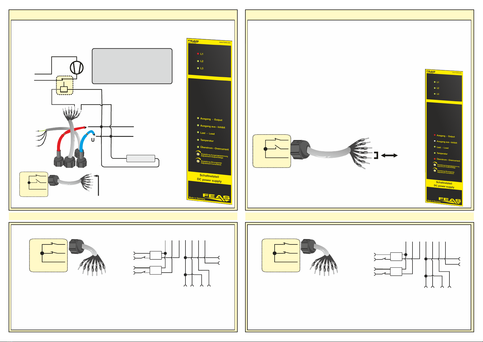
6. Meldekontakte und Kontaktbelegung 6. Signal contacts and pin assignment
1
1
4 45 6
7
4
3
2Phase
θunit>
interne Verdrahtung
internal wiring
Relais
Relay
1 2 3 4 5 6 7
1
1
4 45 6
7
4
3
2Phase
θunit>
interne Verdrahtung
internal wiring
Relais
Relay
1 2 3 4 5 6 7
Kontaktbelegungen:
4 : Signalmasse
5-4 : Standby-Modus + Reset-Funktion
5 offen : Normalbetrieb aktivieren
6-4 : FuseMode aktivieren
6 offen : Strombegrenzung aktivieren
7-4 : 0-10V Schnittstelle
(x-x : Steckbrücke/Gebrückt)
Relaisbelegungen (Öffner):
Pin-Nummer
1 : Relaismasse
1-2 : Bei Phasenausfall (L1, L2, L3), Überlast,
Kurzschluss, Notaus, Fusemode oder
Schlafmodus öffnet der Kontakt.
1-3 : Übertemperatur (θ>85°C)
Wenn Kerntemperatur größer als 75°C ist öffnet
der Kontakt. Das Gerät schaltet bei 85°C
selbstätig die Last ab.
Pin assignment:
4 : Signalground
5-4 : Standby-Modus + Reset-Function
5 open : Normal operation active
6-4 : FuseMode active
6 open : Current limiting active
7-4 : 0-10V Interface
(x-x : Jumper/Bridged)
Signal contacts (Opener):
Pin-Number
1 : Common relay contact
1-2 : At Phase loss (L1, L2, L3), overload,
short circuit, emergency stop, fuse mode or
standby the contact opens.
1-3 : Over-Temperature (θ>85°C)
When device-temperature is higher than 75 ° C
the contact opens.
The device switches the load off at 85 ° C.
Fusemode ist aktiviert und Strombegrenzung wird überschritten
Fusemode is activated and Current-limit is exceeded
Reset
interne Relais-Belegung
internal relays assignment
SNT150-K
1
2
3
Kontakte 4-5
contacts 4-5
Phasenausfall - Phase loss
Bei Phasenausfall zeigt das Gerät die fehlende
Phase mit einer roten LED an.
Für die Fernüberwachung öffnet Relaiskontakt 2.
In the case of a loss phase, the device indicate this
by a red LED.
For remote monitoring relay-contact 2 opens.
Uout
+
-Verbraucher
consumer
Lüfter
Fan
Relais
Relay
N
L1
interne Relais-Belegung
internal relays assignment
SNT150-K
1
2
3
Kontakt 2
contact 2
PE
L1
L2
L3
Wenn die elektronische Strombegrenzung
aktiviert ist (Fuse Mode), schaltet beim
Überschreiten der eingestellten Stromgrenze das
Gerät in Standby. Der Ausgang ist nun stromlos.
Dies geschieht auch beim Überschreiten der im
Diagramm (siehe Punkt 8) angegebenen
Überlastgrenze.
Bitte überprüfen Sie die angeschlossenen Systeme
auf Fehler.
Zum Neustart, ist das Gerät durch kurzzeitiges
Schließen der Kontakte 4-5 zurückzusetzen.
If the electronic current limitation is activated (fuse
mode), the device switches automatically to standby
when the set current limit is exceeded. The output is
now de-energized.
This also occurs if the overload limit shown in the
diagram (see point 8) is exceeded.
Please check the connected systems for errors.
In order to restart the device you have to reset it by
bridging contacts nr. 4-5 shortly.
Wird die elektronische Sicherung ausgelöst (bei
Fuse-Mode), blinken die LEDs Überstrom und
Ausgang rot.
(siehe auch LED-Anzeigen in Punkt 4)
Is the FuseMode triggered
the LEDs Overload and
Output are red flashing.
Der hier gezeigte Lüfter ist ein Vorschlag
zur Anwendung bei hohen Last- oder
Temperaturverhältnissen.
The fan shown here is a proposal for use
in high-load or temperature conditions.
SNT150-K
1
2
3
Das Überwachungsmanagement des SNT150-K erlaubt eine Vielzahl an Einstellmöglichkeiten am Gerät
und kann über zwei integrierte Relais-Kontakte fernüberwacht werden.
SNT150-K
1
2
3
The monitoring management of the SNT150-K allows a variety of settings on the device. It can be remotely
monitored via two built-in relay contacts.
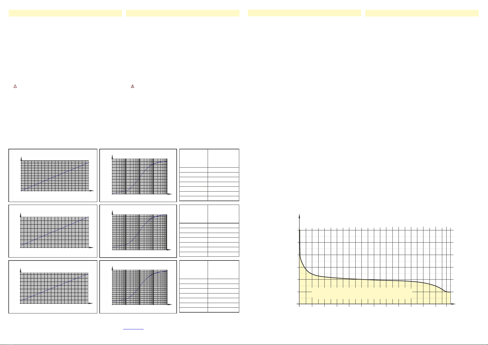
7. 0-10V Schnittstelle (Dimmer)
Die Ansteuerung der Schnittstelle erfolgt über ein
störungssicheres Gleichspannungssignal von 0V (min.
Ausgangsspannung 10,0V / 23,0 / 48,0V) bis 10V
(max. Ausgangsspannung 15,5V / 30,0V, / 60,0V).
Aufgrund der Eigenschaften dieser Schnittstelle
müssen folgende Punkte beachtet werden:
q Um die Schnittstelle zu verwenden ist das
eingebaute Potentiometer “Uadj” auf die höchste
Ausgangsspannung einzustellen.
q Die Steuerleistung wird vom Netzteil selbst erzeugt
(max. Strom 1mA pro Netzteil). Dies ermöglicht eine
einfache Verstellung der Ausgangsspannung mit nur
einem Widerstand an den Klemmen der Schnittstelle.
q Die Steuerleitung ist potentialgetrennt von der
Eingangsspannung, jedoch nicht von der
Ausgangsspannung des Netzteils.
q Ein angeschlossenes Steuergerät muss in der Lage
sein, den von den Netzteilen in die Steuerleitung
gelieferten Strom aufzunehemen (Stromsenke) und die
Steuerspannung zu verringern. Nicht alle Netzgeräte,
Wandlerkarten usw. haben diese Eigenschaften!
q Die Steuerleitung muss mit richtiger Polarität (+ / -)
angeschlossen werden.
7. 0-10V Interface (Dimmer)
The interface will be controlled by an interference proof
DC-Voltage from 0V (min. output voltage 10,0V / 23,0V
/ 48,0V) to 10V (max. output voltage 15,5V / 30,0V /
60,0V).
Because of the special attributes of this interface the
following issues should be observed:
q To operate the interface, the integrated
potentiometer “Uadj” has to be adjust to the maximum
output voltage.
q The power supply generates the control power by
itself (max. current 1mA each power supply). This
allows an adjustment of the output voltage by using a
resistor connected to the terminals of the interface.
q The control wire is potential separated from the
input voltage, but not from the output voltage.
q The connected controller has to be able to take the
control current of the power supplies (current sink) and
to lower the control voltage. Please notice that not all
power supplies, transformer cards etc. have these
features.
q The control wire has to be connected with the
correct polarity (+ / -).
10
10,5
11
11,5
12
12,5
13
13,5
14
14,5
15
15,5
16
0 0,5 1 1,5 2 2,5 3 3,5 4 4,5 5 5,5 6 6,5 7 7,5 8 8,5 9 9,5 10
Ua-Uc-Kennlinie / Characteristic curve
SNT15012-K
Ua / V
Steuerspannung / Control voltage
Ausgangsspannung
Output voltage
Uc / V
Kennlinien / Characteristic curves
22
23
24
25
26
27
28
29
30
0 0,5 1 1,5 2 2,5 3 3,5 4 4,5 5 5,5 6 6,5 7 7,5 8 8,5 9 9,5 10
Ua-Uc-Kennlinie / Characteristic curve
SNT15024-K
Ua / V
Steuerspannung / Control voltage
Ausgangsspannung
Output voltage
Uc / V
44
46
48
50
52
54
56
58
60
0 0,5 1 1,5 2 2,5 3 3,5 4 4,5 5 5,5 6 6,5 7 7,5 8 8,5 9 9,5 10
Ua-Uc-Kennlinie / Characteristic curve
SNT15048-K
Ua / V
Steuerspannung / Control voltage
Ausgangsspannung
Output voltage
Uc / V
1k0
3k32
10k0
20k0
100k0
475k0
1M0
Steuerwiderstand
nach E96-Reihe
.
Control resistor
acc. to E96-Series
Ausgangsspannung
SNT15012-K
.
Output voltage
SNT15012-K
10,22VDC
10,87VDC
12,10VDC
13,08VDC
14,82VDC
15,41VDC
15,50VDC
1k0
3k32
10k0
20k0
100k0
475k0
1M0
Steuerwiderstand
nach E96-Reihe
.
Control resistor
acc. to E96-Series
Ausgangsspannung
SNT15024-K
.
Output voltage
SNT15024-K
23,18VDC
24,04VDC
25,64VDC
26,92VDC
29,19VDC
29,97VDC
30,09VDC
1k0
3k32
10k0
20k0
100k0
475k0
Steuerwiderstand
nach E96-Reihe
.
Control resistor
acc. to E96-Series
Ausgangsspannung
SNT15048-K
.
Output voltage
SNT15048-K
48,15VDC
49,77VDC
52,80VDC
55,22VDC
59,50VDC
60,96VDC
10
10,5
11
11,5
12
12,5
13
13,5
14
14,5
15
15,5
16
0,1 1 10 100 1000
Ua-Rc-Kennlinie / Characteristic curve
SNT15012-K
Ua / V
Rc / kW
Steuerwiderstand / Control resistor
Ausgangsspannung
Output voltage
2 3 4 20 30 40 200 3000,2 0,3
22
22,5
23
23,5
24
24,5
25
25,5
26
26,5
27
27,5
28
28,5
29
29,5
30
0,1 1 10 100 1000
Ua / V
Ua-Rc-Kennlinie / Characteristic curve
SNT15024-K
Rc / kW
Steuerwiderstand / Control resistor
Ausgangsspannung
Output voltage
2 3 4 20 30 40 200 300
0,2 0,3
44
45
46
47
48
49
50
51
52
53
54
55
56
57
58
59
60
61
0,1 1 10 100 1000
Ua-Rc-Kennlinie / Characteristic curve
SNT15048-K
Ua / V
Rc / kW
Steuerwiderstand / Control resistor
Ausgangsspannung
Output voltage
2 3 4 20 30 40 200 300
0,2 0,3
Zur genaueren Bestimmung der Steuerspannung oder des Steuerwiderstandes laden sie sich
das Excel-Sheet, aus den Details des Netzteiles, auf www.feas.de herunter.
.
Please download the Excel-Sheet from the details of the power supply, on to get www.feas.de,
the exactly control voltage or control resistor.
Beispiele für die Ausgangsspannung gesteuert
durch einen, an der Schnittstelle angeschlossenen,
Widerstand.
Examples for the output voltage controlled by a
resistor, connected to the interface.
8. Strombegrenzung und Fusemode
Das SNT150-K kann über das 7-adrige graue
Steuerkabel (Pins 4 und 6) in zwei Betriebsarten
benutzt werden.
Strombegrenzung (Pin6 offen):
Über die Regelung des Potentiometers können Sie die
max. Stromstärke (0,5-1,5xI ) festlegen, an der das
nenn
Gerät die Last trennt und die Meldung über das Relais
erfolgt.
Dabei steht eine Leistung über 100% dem Anwender
nur für eine begrenzte Zeit zur Verfügung. Die Zeit ist
abhängig von der Höhe der (siehe Diagramm Leistung
unten). Nach Ablauf dieser Zeit trennt das Gerät für ca.
50 Sek. die Last und schaltet diese anschließend
wieder automatisch zu.
Zur Einstellung der Stromgrenze drehen Sie das
Potentiometer (Einstellung Stromgrenze) auf den
größtmöglichen Wert (im Urzeigersinn).
Stellen Sie die Last auf den Wert ein, an dem das
Netzteil die Last trennen soll.
Drehen Sie anschließend das Potentiometer zurück,
bis die Last getrennt wird.
Fuse-Mode (Pin4 und 6 gebrückt):
Durch eine Brücke zwischen Pin 4 und 6 wird die
elektronischen Sicherung (Fuse-Mode) aktiviert.
Die “Sicherung” löst aus:
wenn die von Ihnen eingestellte Strombegrenzung,
oder die zeitliche Begrenzung der Last (siehe
Diagramm) überschritten wird.
Bei Fuse-Mode schaltet das Gerät die Last sofort ab
und geht in Standby. Ein Neustart ist erst nach
manuellem Reset möglich.
8. Current-Limiting and Fusemode
The SNT150-K can be used in two different modes by
using the grey control cable (Pins 4 and 6) and the
potentiometer (Current limit).
Current limit (Pin6 open):
With the regulation of the potentiometer you can set up
the current (0.5-1.5xI ) on which the device limiter tilts
nom
and the message “overload” on relay 2 is displayed.
A performance more than 100% is only available for a
limited time. The time depends on the level (see
diagram below). After this time the device disconnects
the load for approx. 50 seconds and then switches it
on again automatically.
To set the current limit, turn the potentiometer
(Adjustment Current limit) to the highest possible
value (clockwise).
Set the load of your device to the value at which the
power supply should disconnect the load.
Then turn the potentiometer back until the load is
disconnected.
Fuse-Mode (Pin4 and 6 bridged)
A bridge between pins 4 and 6 activates the electronic
fuse (fuse mode).
The „fuse“ triggers:
if the current limit,
or the time limit of the load (see diagram) is exceeded.
In fuse mode, the device switches off the load
immediately and goes into standby. A restart is only
possible after a manual reset.
Überlastverhalten
Over-Load-characteristic
80%
100%
120%
140%
150%
Ausgangsstrom
Output Current
5 10 15 20 25
Zeit / Time (min.)
Betriebsbereich / Operation range
160%
180%
30
9. Allgemeine Sicherheitsvorschriften
Beim Umgang mit Produkten, die mit elektrischen Spannungen in
Berührung kommen, müssen die gültigen VDE / IEC / EN Vorschriften
beachtet werden. Besonders sei auf folgende Vorschriften hingewiesen:
VDE 0100, VDE 0550 / 0551, VDE 0711, VDE 0860, IEC 664, IEC 742, IEC
570, IEC 65
Bei Nichtbeachtung der Bedienungsanleitung oder der Anschlussvorschrift,
z.B. bei Vertauschen der Anschlussklemmen, kann das Gerät oder die
Anlage beschädigt werden und der Betreiber verliert seinen möglichen
Haftungsanspruch.
Durch den vollständigen Verguss darf das Gerät nicht geöffnet werden,
andernfalls erlöschen jeglicher Garantie- und Haftungsanpruch.
Werkzeuge dürfen an Geräten, Bauteilen oder Baugruppen nur benutzt
werden, wenn sichergestellt ist, dass die Geräte von der Versorgungs-
spannung getrennt sind und interne elektrische Bauteile entladen sind.
Vor dem Öffnen des Gerätes den Netzstecker ziehen und sicherstellen,
dass das Gerät spannungslos ist und bleibt. Bauteile, Baugruppen oder
Geräte dürfen nur in Betrieb genommen werden, wenn sie vorher in ein
berührungssicheres Gehäuse eingebaut wurden. Während des Einbaus
müssen sie stromlos sein.
Spannungsführende Kabel oder Leitungen, mit denen das Gerät, das
Bauteil oder die Baugruppe verbunden sind, müssen stets auf
Isolationsfehler oder Bruchstellen untersucht werden. Bei Feststellen eines
Fehlers in der Zuleitung muß das Gerät unverzüglich aus dem Verkehr
genommen werden, bis die defekte Leitungen ausgewechselt worden sind.
Der Anwender hat dafür Sorge zu tragen, dass die angegebenen
Gerätedaten nicht überschritten werden.
Wenn aus den vorgelegten Beschreibungen für den Anwender oder
Erwerber nicht eindeutig hervorgeht, welche Kennwerte für ein Gerät oder
Bauteil gelten, so muss stets ein Fachmann um Auskunft ersucht werden.
Im Übrigen unterliegt die Einhaltung von Bau- und Sicherheitsvorschriften
aller Art ( VDE, TÜV, Berufsgenossenschaften ) dem Anwender / Käufer.
9.General safety rules
When working with products which are in contact to dangerous electrical
voltages, attention must be payed to the relevant valid VDE / IEC / EN
regulations. Especialy with refrence to the following rules:
VDE 0100, VDE 0550 / 0551, VDE 0711, VDE 0860, IEC 664, IEC 742, IEC
570, IEC 65
In case of non-observance of this instructions the unit or other equipment
might be damaged and no warranty or liability could be accepted.
The device must not be opened as a result of complete potting, otherwise
all warranty and liability claims will lapse.
When it is necessary to use tools on the device components parts or
subassemblies make sure that the power is disconnected from the device
and all capacities are discharged.
Before opening the equipment disconnect the power cord and make sure
that the contacts are not energized. It is only allowed to take components
parts, subassemblies or device into operation if they are mounted in an
insulated housing. During the installation all devices have to be
disconnected from power sources.
Power cords and leads which are connected to the device, components or
subassemblies have to be inspected for damaged insulation. If a failure is
detected the device or the subassembly has to be put out of service at
once. It is not allowed to take the device or the subassembly into operation
before replacing the damaged power cord.
It is up to the user’s responsibility that the specification limits of the device
are not exeeded.
If the user is not fully able to relate the technical guidelines, a technical
adviser has to be asked for information.
The observance of construction requirements and safety rules (VDE, IEC,
employers liability insurenance i.e.) is subject to the user/customer.
148,0
230,0
54,0 34,0
54,054,0
34,0
133,2
7,4 7,4
GmbH
P.O. Box 1521
D - 22905 AHRENSBURG
Telefon: +494102 - 42082
Telefax: +494102 - 40930
www.feas.com
© 2019 ®
Suitable for M8 screws
All dimensions in millimeter
LDR30MH24
Mini DC-USV für die Hutschiene
Art.Nr.: 589960
Ÿ3 in 1, vereint Schaltnetzteil, Ladekontrolleinheit
und Akku in einem sehr kompakten Gehäuse
ŸPufferung eines Verbrauchers bei Netzausfall
ŸPufferzeit begrenzbar (1-20 Minuten und unbegrenzt)
ŸIm Pufferbetrieb manuell abschaltbar, “Schlafenlegen”
ŸIntegrierter NiMH Akkumulator mit 0,72 Ah (austauschbar)
ŸMikroprozessorgesteuerte Akkumulator-Überwachung und
Ladeanzeige
ŸLED-Anzeigen für Netzausfall, Übertemperatur, Überlast,
Akku laden, Akku Alarm, Pufferbetrieb
ŸRelais-Meldung von Netzausfall, Übertemperatur, Akku-
Defekt und Akkuspannung kritisch
Ÿ150% Überlast über längeren Zeitraum möglich
ŸKurzschlussfest, überlast- und leerlaufsicher
ŸAusgang potentialfrei nach VDE 0551
ŸSicherheit nach VDE, EN, UL und CSA
10. Maße Rückseite 10. Dimensions backside
Schutzart Gerät
IP 68, dazu sind die Potentiometer-Öffnungen nach
dem Einstellen zuverlässig abzudichten
Protective class
device
IP 68, if the pot-hole is reliably sealed after setting
up the device
device
e.g. SNT126
Grobschutz
Surge protective
devices
Typ1
>1300V
Mittelschutz
Surge protective
devices
Typ2
>600V
Feinschutz
Surge protective
devices
Typ3
<600V
Netzfilter
linefilter
optional
e.g. FEAS NFK
VDE0185-4 / EN62305-4
Blitz- und
Transientenschutz
lightning and over-
voltage protection
EMV Schutz
EMC protection
Für den ordnungsgemäßen Betrieb des
Gerätes ist ein Überspannungsschutz nach
VDE0185-4 / EN62305-4, und ein Netzfilter
vorzusehen.
For proper operation of the device provide an
overvoltage protection, according VDE0185-4 /
EN62305-4, and a line filter.
Aufgrund der internen Transienten-
Schutzschaltung darf die Isolationsprüfung
Ihrer Anlage nicht mit unserem Gerät erfolgen.
Due to the internal transient protection circuit,
the insulation test of your system must not be
carried out with our device.
IP65 - IP69K: Um Schutzklasse IP69K zu
erreichen, müssen die Poti-Öffnungen mit
einem 2-Komponenten-System zuverlässig
abgedichtet werden. Wenn dies nicht erfolgt,
liegt die Schutzklasse IP65 vor.
IP65 - IP69K: To achieve protection class
IP69K, the potentiometer openings must be
reliably sealed with a 2-component system. If
this is not done, the protection class is IP65.
This manual suits for next models
3
Other FEAS Power Supply manuals


