manuals.online logo
Brands
  1. Home
  2. •
  3. Brands
  4. •
  5. Federal Signal Corporation
  6. •
  7. Safety Equipment
  8. •
  9. Federal Signal Corporation StreetHawk User manual

Federal Signal Corporation StreetHawk User manual

2561765A
REV. A 1101
Printed in U.S.A.
INSTRUCTION SHEET
FOR
STREETHAWK® LED LOWER LEVEL RETROFIT KIT
SAFETY MESSAGETO INSTALLERS AND USERS
People’s lives depend on your safe installation of
our products. It is important to read, understand and
follow all instructions shipped with the products. In
addition, listed below are some other important
safety instructions and precautions you should
follow:
• To properly install this light, you must
have a good understanding of automotive
systems, along with proficiency in the
installation and use of safety warning
equipment.
• You should frequently inspect the light to
ensure that it is operating properly and
that it is securely attached to the vehicle.
• This product contains high intensity LED
devices. To prevent eye damage, DO NOT
stare into the light beam at close range.
• The light should be frequently inspected
to ensure that it is operating properly and
that it is securely attached to the vehicle.
• File these instructions in a safe place and
refer to them when maintaining and/or
reinstalling the product.
Failure to follow all safety precautions and
instructions may result in property damage, serious
injury, or death to you or others.
A. GENERAL.
WARNING
This unit is designed for use in the lower level
of the Streethawk lightbar only. Do not install
in any other lightbar.
This device is a retrofit LED light head for use in
the Federal Signal Streethawk lightbar. It is designed
to operate on a 12.8 VDC, negative ground system. It
is to be used with flashers designed for use with LED
lights, such as the Federal Signal Intelli-Flash™
Model 650200 Flasher or the Federal Signal FA3C
Flasher. The unit is comprised of an aluminum
mounting bracket with three LED modules installed,
a PCB board with heat sink attached, and a wire
harness.
B. KIT CONTENTS LIST .
Qty. Description Part No.
6 Cable Tie 150A109
2 Screw, Hex Hd., Type B 7011A122-08
1 Red female 1/4" tab connector 224A216-01
1 Red male 1/4" tab connector 224A217-01
1 Red #10 ring lug 224A200-05
C. INSTALLATION.
1. To install lower level LED modules when
using the Intelli-Flash Model 650200 flasher, proceed
as follows:
a. Remove the domes.
b. Move or remove any upper level lamp
assemblies that interfere with lower level lamp or
harness access. Rotate rotator worm gears by hand if
mechanism blocks screw access.
c. Service one lamp at a time to avoid
wiring mix-ups. Cut wire ties as needed for connector
access. Remove screws securing lamp to be replaced.
Trace leads back to harness connector and ground
screw and remove. Retain brass spacers and/or
washers for ground screw. Retighten the ground
screw after the old lamp ground connections to the
screw are removed.
d. Place the LED module into position
(electrical connector is at the top) and install the
screws. Take care not to strip the threads in the light
bar base.
e. Route leads to avoid interference, espe-
cially with hot or rotating parts. Plug the LED
module’s red power lead into the existing harness
connector. Make a note of the wire color. Route the
ground wire through the bar to the end where the
main cable enters the bar. Do not terminate at this
time.
f. Repeat for other lamp(s), and then
remove existing flashers and flasher harnesses.
g. Locate the Intelli-Flash flasher near the
terminal strip and secure.
h. To complete the wiring, follow the in-
structions supplied with the flasher.
i. After the flasher is installed and wired,
dress and tie leads.
j. Reinstall any previously removed hard-
ware, and then reinstall the domes.
2. To install lower level LED modules when
using the FA3C flasher, proceed as follows:
a. Remove the domes.
b. Move or remove any upper level lamp
assemblies that interfere with lower level lamp or
harness access. Rotate rotator worm gears by hand if
mechanism blocks screw access.
c. Service one lamp at a time to avoid
wiring mix-ups. Cut wire ties as needed for connector
access. Remove screws securing lamp to be replaced.
Trace leads back to harness connector and ground
screw and remove. Retain brass spacers and/or
washers for ground screw. Retighten the ground
screw after the old lamp ground connections to the
screw are removed.
d. Place the LED module into position
(electrical connector is at the top) and install the
screws. Take care not to strip the threads in the light
bar base.
e. Route leads to avoid interference, espe-
cially with hot or rotating parts. Plug the LED
module’s red power lead into the existing harness
connector. Cut and strip the ground lead to the
necessary length, crimp ring lug and slip over ground
screw. Tighten screw after all grounds to the screw
are in place.
f. Repeat for other lamps, then dress and tie
leads.
g. Replace existing flasher with FA3C
flasher and connect ground wire to chassis ground
screw. Secure flasher.
h. After the flasher is installed and wired,
dress and tie leads.
i. Reinstall any previously removed hard-
ware, and then reinstall domes.
D. TESTING.
WARNING
This product contains high output LED
devices. To prevent eye damage, do not stare
into the light beam at close range
After installation, check the entire system to be
sure the lights are flashing properly and all siren/
light system functions are operating properly.
SAFETY MESSAGETO OPERATORS
People’s lives depend on your safe use of our
products. Listed below are some important safety
instructions and precautions you should follow:
• Although your warning system is operat-
ing properly, it may not be completely
effective. People may not see or heed your
warning signal. You must recognize this
fact and continue driving cautiously.
• Also, situations may occur which obstruct
your warning signal when natural or
man-made objects are between your
vehicle and others, such as: raising your
hood or trunk lid. If these situations occur,
be especially careful.
• This product contains high intensity LED
devices. To prevent eye damage, DO NOT
stare into the light beam at close range.
• At the start of your shift, you should
ensure that the light is securely attached
and operating properly.
Failure to follow these safety precautions may
result in property damage, serious injury, or death to
you, to passengers, or to others.
RETAIN AND REFER TO THIS MESSAGE
E. MAINTENANCE.
WARNING
Crazing (cracking) of lenses will cause re-
duced effectiveness of the light. Do not use
cleaning agent (which will cause crazing) such
as strong detergents, solvents, or petroleum
products. If crazing of lenses does occur,
reliability of light for emergency signaling
purposes may be reduced until lenses are
replaced.
-2-
1. General.
Ordinary cleaning of the plastic lenses can be
accomplished by using mild soap and a soft rag.
Should fine scratches or a haze appear on a lens, they
can ordinarily be removed with a non-abrasive, high
quality, one-step, automotive paste cleaner/wax and
soft cloth.
2. PCB Assembly Replacement.
a. Remove the domes.
b. See figure 1. Disconnect the electrical
connector from the PCB assembly.
c. Gently pry the PCB assembly from the
snap-top standoffs on the backplane.
d. Remove the two heat sink retaining
screws and the heat sink.
e. Assembly is the reverse of disassembly.
Prior to installation of the PCB assembly, ensure that
the LED connector pins on the PCB are not bent or
damaged.
3. LED Module Replacement.
a. Remove the domes.
b. See figure 1. Disconnect the electrical
connector from the PCB assembly.
c. Gently pry the PCB assembly from the
snap-top standoffs on the backplane.
d. Remove the device from the light bar.
e. See figure 2. Remove and discard the
Rivscrews retaining the LED module to the
backplane. Remove the LED module.
f. Unlatch the Fresnel lens from the LED
module.
g. Snap the Fresnel lens onto the new
module. Make sure the rectangular recess in the lens
aligns with the black connector on the new LED
module.
h. Position the LED module on the
backplane, aligning the black connector on the LED
with the large clearance hole in the backplane.
Secure the module with the 2 6-32 screws provided.
i. Remainder is the reverse of disassembly.
4. Fresnel Lens Replacement.
Same as LED Module Replacement above,
except that the Rivscrews must be retained for reuse
if a new LED module is not being installed.
E. REPLACEMENT PARTS.
Description Part #
PCB Assembly Red/Amber Z2005175-N
PCB Assembly Blue Z2005175-02N
LED Module Assembly, Amber Z8625106-AS
LED Module Assembly, Blue Z8625106-BS
LED Module Assembly, Red Z8625106-RS
Lens, Fresnel 8625101
Manufactured by:
Federal Signal Corporation
Emergency Products Group
2645 Federal Signal Drive
University Park, Illinois 60466
Figure 1.
290A4361
PCB ASSEMBLY
HEAT SINK HEAT SINK
RETAINING SCREWS
BACKPLANE ASSEMBLY
ELECTRICAL
CONNECTOR
Figure 2.
290A4362
LED MODULE
FRESNEL LENS
BACKPLANE
ASSEMBLY
RIVSCREWS
-3-

Other Federal Signal Corporation Safety Equipment manuals

Federal Signal Corporation Allegiant Series Manual

Federal Signal Corporation

Federal Signal Corporation Allegiant Series Manual

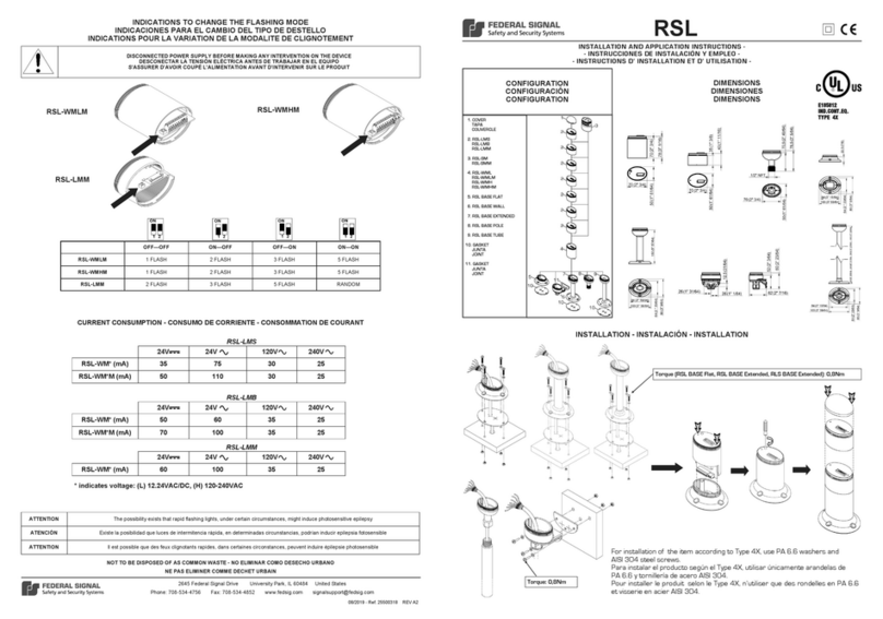
Federal Signal Corporation RSL-WMLM User guide

Federal Signal Corporation

Federal Signal Corporation RSL-WMLM User guide

Federal Signal Corporation GL2 User manual

Federal Signal Corporation

Federal Signal Corporation GL2 User manual

Federal Signal Corporation LEDTCL64 Quick guide

Federal Signal Corporation

Federal Signal Corporation LEDTCL64 Quick guide

Federal Signal Corporation VITALITE 121A User manual

Federal Signal Corporation

Federal Signal Corporation VITALITE 121A User manual

Federal Signal Corporation SmartSystem Load Management System Quick guide

Federal Signal Corporation

Federal Signal Corporation SmartSystem Load Management System Quick guide

Federal Signal Corporation SST3-MV User manual

Federal Signal Corporation

Federal Signal Corporation SST3-MV User manual

Federal Signal Corporation G-SND User manual

Federal Signal Corporation

Federal Signal Corporation G-SND User manual

Federal Signal Corporation QuadraFlare DOT Quick guide

Federal Signal Corporation

Federal Signal Corporation QuadraFlare DOT Quick guide

Federal Signal Corporation TCLF2 Assembly instructions

Federal Signal Corporation

Federal Signal Corporation TCLF2 Assembly instructions

Federal Signal Corporation GS2 User manual

Federal Signal Corporation

Federal Signal Corporation GS2 User manual

Federal Signal Corporation MicroPulse SignalMaster User manual

Federal Signal Corporation

Federal Signal Corporation MicroPulse SignalMaster User manual

Federal Signal Corporation SIGNALMASTER SMLED1-01 User manual

Federal Signal Corporation

Federal Signal Corporation SIGNALMASTER SMLED1-01 User manual

Popular Safety Equipment manuals by other brands

Petzl Am'D manual

Petzl

Petzl Am'D manual

DELTA PLUS FIDJI3 manual

DELTA PLUS

DELTA PLUS FIDJI3 manual

WaterWarden SAFETY COVER Installation & maintenance manual

WaterWarden

WaterWarden SAFETY COVER Installation & maintenance manual

CMC KOOTENAY ULTRA PULLEY manual

CMC

CMC KOOTENAY ULTRA PULLEY manual

Probuilder 18086 instruction manual

Probuilder

Probuilder 18086 instruction manual

IKEA BESKYDDA quick guide

IKEA

IKEA BESKYDDA quick guide

Petzl C086DA00 TECHNICAL NOTICE

Petzl

Petzl C086DA00 TECHNICAL NOTICE

Honeywell MILLER HandZup Instructions for use

Honeywell

Honeywell MILLER HandZup Instructions for use

SICK deTem4 LT Muting A/P operating instructions

SICK

SICK deTem4 LT Muting A/P operating instructions

Petzl Astro Bod Fast manual

Petzl

Petzl Astro Bod Fast manual

Restube Automatic instruction manual

Restube

Restube Automatic instruction manual

IOTA ETS20 DR Series instruction manual

IOTA

IOTA ETS20 DR Series instruction manual

Mobileye 8 Connect user manual

Mobileye

Mobileye 8 Connect user manual

Petzl charlet QUARK M U19 M quick start guide

Petzl

Petzl charlet QUARK M U19 M quick start guide

HOLOPHANE DM72N Series quick start guide

HOLOPHANE

HOLOPHANE DM72N Series quick start guide

Petzl ASAP'SORBER 20 manual

Petzl

Petzl ASAP'SORBER 20 manual

Capital Safety Tank Pod system Operator's manual

Capital Safety

Capital Safety Tank Pod system Operator's manual

Yoke N-623 User instruction

Yoke

Yoke N-623 User instruction

manuals.online logo
manuals.online logoBrands
  • About & Mission
  • Contact us
  • Privacy Policy
  • Terms and Conditions

Copyright 2025 Manuals.Online. All Rights Reserved.