manuals.online logo
Brands
  1. Home
  2. •
  3. Brands
  4. •
  5. Federal Signal Corporation
  6. •
  7. Safety Equipment
  8. •
  9. Federal Signal Corporation GS2 User manual

Federal Signal Corporation GS2 User manual

2561235B
REV. B 798
Printed in U.S.A.
INSTRUCTION SHEET
FOR
GRILLE LIGHT MODEL GS2
SAFETY MESSAGE TO INSTALLERS AND USERS
People’s lives depend on your safe installation of
our products. It is important to read, understand and
follow all instructions shipped with the products. In
addition, listed below are some other important
safety instructions and precautions you should
follow:
• To properly install this light: you must
have a good understanding of automotive
electrical procedures and systems, along
with proficiency in the installation and
use of safety warning equipment.
• DO NOT install equipment or route
wiring in the deployment path of an air
bag.
• When drilling into a vehicle structure, be
sure that both sides of the surface are
clear of anything that could be damaged.
• In order for the light to function properly,
a separate ground connection must be
made. If practical, it should be connected
to the negative battery terminal. At a
minimum, it may be attached to a solid
metal body or chassis part that will
provide an effective ground path as long
as the light system is to be used.
• Locate light control so the VEHICLE and
CONTROL can be operated safely under
all driving conditions.
• Do not attempt to activate or deactivate
light control while driving in a hazardous
situation.
• You should frequently inspect the light to
ensure that it is operating properly and
that it is securely attached to the vehicle.
• File these instructions in a safe place and
refer to them when maintaining and/or
reinstalling the product.
Failure to follow all safety precautions and
instructions may result in property damage, serious
injury, or death to you or others.
A. GENERAL.
The Model GS2 is a high intensity, wide angle,
directional strobe light head intended for use on a
vehicle’s exterior. It is designed for use with any of
Federal’s strobe power supplies (Models SPS2/SPS2P,
SPS4/SPS4J/SPS4P, and SPS6J). The unit is supplied
with an installed 4-foot cable and mounting brackets
for various mounting arrangements.
B. KIT CONTENTS LIST.
Qty. Description
1 Nut, Hex, 8mm, SS
1 Washer, Flat, 8mm, SS
1 Washer, Split, 8mm, SS
1 Screw, Hex Hd., 8 x 25mm
1 Connector, Plug
3 Terminals, Socket
1 Block, Pin
1 Nut, Plastic
1 Washer, Rubber
2 Bracket, Plastic
1 Screw, Allen Hd., 8 x 45mm
1 Nut, Stop, Hex, 8mm
6 Terminals, Socket (Red)
C. INSTALLATION.
WARNING
This product is intended for supplemental
warning and for use in conjunction with an
approved primary warning light system. This
strobe head can be powered by several types
of strobe power supplies. Consult local codes
and regulations to determine if the power
supply/strobe head combination complies.
NOTE
For maximum coverage and effectiveness, the
light assembly should be mounted in a
horizontal orientation.
1. Metal Bracket Mounting.
To install the unit using the installed metal
bracket, proceed as follows:
a. Determine the desired mounting location.
Scribe drill position marks on the mounting surface
for the 8mm mounting bolt and for a cable routing
hole (if desired).
CAUTION
Before drilling holes in ANY part of a vehicle,
be sure that both sides of the mounting
surface are clear of parts that could be dam-
aged; such as brake lines, fuel lines, electrical
wiring or other vital parts.
b. Drill a mounting hole and cable routing
hole (if desired) at the previously scribed drill posi-
tion marks.
c. Secure the light assembly to the mount-
ing surface using the bolt, washer, lockwasher, and
nut as shown in figure 1.
2. Plastic Bracket (Motorcycle) Mounting.
a. Remove the metal bracket from the light
assembly.
b. See figure 2. Attach the plastic brackets
to the light assembly using the 8mm allen head bolt
and the 8mm hex stop nut.
GRILLE LIGHT ASSEMBLY
WITH MOUNTING
BRACKET
POWER
SUPPLY
SCREW, ALLEN HEAD
8mm x 45mm
PLASTIC
BRACKETS
290A2793
MOUNTING
SURFACE
RUBBER WASHER
PIN BLOCK
HEX STOP
NUT, 8mm
PLASTIC NUT
NOTCH, 3/16" RADIUS
Figure 2.
c. Determine the desired mounting location.
Scribe a drill position mark on the mounting surface.
CAUTION
Before drilling holes in ANY part of a vehicle,
be sure that both sides of the mounting
surface are clear of parts that could be dam-
aged; such as brake lines, fuel lines, electrical
wiring or other vital parts.
d. Drill a 1-1/32" mounting hole at the
previously scribed drill position mark.
e. See figure 2. To prevent the light assem-
bly from rotating, the pin block can be installed. If
desired, position the light assembly on the mounting
surface and mark the center of the notch where the
pin block is located. File a 3/16" radius notch at the
marked location.
f. See figure 2. Secure the light assembly to
the mounting surface using the rubber washer, pin

block (if desired), and plastic nut.
-2-
GRILLE LIGHT ASSEMBLY
WITH MOUNTING
BRACKET
POWER
SUPPLY
290A2792
MOUNTING
SURFACE
LOCKWASHER,
8mm
FLAT WASHER,
8mm
HEX NUT,
8mm
CABLE HOLE
(IF DESIRED)
Figure 1.
D. ELECTRICAL CONNECTIONS.
CAUTION
The strobe light assembly is designed to be
used exclusively with Federal Signal’s Model
SPS2/SPS2P, SPS4/SPS4J/SPS4P, and SPS6J
power supplies. Use of any other power
supply may cause shortened service life of the
strobe tube.
The light assembly is supplied with an
unterminated 4-foot cable.
When a cable extension kit is used, refer to the
instructions packed with the cable extension kit
(Models SPC16 and SPC30) and the instructions
packed with the power supply.
See figure 3. If a cable extension kit is not used,
crimp the supplied pins on the end of the 4-foot cable.
Insert the pins in the supplied connector housing and
push until they snap into place. The connector can
now be plugged directly into the power supply.
Test the unit(s) for proper operation.
E. MAINTENANCE.
1. General.
WARNING
Crazing (cracking) of lenses will cause re-
duced effectiveness of the light. Do not use
cleaning agents (which will cause crazing)
such as strong detergents, solvents, or petro-
leum products. If crazing of lenses does occur,
reliability of light for emergency signalling
purposes may be reduced until lenses are
replaced.
Ordinary cleaning of the plastic lenses can be
accomplished by using mild soap and a soft rag.
Should fine scratches or a haze appear on a lens, they
can ordinarily be removed with a non-abrasive, high
quality, one-step, automotive paste cleaner/wax and a
soft cloth.
2. Strobe Tube Assembly Replacement.
WARNING
High voltages are present in a strobe light
system. Wait at least five (5) minutes, after
shutting off power, before servicing the unit.
Failure to do so may result in property
damage, serious injury, or death to you and
others.
a. Disconnect all power to the strobe system
power supply before performing any maintenance.
b. See figure 4. Remove and retain the four
screws which secure the lens. Carefully pull the lens
straight away from the grille light assembly.
c. Remove the screws that secure the strobe
tube assembly to the grille light’s plastic housing.
d. Disconnect the strobe tube assembly’s
connector from the cable.
e. Remove the screws that secure the
bracket to the strobe tube assembly. Install the
bracket on the new strobe tube assembly using the
previously removed screws.
CAUTION
Service life of strobe tube will be shortened if
glass is touched. If glass has been handled,
clean carefully with a grease solvent.
f. Connect the new strobe tube assembly’s
connector to the cable.
1 2 3
290A2741
STRIP
CRIMP
INSERT
CONNECT
DIRECTLY TO
POWER SUPPLY
RED
WHT
BLK
Figure 3.
-3-
290A2794
CONNECTOR
STROBE TUBE
ASSEMBLY
PLASTIC HOUSING
LENS, FLUTED
SCREWS (3)
SCREWS
(2)
SCREWS
(4)
BRACKET
Figure 4.
-4-
g. Install the new strobe tube assembly in
the plastic housing using the three previously re-
moved screws.
h. Replace the lens and secure with the
previously removed screws.
i. Reconnect all power connections to the
power supply and test for proper operation.
F. REPLACEMENT PARTS.
Description Part No.
Strobe Tube Assy. 8575067
Lens, Blue, Fluted 8575068
Lens, Red, Fluted 8575068-01
Lens, Amber, Fluted 8575068-02
Lens, Clear, Fluted 8575068-03
SAFETY MESSAGE TO OPERATORS
Peoples’ lives depend on your safe use of our
products.
Listed below are some important safety instruc-
tions and precautions you should follow:
• Although your warning system is operat-
ing properly, it may not be completely
effective. People may not see or heed your
warning signal. You must recognize this
fact and continue driving cautiously.
• Also, situations may occur which obstruct
your warning signal when natural or
man-made objects are between your
vehicle and others, such as: raising your
hood or trunk lid. If these situations
occur, be especially careful.
• At the start of your shift, you should
ensure that the light is securely attached
and operating properly.
Failure to follow these safety precautions may
result in property damage, serious injury, or death to
you, to passengers, or to others.
RETAIN AND REFER TO THIS MESSAGE

Other Federal Signal Corporation Safety Equipment manuals

Federal Signal Corporation TCLF2 Assembly instructions

Federal Signal Corporation

Federal Signal Corporation TCLF2 Assembly instructions

Federal Signal Corporation QuadraFlare DOT Quick guide

Federal Signal Corporation

Federal Signal Corporation QuadraFlare DOT Quick guide

Federal Signal Corporation SST3-MV User manual

Federal Signal Corporation

Federal Signal Corporation SST3-MV User manual

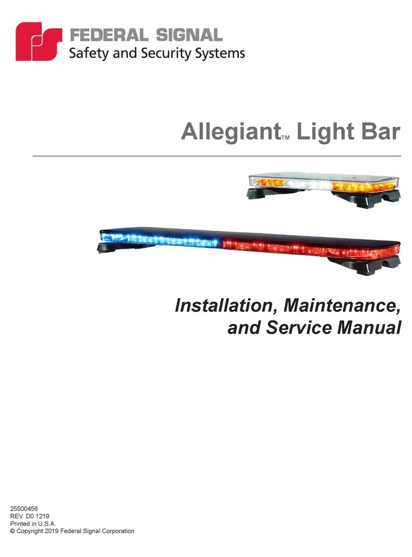
Federal Signal Corporation Allegiant Series Manual

Federal Signal Corporation

Federal Signal Corporation Allegiant Series Manual

Federal Signal Corporation MicroPulse SignalMaster User manual

Federal Signal Corporation

Federal Signal Corporation MicroPulse SignalMaster User manual

Federal Signal Corporation VITALITE 121A User manual

Federal Signal Corporation

Federal Signal Corporation VITALITE 121A User manual

Federal Signal Corporation LEDTCL64 Quick guide

Federal Signal Corporation

Federal Signal Corporation LEDTCL64 Quick guide

Federal Signal Corporation RSL-WMLM User guide

Federal Signal Corporation

Federal Signal Corporation RSL-WMLM User guide

Federal Signal Corporation G-SND User manual

Federal Signal Corporation

Federal Signal Corporation G-SND User manual

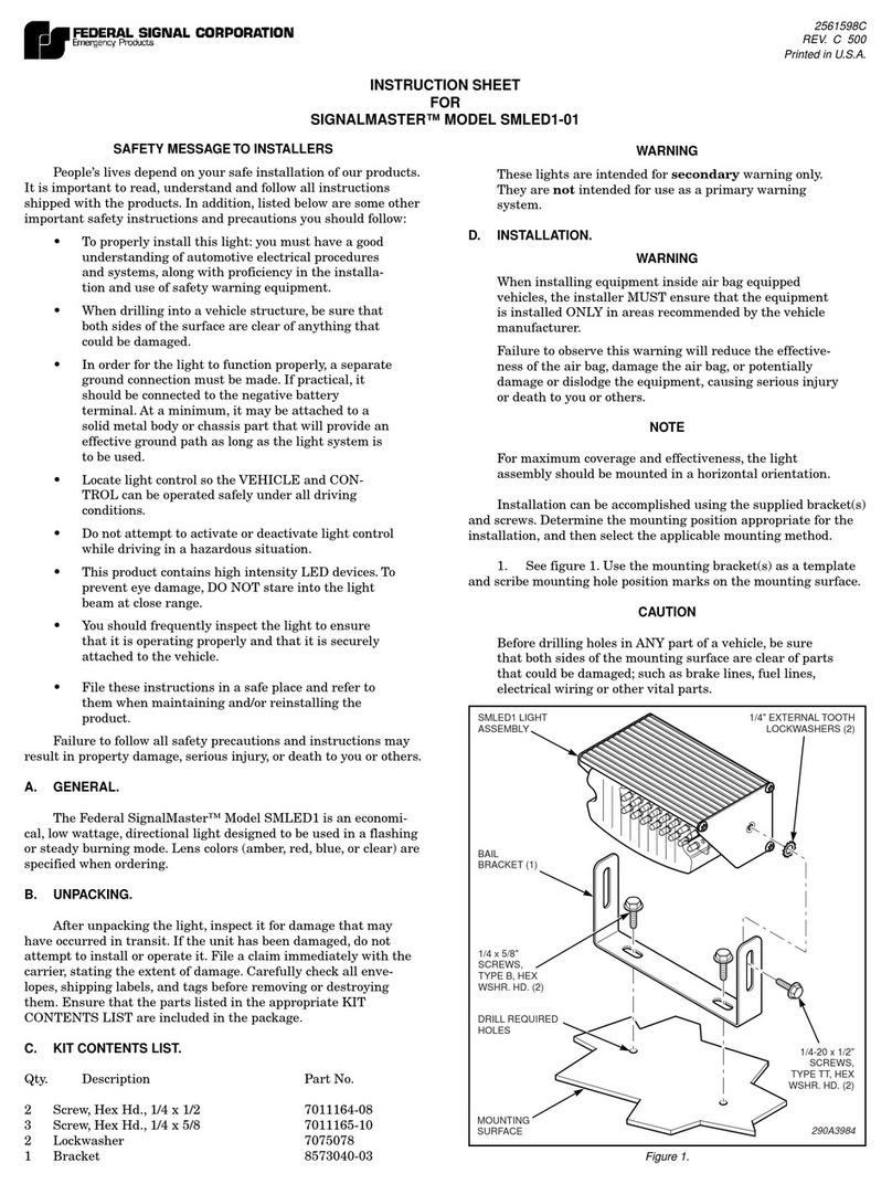
Federal Signal Corporation SIGNALMASTER SMLED1-01 User manual

Federal Signal Corporation

Federal Signal Corporation SIGNALMASTER SMLED1-01 User manual

Federal Signal Corporation GL2 User manual

Federal Signal Corporation

Federal Signal Corporation GL2 User manual

Federal Signal Corporation SmartSystem Load Management System Quick guide

Federal Signal Corporation

Federal Signal Corporation SmartSystem Load Management System Quick guide

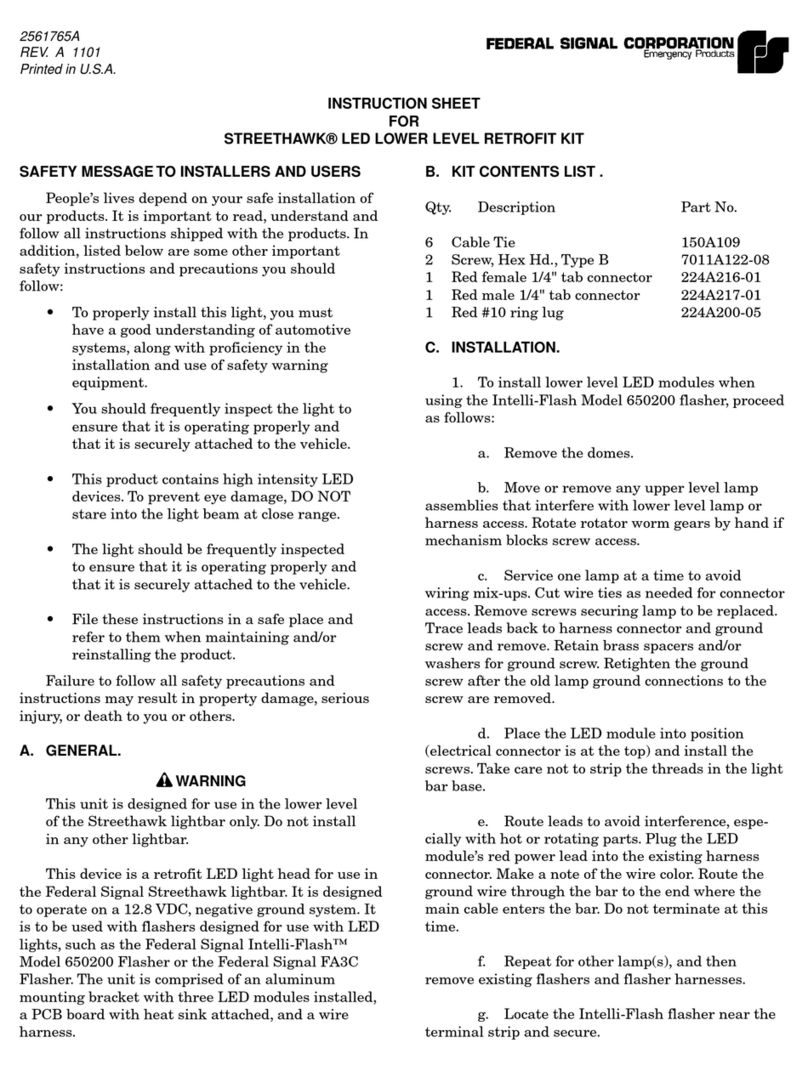
Federal Signal Corporation StreetHawk User manual

Federal Signal Corporation

Federal Signal Corporation StreetHawk User manual

Popular Safety Equipment manuals by other brands

MSA Gallet F2XR operating manual

MSA

MSA Gallet F2XR operating manual

KStrong AFX201001 User instruction manual

KStrong

KStrong AFX201001 User instruction manual

BRUNDLE MARANO EDGE SYSTEM installation instructions

BRUNDLE

BRUNDLE MARANO EDGE SYSTEM installation instructions

Banner EZ-SCREEN instruction manual

Banner

Banner EZ-SCREEN instruction manual

CARLO GAVAZZI SM instruction manual

CARLO GAVAZZI

CARLO GAVAZZI SM instruction manual

Protekt AT191 instruction manual

Protekt

Protekt AT191 instruction manual

Blue Sea Systems Sure Eject 7850 instructions

Blue Sea Systems

Blue Sea Systems Sure Eject 7850 instructions

EDELRID CABLE KIT LITE VI manual

EDELRID

EDELRID CABLE KIT LITE VI manual

Beghelli LC1-ECCO installation instructions

Beghelli

Beghelli LC1-ECCO installation instructions

Kong 911 NETFULL manual

Kong

Kong 911 NETFULL manual

Haws Delta 2203 instructions

Haws

Haws Delta 2203 instructions

Crye Precision LRB LEG LOOPS Operator's manual

Crye Precision

Crye Precision LRB LEG LOOPS Operator's manual

neofeu Pack&G'O manual

neofeu

neofeu Pack&G'O manual

Yale TIGRIP SHARK-S operating instructions

Yale

Yale TIGRIP SHARK-S operating instructions

Pizzato Elettrica CS AR-95V024 instruction sheet

Pizzato Elettrica

Pizzato Elettrica CS AR-95V024 instruction sheet

A.HABERKORN EN353-2 INSTRUCTIONS FOR USE AND TEST MANUAL

A.HABERKORN

A.HABERKORN EN353-2 INSTRUCTIONS FOR USE AND TEST MANUAL

Lakeland RM00457 user manual

Lakeland

Lakeland RM00457 user manual

U-Line S-12572 quick start guide

U-Line

U-Line S-12572 quick start guide

manuals.online logo
manuals.online logoBrands
  • About & Mission
  • Contact us
  • Privacy Policy
  • Terms and Conditions

Copyright 2025 Manuals.Online. All Rights Reserved.