Haug Multistat S User manual

Static Line
Operating instructions
Discharging power pac
k
Multistat S
Ident number: 01.7870.000, 01.7870.050, 01.7871.000,
01.7871.050, 01.7920.000 (UL), 01.7921.000 (UL)
Keep for future use!
GB


3
P
os: 2 /Bedienungsanleitungen/Inhaltsver zeichnis/Inhaltsverzeichni s@ 0\mod_1370516805648_ 2848.doc @ 3498 @ @ 1
Table of contents
=== Ende der Listefür Textmarke Inhalt1 ===
1Operator instructions ................................................. 4
1.1 Symbols used in operating instructions .............................4
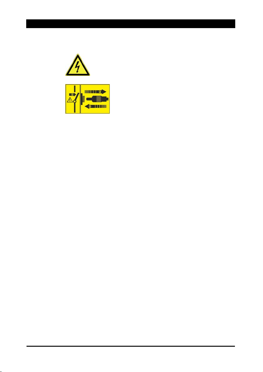
1.2 Symbols on the discharging power pack...........................5
2Safety........................................................................... 6
2.1 Intended use........................................................................7
3Product overview ........................................................ 8
4Install ........................................................................... 9
5Operate...................................................................... 14
5.1 Normal operation ..............................................................14
5.2 Normal operation and monitoring.....................................15
6Troubleshooting........................................................ 17
6.1 Replacing fuse...................................................................18
6.2 Flow chart..........................................................................19
7Accessories/spare parts .......................................... 20
8Technical data........................................................... 22
8.1 Characteristics and specification ......................................22
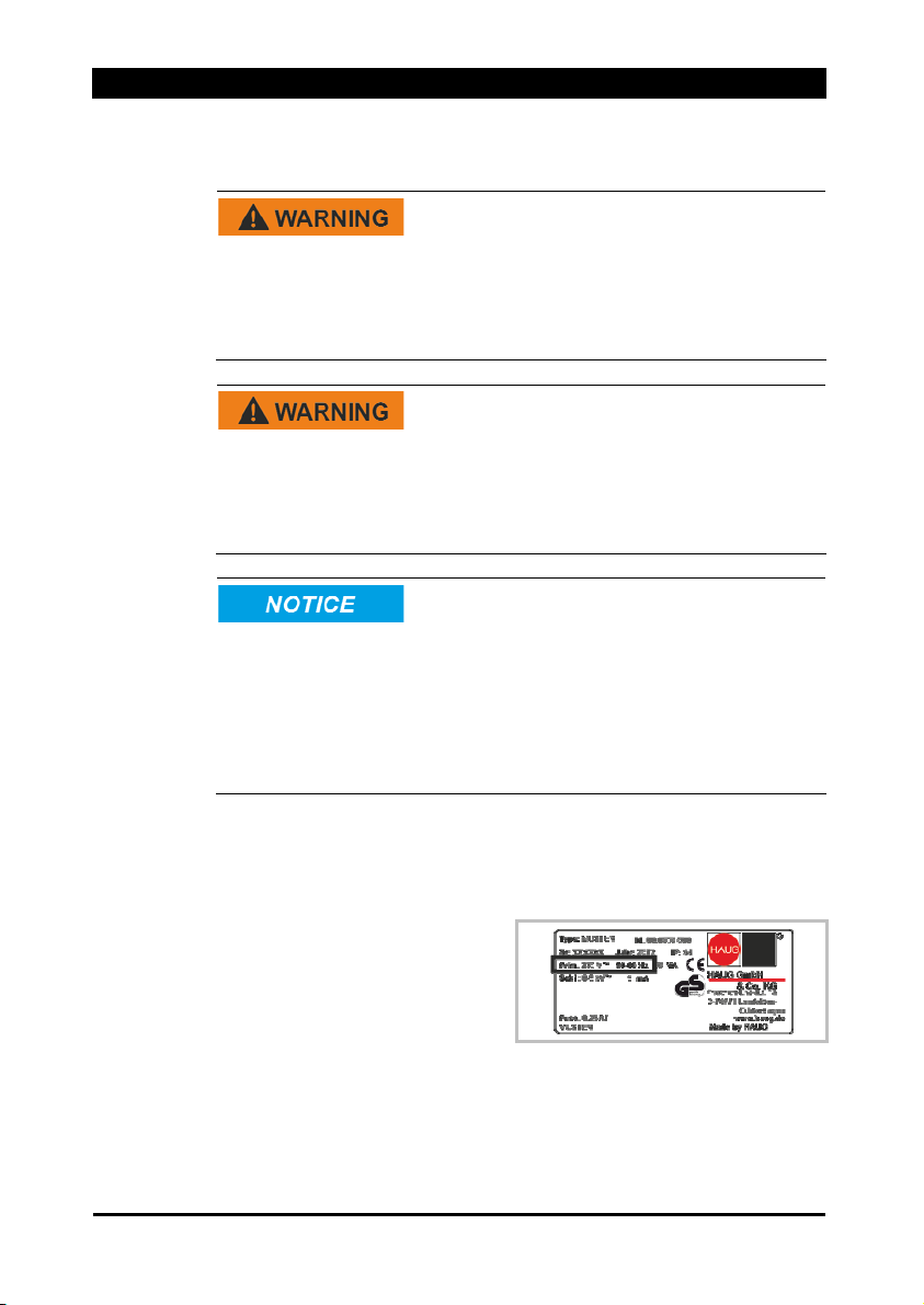
8.2 Supply voltage ..................................................................22
8.3 Ambient conditions ...........................................................23
8.4 Connected lengths............................................................24
8.5 Housing .............................................................................25
9Taking out of operation ............................................ 26
9.1 Storing ...............................................................................26
9.2 Disposing ..........................................................................26

1 Operator instructions
4
P
os: 4.1 /Bedi enungsanleitungen/Benu tzerhinweiseÜberschr ift Benutzerhin weise und E inleitung @ 0\mod_1342767330471_2848.doc @ 2863 @ 1 @ 1
1Operator instructions
Before installation and commissioning read these operating
instruction in full. Always observe the safety instructions.
These operating instruction is a part of the product; make sure you
retain them for later use or subsequent owners.
Pos: 4.2 /Bedienu ngsanleitungen/Benutzerhinwei se/Static Line/Ent ladenetzteileBenutzerhinwei s Entladenetzteil @ 0\mo d_1343294457468_2848.doc @ 2876 @ @ 1
The discharging power pack is maintenance free and operationally
safe when used as intended.
The term “high voltage” is abbreviated HV in these operating
instructions (e.g. HV terminal).
P
os: 4.3 /Bedienungsanleitungen/Benu tzerhinweise/Module Allgemein000 Symbo liki nder BA @ 0\mod_1343222128653_ 2848.doc @ 2871 @ 2 @ 1
1.1 Symbols used in operating instructions
Pos: 4.4 /Bedienu ngsanleitungen/Benutzerhin weise/Module Allgemein 002 Allg. Warnung @ 0\mod_1343033006879_2848.doc @ 2865 @ @ 1
Always observe this safety instruction to avoid critical or fatal injuries.
P
os: 4.5 /Bedienun gsanleitungen/Benutzerhinwei se/Module Allgemein004 A llg. Achtung @ 0\ mod_1343033837092_2848.doc @2867 @ @ 1
Always observe this safety instruction to avoid damage to property.
Pos: 4.6 /Bedienu ngsanleitungen/Benutzerhin weise/Module Allgemein 005 Allg. Hinweis @ 0\mod _1343034250933_2848.doc @2868 @ @ 1
NOTE:
Important notes and additional information.
Pos: 4.7 /Bedienu ngsanleitungen/Benutzerhin weise/Module Allgemein 006 Allg. Nicht Hau smüll werfen @ 0\m od_1343034423725_2848.doc @ 2869 @ @ 1
Never dispose of with household garbage.
P
os: 4.8 /Bedienungsanlei tungen/Seitenumbruch @ 0\mo d_1343041632941_0.doc @ 2959 @ @ 1

1 Operator instructions
5
os: 4.9 /Bedienun gsanleitungen/Benutzerhinwei se/Static Line/En tladenetzteileSymbolik aufEntladen etzteil @ 0\mod_1343288892383_ 2848.doc @ 2872 @ 2 @ 1P
1.2 Symbols on the discharging power pack
P
os: 4.10 /Bedienungsanleitungen/Benu tzerhinweise/Module AllgemeinWarnun gh ohe el. Spannung @0\ mod_1343220457214_2848.doc @ 2870 @ @ 1
WARNING!
High voltage
P
os: 4.11 /Bedienun gsanleitungen/Benutzerhinweise/M odule AllgemeinAchtung ein-/ausstecken - Entladenetzteil @ 0\mod_1343289707217_2848.doc @ 2873 @ @1
ATTENTION!
Only plug in/unplug the ionizing unit at the HV
terminal when the discharging power pack is
switched off.
Pos: 4.12 /Bedienungsanleitun gen/Seitenumbruch @ 0\mod_1343041632941_0.doc @ 2959 @ @ 1

2 Safety
6
os: 5.1 /Bedienun gsanleitungen/Sicherheit /Module001 Überschrift S icherheit und Einleitun g @ 0\mod_1343301080295_2848. doc @ 2877 @ 1 @ 1P
2Safety
Only the persons authorized by the operator may carry out tasks on
the discharging power pack.
The installer must be a trained and qualified electrician and read the
operating instructions in full.
The operator must read the operating instructions in full.
When working on the discharging power pack, switch off the voltage
supply and secure against inadvertent switching on.
P
os: 5.2 /Bedienungsanleitungen/S icherheit/Module002 Sicherheitsk apitel Manipulation @ 0\mod_1343307195004_2848.doc @ 2878 @ @ 1
Hazards caused by manipulated or faulty discharging power
pack
Unauthorized modifications, moisture or damage to the discharging
power pack may result in electric shocks or fire hazards due to
sparking.
• For reasons of safety, never open or modify the discharging
power pack.
• In the event of visible damage or suspected electrical defects,
take the discharging power pack out of operation immediately
and secure against inadvertent reuse.
• Protect the discharging power pack from moisture.
• Never carry out any unauthorized repairs to the discharging
power pack.
• Always switch off the discharging power pack after use.
• Do not keep any inflammable materials in the vicinity of the
discharging power pack or its components.
Pos: 5.3 /Bedienun gsanleitungen/Seitenumbruch @ 0\mod_1343041632941_0.doc @ 2959 @ @ 1

2 Safety
7
os: 5.4 /Bedienungsanleitungen/Sich erheit/ModuleBest. Verw. Entladenetzteil @ 0\mod_1348487358998_2848. doc @ 2882@ 2 @ 1P
2.1 Intended use
Risk of explosion!
The discharging power pack may generate sparks which ignite
gases, dust or similar substances.
• Never install or use the discharging power pack in areas with
potentially explosive atmospheres.
The discharging power pack is intended exclusively for the supply of
alternating high voltage to HAUG ionizing units with X-2000
connector. In combination with an ionizing unit, electrostatic charges
are neutralized in a production process.
Always observe the installation and operating conditions indicated in
these operating instructions.
Warranty only covers products, accessories or spare parts of HAUG
GmbH & Co. KG.
P
os: 5.5 /Bedienungsanlei tungen/Seitenumbruch @ 0\mo d_1343041632941_0.doc @ 2959 @ @ 1

3 Product overview
8
os: 6.1 /Bedienungsanlei tungen/Geräteübersicht/Über schrift Geräteübersicht @ 0\mod_1350993675349_2848.doc @ 2918 @ 1 @ 1P
3Product overview
P
os: 6.2 /Bedienungsanleitun gen/Geräteübersicht/Entladenet zteile/Module Multistat S/001 G eräteübersicht Multistat S @ 0\m od_1350993787427_2848.doc @ 2919 @ @ 1
Multistat S
AFuse holder with fuse
(Replacing fuse, refer page
18)
B Error indicator lamp (flashes
yellow in the event of a
defect)
C Mains switch (lights up
green when discharging
power pack is switched on)
Pos: 6.3 /Bedienungsanlei tungen/Geräteübersicht/Entl adenetzteile/Module Multistat S/002 Geräteübersicht Multistat S @ 0\mod_1350994056036_2848. doc @ 2920 @ @1
D K1 signalling socket
(monitoring)
E K6 signalling socket
(external reset)
F Mains supply
G 4 x HV terminal
H Ground connection
(terminal)
I Bracket
P
os: 6.4 /Bedienungsanleitun gen/Geräteübersicht/Entladenet zteile/Module Multistat S/003 G eräteübersicht Multistat S @ 0\m od_1350994141536_2848.doc @ 2921 @ @ 1
J HV display
P
os: 6.5 /Bedienungsanlei tungen/Seitenumbruch @ 0\mo d_1343041632941_0.doc @ 2959 @ @ 1

4 Install
9
os: 7.1 /Bedienungsanleitungen/In stallieren/Entladenetzteile/ Module Allgemein/001 Überschrift und Einleitung Install ation @0\ mod_1348563594309_2848.doc @ 2883 @1 @ 1P
4Install
Risk of explosion!
The discharging power pack may generate sparks which ignite
gases, dust or similar substances.
• Never install or use the discharging power pack in areas with
potentially explosive atmospheres.
Electric shock hazard!
An electric shock hazard results from a faulty connection of the
discharging power pack to the power supply.
• The discharging power pack must only be installed by a trained
and qualified electrician.
Damage to equipment!
Continuous overloading of the discharging power pack may result in
failures.
• Never exceed the permissible connected length.
• Never install the discharging power pack on a surface generating
or radiating heat.
• Never install at a location subject to direct solar irradiation.
P
os: 7.2 /Bedienungsanleitungen/In stallieren/Entladenetzteil e/Module Allgemein/002 Bestelldaten überprüfen @ 0\mod_ 1348644282961_2848.doc @ 2884 @ @ 1
1. Check the model plate of the discharging power pack against the
ordering data. In the event of damage to the discharging power
pack, contact HAUG GmbH & Co. KG.
P
os: 7.3 /Bedienun gsanleitungen/Installier en/Entladenetzteile/Module Multistat S/003 Typenschild @ 0\mo d_1348644750003_2848.doc @ 2885 @ @ 1
2. Before connecting, make
sure that the correct supply
voltage is available for the
discharging power pack.
• The model plate
attached to the housing
indicates the voltage.
• If the supply voltage is incorrect, the discharging power pack
may be damaged.
P
os: 7.4 /Bedienungsanlei tungen/Seitenumbruch @ 0\mo d_1343041632941_0.doc @ 2959 @ @ 1

4 Install
10
os: 7.5 /Bedienungsanleitungen/In stallieren/Entladenetzteil e/Module Multistat S/004 Befestigen @ 0\mod_1349866526992_2848. doc @2886 @ @ 1P
3. Place the discharging
power pack at the desired
location and attach with the
enclosed retaining plate, if
appropriate.
• The operation of the
discharging power pack
is not affected by the
position in which it is
installed.
• We recommend
installing the
discharging power pack
with the HV terminals
pointing downwards (to
protect them from
moisture, oil and dirt).
P
os: 7.6 /Bedienun gsanleitungen/Installier en/Entladenetzteile/Module Multistat S/005 Sicherstellen-AU S @ 0\mod_1349867779648_2848.do c @ 2887 @ @ 1
4. Ensure that the discharging
power pack is switched off.
P
os: 7.7 /Bedienun gsanleitungen/Installier en/Entladenetzteile/Module Multistat S/006 Erden @ 0\mod_1349875499921_ 2848.doc @ 2888 @ @ 1
5. The ground socket of the
discharging power pack
must be connected to
ground potential in line with
applicable standards.
• Grounding cables of at
least 1,5 mm2must be
used.
P
os: 7.8 /Bedienungsanlei tungen/Seitenumbruch @ 0\mo d_1343041632941_0.doc @ 2959 @ @ 1

4 Install
11
os: 7.9 /Bedienun gsanleitungen/Installier en/Entladenetzteile/Module Multistat S/007 Anschließen @ 0\ mod_1349936519694_2848.doc @ 2889@ @ 1P
6. Connect the discharging
power pack to the supply
voltage. Always connect the
protective earth conductor
(green-yellow) with a
functioning protective earth
of the mains.
• Connecting the PE
conductor via parts of a
machine body is
insufficient.
• L = brown conductor
• N = blue conductor
• PE = green/yellow
conductor
P
os: 7.10 /Bedienungsanleitungen/In stallieren/Entladenetzteil e/Module Allgemein/008 Achtung EIN-AUS-Steck en@ 0\mod_13499407133 11_2848.doc @ 2890 @ @1
Contact and separation spark-overs!
When the ionizing unit is plugged in or unplugged while the
discharging power pack is switched on, spark-overs will occur at the
HV connection. This may result in defects in the discharging power
pack.
• Switch off discharging power pack before plugging in/unplugging
ionizing unit.
P
os: 7.11 /Bedienungsanleitungen/In stallieren/Entladenetzteil e/Module Allgemein009 Ionisationsgerät anschl ießen @ 0\mod_1349946705235_2848.doc @ 2891 @ @ 1
7. Connect the ionizing unit to
the HV terminal of the
discharging power pack.
• Insert the ionizing unit’s
HV plug in the HV
terminal of the
discharging power pack
and press the HV cable
until it reaches the stop.
• Screw the screw cap
onto the HV terminal and tighten by hand.
P
os: 7.12 /Bedienungsanleitungen/In stallieren/Entladenetzteil e/Module Allgemein/010 HINWEIS HS-Anschluss @ 0\mod_1370522861821 _2848.doc @ 3505 @ @ 1
NOTE:
Also note the maximum connected length.
Protect unused HV terminals against the ingress of environmental
substances using the red blind plugs.
P
os: 7.13 /Bedienungsanleitung en/Seitenumbruch @ 0\mod_1343041632941_0.doc @ 2959 @ @ 1

4 Install
12
os: 7.14 /Bedienun gsanleitungen/Installier en/Entladenetzteile/ Module Multistat S /011 Anschluss K6 S ignalbuchse @ 0\mod_1349954799171_ 2848.doc @ 2893 @ @ 1P
8. If required, the signalling
line K6 can be connected to
the K6 signalling socket (E).
• The K6 signalling socket
allows the discharging
power pack to be reset
externally.
Configuration of K6 signalling
socket:
A External reset (potential-free
normally open contact)
NOTE:
The discharging power pack can be reset by actuating the external
reset button or switching the unit off/on (mains switch or mains
voltage).
P
os: 7.15 /Bedienungsanleitung en/Seitenumbruch @ 0\mod_1343041632941_0.doc @ 2959 @ @ 1

4 Install
13
os: 7.16 /Bedienun gsanleitungen/Installier en/Entladenetzteile/ Module Multistat S /012 Anschluss K1 S ignalbuchse @ 0\mod_1349956193945_ 2848.doc @ 2894 @ @ 1P
9. If required, the signalling
line K1 can be connected to
the K1 signalling socket (D).
• The K1 signalling socket
can be used to monitor
the correct function of
the discharging power
pack.
• Relay contact rating:
max. 24 V~ / 35 V=,
max. 50 mA
Configuration of K1 signalling
socket:
A Relay contact mains failure
B Relay contact operational
failure
Switching status table for K1 signalling socket
Operating conditions Contacts closed
Normal
operation
Mains voltage
present
HV present 1 and 3 5 and 6
Internal
fault
Mains voltage
present
HV failure 1 and 3 4 and 6
External
fault
Mains failure Not defined 1 and 2 5 and 6
More information in chapter "Normal operation and monitoring" on
page 15.
P
os: 7.17 /Bedienungsanleitungen/In stallieren/Entladenetzteil e/Module Allgemein/013 Betriebsbereit @ 0\mod_1349958954146_ 2848.doc @ 2895 @ @ 1
10. The discharging power pack is ready for operation.
P
os: 7.18 /Bedienungsanleitung en/Seitenumbruch @ 0\mod_1343041632941_0.doc @ 2959 @ @ 1

5 Operate
14
os: 8.1 /Bedienung sanleitungen/Betreiben/Entladen etzteile/Module Allg emein/001 Überschrift Betrei ben und Einleitun g @ 0\mod_1349959385481_2848.d oc @ 2896 @ 1 @ 1P
5Operate
Preconditions:
The discharging power pack and the ionizing unit are connected and
installed as specified in the operator instructions.
P
os: 8.2 /Bedienungsanlei tungen/Betreiben/Entladenet zteile/Module Multistat S /002 Hinweis @ 0\mod_1350380568099_ 2848.doc @ 2897 @ @ 1
NOTE:
After a fault, the error indicator lamp will start to flash with a delay of
10 seconds. The discharging power pack switches off the high
voltage.
This can be triggered by:
• a drop of the high voltage at the HV output to below 4.2 kV~.
• a sparkover in the ionization system.
• a short circuit in the ionization system.
The discharging power pack can be reset by triggering the external
reset or switching off/on (mains switch or mains voltage). If the
defect persists, refer to the following chapter “Troubleshooting”.
Refer page 17.
P
os: 8.3 /Bedienun gsanleitungen/Betreiben/Entlad enetzteile/Module Mu ltistat S/003 Norm al betreiben @ 0\mod_ 1350384785057_2848.doc @ 2898 @ 2 @ 1
5.1 Normal operation
Optionally, the signalling line K6 (accessory) can be connected to
the K6 signalling socket (E). This allows an external reset to be
carried out.
1. Switch on the discharging power pack using the mains switch
(C).
• The mains switch will illuminate green to confirm.
• The HV output voltage is indicated at the HV display (J) of the
discharging power pack.
• The discharging power pack is in operating mode.
P
os: 8.4 /Bedienun gsanleitungen/Betreiben/Entlad enetzteile/Module Mu ltistat S/Hinweis F ehlerlampe @ 0\mod_1360154588462_2848. doc @ 2949 @ @ 1
NOTE:
The flashing of the error indicator lamp indicates a defect. The
discharging power pack can be reset by triggering the external reset
or switching off/on (mains switch or mains voltage). If the defect
persists, refer to the following chapter “Troubleshooting”. Refer
page 17.
P
os: 8.5 /Bedienungsanlei tungen/Seitenumbruch @ 0\mo d_1343041632941_0.doc @ 2959 @ @ 1

5 Operate
15
os: 8.6 /Bedienun gsanleitungen/Betreiben/Entlade netzteile/Module Mu ltistat S/004 Norm al betreiben und über wachen @ 0\mod_1350385577041_2848.do c @ 2899 @ 2 @ 1P
5.2 Normal operation and monitoring
To enable monitoring, connect the signalling line K1 (accessory) to
the signalling socket K1 (D).
1. Switch on the discharging power pack using the mains switch
(C).
• The mains switch will illuminate green to confirm.
• The HV output voltage is indicated at the HV display (J) of the
discharging power pack.
• The discharging power pack is in operating mode.
The function of the discharging power pack can be evaluated by
means of the connected signalling line K1.
P
os: 8.7 /Bedienun gsanleitungen/Betreiben/Entlad enetzteile/Module Mu ltistat S/Hinweis F ehlerlampe @ 0\mod_1360154588462_2848. doc @ 2949 @ @ 1
NOTE:
The flashing of the error indicator lamp indicates a defect. The
discharging power pack can be reset by triggering the external reset
or switching off/on (mains switch or mains voltage). If the defect
persists, refer to the following chapter “Troubleshooting”. Refer
page 17.
Pos: 8.8
/Bedienungsanleitungen/Bet reiben/Entladenetzteile/ Module Multistat S/ 005 Anwendungsbeispiele @ 0\mo d_1350389535939_2848.doc @ 2902 @ @ 1
Application examples (e.g. connection to PLC)
P
os: 8.9 /Bedienun gsanleitungen/Betreiben/Entlad enetzteile/Module Mu ltistat S/006 Anwen dungsbeispiel 1 @ 0\mo d_1350387068869_2848.doc @2900 @ @ 1
Example 1:
A Relay contact for mains
failure
B Relay contact for HV failure
C1 Bridge 1
C2 Bridge 2
D Output
E Input
High-voltage Continuity (D and E)
Normal operation no
Malfunction yes
P
os: 8.10 /Bedienungsanleitung en/Seitenumbruch @ 0\mod_1343041632941_0.doc @ 2959 @ @ 1

5 Operate
16
os: 8.11 /Bedienungsanleitungen/Bet reiben/Entladenetzteile/Modul e Multistat S/007 Anwendungsbeispiel 2 @ 0\mod_1350389301705_ 2848.doc @ 2901 @ @ 1P
Example 2:
A Relay contact for mains
failure
B Relay contact for HV failure
C Bridge
D Output
E Input
High-voltage Continuity (D and E)
Normal operation yes
Malfunction no
P
os: 8.12 /Bedienungsanleitung en/Seitenumbruch @ 0\mod_1343041632941_0.doc @ 2959 @ @ 1

6 Troubleshooting
17
os: 9.1 /Bedienungsanleitun gen/Fehler beheben/Entladenetztei le/Module Allgemein/001 Fehler beheb en Einleitung @ 0\mod_1350390750986_2848.doc @ 2903 @ 1 @ 1P
6Troubleshooting
Electric shock hazard!
The discharging power pack is operated electrically and generates a
high electric voltage. In the event of any faults, there is a risk of an
electric shock.
• Faults must only be eliminated by a trained and qualified
electrician.
NOTE:
If the error cannot be removed in this way, return the discharging
power pack and ionizing unit for checking to HAUG GmbH & Co. KG
(for address, see reverse).
Pos: 9.2 /Bedienun gsanleitungen/Fehler beh eben/Entladenetzteile/ Module Multistat S/ 002 Tabelle Fehler beheben @0\mod_1350632585 811_2848.doc @ 2904 @ @1
Error Cause Measure for removing fault
Mains failure Check mains fuse
Check fuse in discharging
power pack.
Check connections in
discharging power pack.
No
ionization No HV
Check HV output of
discharging power pack
using the Combicheck
(Accessories/spare parts,
refer page 20).
Discharging power
pack is damaged
Shut the discharging power
pack down immediately and
secure against switching on.
Ionizing unit is dirty Clean ionizing unit
Short circuit Perform work steps
according to the following
flow chart. Refer page 19.
Error
indicator
lamp
flashes
Sparkover Perform reset
P
os: 9.3 /Bedienungsanlei tungen/Seitenumbruch @ 0\mo d_1343041632941_0.doc @ 2959 @ @ 1

6 Troubleshooting
18
os: 9.4 /Bedienung sanleitungen/Fehler beheben /Entladenetzteile/Module A llgemein/003 Sicherung austauschenEinl eitung @ 0\mod_1350633739655_ 2848.doc @ 2905 @ 2@ 1P
6.1 Replacing fuse
Damage to equipment!
An incorrect fuse in the discharging power pack may cause a defect.
This may result in a cable fire.
• Only use fuses of the type indicated.
• Do not use repaired fuses.
• Do not bridge the fuse.
The unit type and the rated voltage are indicated on the nameplate.
P
os: 9.5 /Bedienung sanleitungen/Fehler beheben /Entladenetzteile/Modul e Multistat S/004 Ar beitsschritte Sicherun gsaustausch @ 0\mod_1350634341655_2848. doc @ 2906 @ @1
1. Disconnect discharging
power pack from supply.
2. Determine and remove the
cause for the blown fuse.
3. Detach the fuse holder (A)
using a screwdriver and lift
out.
4. Replace fuse and reattach
fuse holder.
Use the following fuse only:
• 100 / 115 V = 0,50 A slow, 5 x 20 mm
• 200 / 230 V = 0,25 A slow, 5 x 20 mm
Pos: 9.6 /Bedienun gsanleitungen/Seitenumbruch @ 0\mod_1343041632941_0.doc @ 2959 @ @ 1

6 Troubleshooting
19
os: 9.7 /Bedienun gsanleitungen/Fehler beheb en/Entladenetzteile/Modu le Multistat S/005 F lussdiagramm @ 0\mod_1350636719405_ 2848.doc @ 2907@ 2 @ 1P
6.2 Flow chart
The error indicator lamp flashes.
Discharging power
pack is fault
y
Switch off discharging power pack and
unplug ionizing units.
Disconnect signalling line K1/K6 from
the discharging power pack.
Switch on the discharging power pack.
yes
Switch off discharging power pack and
connecting a ionizing unit.
Switch on the discharging power pack.
This ionizing unit
has a fault.
(Short circuit)
Ionizing system is ok
no
no
no
yes
yes
This ionizing unit
has a fault.
(Short circuit)
Switch off discharging power pack and
connecting another ionizing unit.
Switch on the discharging power pack
etc.
Flashes the error
indicator lamp?
Flashes the error
indicator lamp?
Flashes the error
indicator lamp?
P
os: 9.8 /Bedienungsanlei tungen/Seitenumbruch @ 0\mo d_1343041632941_0.doc @ 2959 @ @ 1

7 Accessories/spare parts
20
os: 10.1 /Bedienungsanleitungen/Zu behör, Ersatzteile/Module Allgemein/001 Üb erschrift Zubehör-Ersatzteile @ 0\mod_1350984310358 _2848.doc @ 2915@ 1 @ 1P
7Accessories/spare parts
Accessories and spare parts can be sourced from your authorized
sales partner or directly from HAUG GmbH & Co. KG (for address,
refer to back cover).
P
os: 10.2 /Bedienungsanleitungen/Zu behör, Ersatzteile/Entladenetzteile/ Module Multistat S/002 Zubehör Signalleitung K1 @ 0\mod_1350984429951_2848. doc @ 2916 @ @1
Article Illustrations Order
number
Circular plug (K1)
X – 0616
Right-angle plug
(K1)
X – 5718
5 m shielded
signalling line K1
with assembled
plug
06.8941.000
10 m shielded
signalling line K1
with assembled
plug
06.8941.001
20 m shielded
signalling line K1
with assembled
plug
06.8941.002
P
os: 10.3 /Bedienungsanleitung en/Seitenumbruch @ 0\mod_1343041632941_0.doc @ 2959 @ @ 1
Table of contents
Other Haug Power Pack manuals

Haug
Haug EN SL SLC MT User manual

Haug
Haug METTLER TOLEDO EN Series User manual

Haug
Haug EN 15 Ex User manual

Haug
Haug Static Line EN SL User manual

Haug
Haug 01.7835.300 User manual

Haug
Haug EN SL LC User manual

Haug
Haug EN 8 SLC MT User manual

Haug
Haug EN SL MT Series User manual

Haug
Haug EN 8 LC User manual

Haug
Haug Multistat Ex SDN User manual