FEILOLI DESPICABLE ME F04P User manual
1
頁
USER'S MANUAL
F04P DESPICABLE ME
MANUAL VERSION:F04P-HAR-E-V1.2
ISSUE DATE:2015.10.26

2
頁
CONTENTS
▲SAFETY NOTICE ............................................................................................1
1SAFETY NOTICE ........................................................................................................1
2TRANSPORTATION AND MOVING ............................................................................1
3POWER NOTICE.........................................................................................................1
4ORDER IN POWER ON ..............................................................................................1
5ORDER IN POWER OFF............................................................................................. 1
COMPONENT.................................................................................................2
1LIST OF COMPONENTS.............................................................................................2
ABOUT THE MACHINE ..................................................................................3
1SPECIFICATION..........................................................................................................3
2DIMENSION ................................................................................................................3
GAME INTRODUCTION.................................................................................4
1HOW TO PLAY............................................................................................................4
2SYSTEM SETTING......................................................................................................5
3HOW TO CLEAR SCORE, COINAND TICKET RECORD..........................................6
4HOW TO TEST THE COIL...........................................................................................6
5FIGURE MECHANISM ................................................................................................7
6DIP SWITCH SETTING...............................................................................................8
WIRING DIAGRAM.......................................................................................11
1DIAGRAM OF MAIN BOARD .................................................................................... 11
2ELECTRONIC METER DIAGRAM ............................................................................13
3 SYSTEM WIRING DIAGRAM......................................................................................14
TROUBLESHOOTING..................................................................................15
1ERROR CODE .......................................................................................................... 15
ENCLOSURE................................................................................................17
1WARRANTY ..............................................................................................................17
1
SAFETY NOTICE
Wait for 10 seconds to reboot
▲SAFETY NOTICE
1 SAFETY NOTICE
a. Please read carefully with enclosure of “Warranty”.
b. Please read carefully with enclosure of “Maintenance”.
c. Please check and maintain the machine regularly, DO NOT use any synthetic
detergents to clean the machine.
d. Places where the ground is sloping, uneven or there is strong vibration.
e. Avoid direct sunlight machine placed in place in case the internal parts damaged.
f. Avoid machine in high dust, high humidity, high temperature environment, so as to
avoid damage to machine parts.
g. Machine does not have waterproof, limited to indoor use, do not place water &
beverages in the machine.
h. DO NOT climbing or stand above the machine in any time, to avoid a threat to
personal safety.
i. Any casualties which caused by inappropriate behavior and dangerous acts, the
Company shall not be responsible.
j. This appliance is not for children and persons with reduced physical, sensory or
mental capabilities or lack of experience and knowledge.
k. Do not use this appliance near bathtubs, showers, basins or other vessels containing
water.
l. After using this appliance should be cleaned to avoid the accumulation of grease and
other residues.
m. Children should be supervised to ensure that they do not play with the appliance.
n. If the supply cord is damaged, it must be replaced by the manufacturer, its service
agent or similarly qualified persons in order to avoid a hazard.
o. Do not use any other subject to hit the machine expect the standard hammer.
2 TRANSPORTATION AND MOVING
a. Before moving the machine, make sure to unplug it from the mains.
b. Turn off the power as notice before unplug from the mains, inappropriate handling
will cause damage to the machine.
3 POWER NOTICE
a. Before power connecting, verified the voltage is correct. 110V, 220V or 240V
b. DO NOT touch the plug with damp hands to avoid electric shock.
c. When installing the device, should ensure a smooth footing.
4 ORDER IN POWER ON
Plug in and turn on the power.
5 ORDER IN POWER OFF
Turn off the power and unplug

COMPONENT
2
COMPONENT
1 LIST OF COMPONENTS
ITEM
DESCRIPTION
PICTURE
a. KEY
QT’Y:2
REMARK:2735 x 2
b. Power line
QT’Y:1
REMARK:
Plug form according area.
c. Manual
QT’Y:1 pc
REMARK:
Manual

ABOUT THE MACHINE
3
ABOUT THE MACHINE
1 SPECIFICATION
a. Voltage &
Frequency
Voltage:100V、110V、220V、240V
(Refer to Specification Label)
Frequency:50 / 60HZ
b. Dimension
(W)1130 x (D)830 x (H)2220 mm
c. User
1 person
d. Environment
Weather Protected Environment
e. Temperature
0°C~40°C
f. Humidity
10%~70%
g. Power
Consumption
Maximum:770W
2 DIMENSION

4
GAME INTRODUCTION
GAME INTRODUCTION
1 HOW TO PLAY
a. Game Instruction:
(1) Hit rising figures to score. The sound effect will be differed from each hitting.
(2) Sound effects for figures rising will also be different.
(3) Sound effects of figure rising will pop up every 10 seconds.
(4) Rapid rising and falling on any one of figures randomly to reinforce players’
impression to the game.
(5) Randomly to make figures rising in turn for players to know well the motion of
figures.
(6) The game provides 2 stages. Reach setting scores in stage 1 to enter stage 2.
(7) Game time and score for stage 2 are adjustable by DIPSW.
5
GAME INTRODUCTION
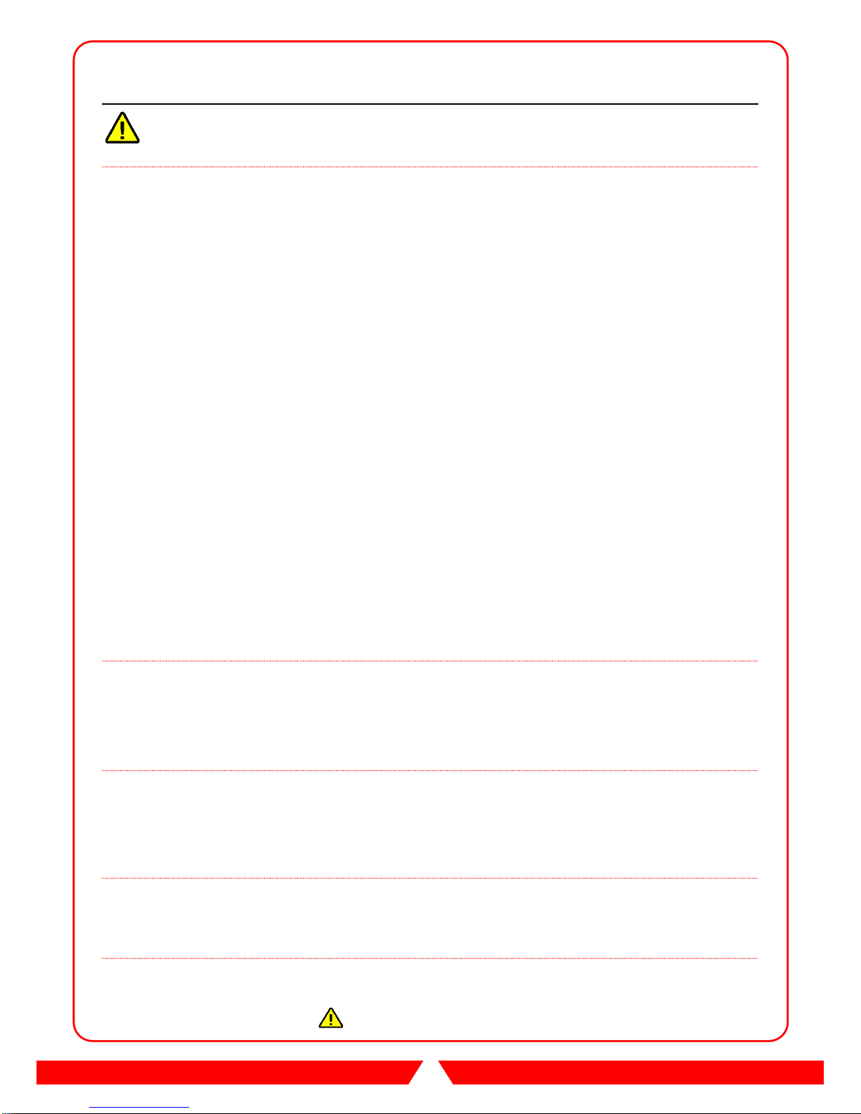
2 SYSTEM SETTING
Electronic Counter
Free play button:Counter no active when press button.
Test button:For test the Doll & sensor active functional.。
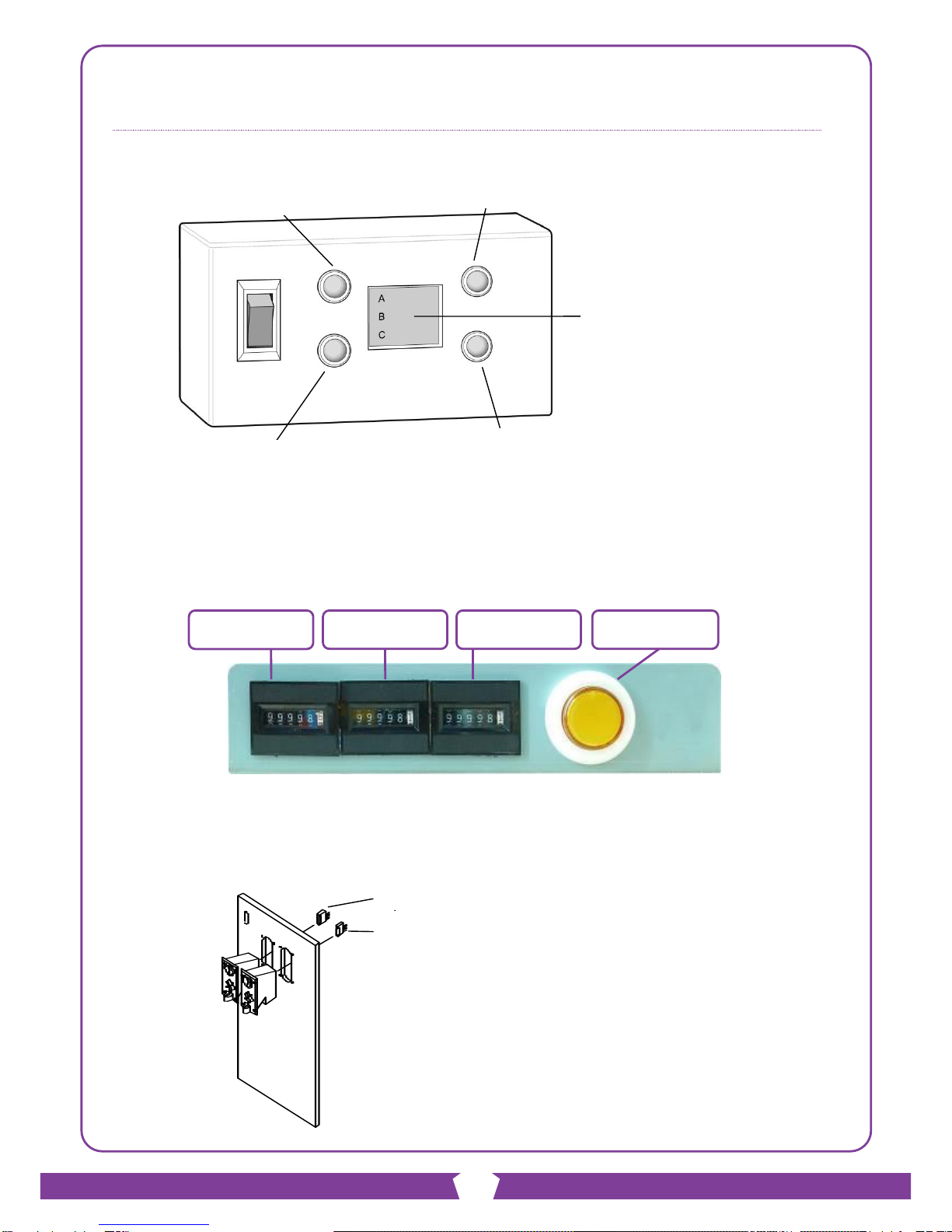
Mechanical counters and FREE PLAY button (Optional)
※TEST button: The micro switch installed on coin box
Coin Selector
Coin Counter 1
FREE PLAY
Ticket Counter
Coin Counter 2
A:Coin Mech 1 Counter
B:Coin Mech 2 Counter
C:Tickets Payout Counter
①FREE PLAY
③RESERVE
②TEST
④RESERVE
Coin Selector 1 -White single
wire.
Coin Selector 2 -Gray single wire.

6
GAME INTRODUCTION
3 HOW TO CLEAR SCORE, COIN AND TICKET RECORD
(1) Keep pressing TEST button and turn on the machine. Release the button when it
shows “222” on display and it will show “001” for reset item 1.
(2) Press TEST button to reset and it will alarm once.
(3) Press FREE PLAY button to enter next item.
Reset items list:
[001] : Score for last game (The default value will be 10 points)
[002] : Coin memory
[003] : Tickets memory
[004] : Change evil minion score. (1-4 points)
※[004] HOW TO CHANGE EVIL MINION SCORE
1) Press and hold FREE PLAY button and switch the machine on.
2) Release the FREE PLAY button when the displays show “222”. The SCORE
display now shows “001”.
3) Press the FREE PLAY button 3 times. The SCORE display now shows “004”
which is the setting for evil minion score. The CREDIT display shows the
points per score for the evil minion which ranges from 01 to 04. Pressing the
TEST button changes the points per score for the evil minion.
4) After setting the evil minion score, reboot the machine or press the FREE
PLAY button once to go to game mode.
(4) Reboot the machine after reset
4 HOW TO TEST THE COIL
In stand-by mode, press TEST button to test coil.
(1) All coils will be off for initial test. If there is any coil (figure) is rising or its sensor is
on, it will alarm correspondent error code. It maybe caused by sensor or coil
malfunctioning.
(2) Test mode stage 2, Minion figures positioning test:All figures turn to Minion side
to check SW and then figures rise one by one to make sure it rising smoothly. If
any figure doesn’t rise smoothly or its sensor is malfunctioning, it alarms and
shows error code accordingly on display.
(3) Test mode stage 3, Evil Minion figures positioning test:All figures turn to Evil
Minion side to check SW and then figures rise one by one to make sure it rising
smoothly. If any figure doesn’t rise smoothly or its sensor is malfunctioning, it
alarms and shows error code accordingly on display.

7
GAME INTRODUCTION
5 FIGURE MECHANISM
(1) Press down or pull the doll when game proceeding will be not cause any
breakdown.
(2) Malfunction by 1 or 2 of the doll won't effect others.
(3) Test progress: Test button on the counter base.
Press "TEST" button to test each doll, please check the "Elimination of
Malfunction"
if there has any breakdown.
(4) The Coil is equipped with temperature protection to prevent overheated.
SPARE BELTS
REDUCING FIGURE SW
ROTATION
BELTSOLENOI
D
FIGURE UP-DOWN SENSOR
ROTATION
MOTOR (DC12V)
COIL/ SOLENOID
SCORE FIGURE
SW

8
GAME INTRODUCTION
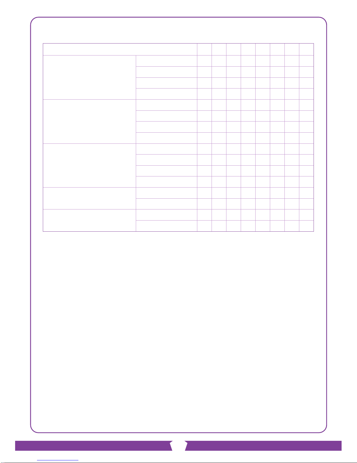
6 DIP SWITCH SETTING
DIP SW 1 1=ON 0=OFF
FUNCTION /DIP
1
2
3
4
5
6
7
8
COIN 1
1 COIN 1 CREDIT
0
0
1 COIN 2 CREDITS
1
0
1 COIN 4 CREDITS
0
1
1 COIN 5 CREDITS
1
1
COIN 2
1 COIN 1 CREDIT
0
0
1 COIN 2 CREDITS
1
0
1 COIN 4 CREDITS
0
1
1 COIN 5 CREDITS
1
1
CREDIT(S) PER PLAY
1 CREDIT
0
0
2 CREDITS
1
0
3 CREDITS
0
1
4 CREDITS
1
1
MAXIMUM
TICKET PAYOUT
UNLIMITED
0
20 TICKET
1
FIGURE SELF-CHECK
WHEN BOOTING
(ALARM IF 3 FIGURES
OR ABOVE FAILED)
N
0
Y
1
Remark : Reboot the machine if the DIPSW setting changed.
9
GAME INTRODUCTION
DIP SW 2 1=ON 0=OFF
FUNCTION /DIP
1
2
3
4
5
6
7
8
TICKET PAYOUT
5 POINTS 1 TICKET
0
0
0
10 POINTS 1 TICKET
1
0
0
20 POINTS 1 TICKET
0
1
0
30 POINTS 1 TICKET
1
1
0
40 POINTS 1 TICKET
0
0
1
50 POINTS 1 TICKET
1
0
1
60 POINTS 1 TICKET
0
1
1
70 POINTS 1 TICKET
1
1
1
MERCY TICKET
0 TICKET
0
1 TICKET
1
ATTRACT MUSIC
TIME INTERVAL
10 MINUTES
0
0
0
1 MINUTE
1
0
0
2 MINUTES
0
1
0
3 MINUTES
1
1
0
5 MINUTES
0
0
1
6 MINUTES
1
0
1
8 MINUTES
0
1
1
DISABLE
1
1
1
TICKET PAYOUT
N
0
Y
1
Remark : Reboot the machine if the DIPSW setting changed.
10
GAME INTRODUCTION
DIP SW 3 1=ON 0=OFF
FUNCTION /DIP
1
2
3
4
5
6
7
8
GAME TIME FOR STAGE 1
30 SECONDS
0
0
40 SECONDS
1
0
50 SECONDS
0
1
60 SECONDS
1
1
GAME TIME FOR STAGE 2
10 SECONDS
0
0
20 SECONDS
1
0
30 SECONDS
0
1
40 SECONDS
1
1
PASS SCORE FOR STAGE 1
40
0
0
50
1
0
60
0
1
80
1
1
POINT DEDUCTION
N
0
Y
1
AUTO RUN
N
0
Y
1
Point deduction : Deduct 1 point when hitting Minion.
The point deduction can be disabled by DIPSW 3-7.
Remark : Reboot the machine if the DIPSW setting changed.
11
WIRING DIAGRAM
WIRING DIAGRAM
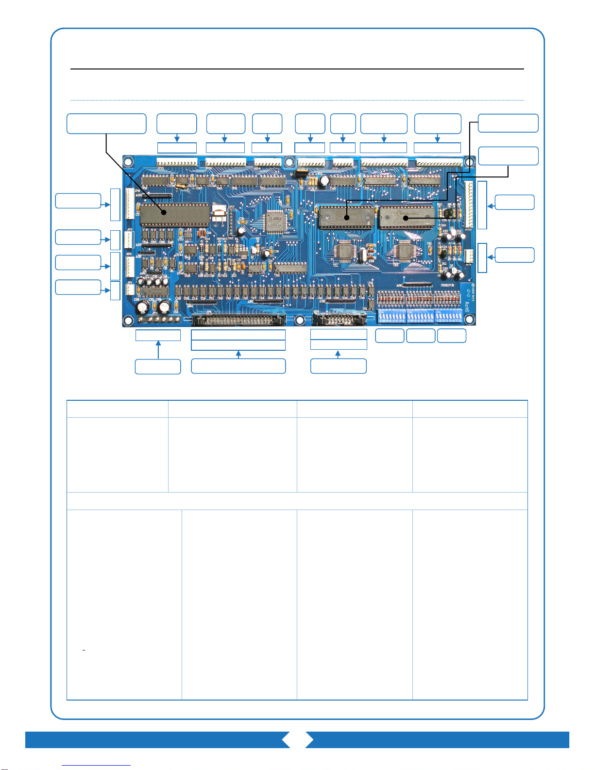
1 DIAGRAM OF MAIN BOARD
JP1
JP2 (Coin Selector)
JP3 (Sound Out Put)
JP4 (Power Input)
NO USE
1. (Yellow)Coin Selector 1 V+
2. (White) Coin Selector 1 Input
3. (Black)Coin Selector 1 GND
4. (Yellow)Coin Selector 2 V+
5. (Grey)Coin Selector 1 Input
6. (Black)Coin Selector 1 GND
1. (White)Out Put
2. No Use
3. GND
4. GND
1. (Yellow)+12V
2. (Yellow).+12V
3. (Black)GND
4. (Black)GND
5. (Red)+5V
6. (Red)+5V
JP5 (HITTING DETECTOR)
1.(Brown) Figure Sensor 1
3.(Grey) Figure Sensor 6
5. (Black in Brown) Evil
Minion 1 SW
7. (White in Brown) Minion 1
SW
9.(Orange) Figure Sensor 2
11. (Black in Orange) Evil
Minion 2 SW
13. (White in Orange) Minion
2 SW
15. (Black in Blue) Evil
Minion 3 SW
17.(Green) Figure Sensor 3
19.(White in Green) Evil
Minion 3 SW
21.(Black in Blue) Evil Minion
4 SW
23.(White in Blue) Minion 4
SW
25.(Blue) Figure Sensor 4
27.(Black in Purple) Evil
Minion 5 SW
29.(White in Purple) Minion 5
SW
31.No Use
33.(Purple) Figure Sensor 5
35.(Black in Yellow) Evil
Minion 6 SW
37.(White in Yellow) Minion 6
SW
39.No Use
2.(Yellow)+12V
4.(Yellow)+12V
6.(Yellow)+12V
8.(Yellow)+12V
10.(Yellow)+12V
12.(Yellow)+12V
14.+12V
16.+12V
18.+12V
20.+12V
22.(Black)GND
24.(Black)GND
26.(Black)GND
28.(Black)GND
30.(Black)GND
32.(Black)GND
34.GND
36.GND
38.GND
40.GND
1 12
JP15
1 12
JP16
1 8
JP14
1 8
JP13
1 6
JP9
1 14
JP11
1 14
JP10
14
1
JP12
4
1
JP3
2 4 6…16
JP6
13 5…15
2 4 6…40
JP5
1 3 5…39
1 6
JP4
1
9
1
5
1
6
JP8
1
3
JP7
JP2
JP1
MAIN PROGRAM IC
SOUND IC (U9)
SOUND IC (U8)
SW1
SW2
SW3
12
WIRING DIAGRAM
JP6 (NO USE)
JP7 (Ticket Dispenser)
JP8 (In/Out Counter)
1.No Use
3.No Use
5.No Use
7.No Use
9.No Use
11.NC
13.NC
15.+12V
2.GND
4.GND
6.GND
8.GND
10.+12V
12.+12V
14.+12V
16.+12V
1. Ticket Dispenser
(Tecway)
2. (Blue)Ticket Detector
3. (White)Ticket Dispenser
(Yenox)
4. (Black)GND
5. (Red)+12V
1. (Black)Free Play GND
2. (Brown)Free Play
3. (Black)Test SW GND
4. (Green)Test SW
5. GND
6. (Yellow)+12V
7. (Blue)In Counter1
8. (Purple)In Counter
9. (Grey)Out Counter
JP9(Demo Light 2)
JP10(Score Display)
JP11(Time Display)
JP12 (RECORD)
1. +12V(Yellow)
2. Demo Light-Middle
Right(Purple)
3. Demo Light-Down Right
(Grey)
4. No Use (IN)
5. No Use (IN)
6. GND(Black)
1. (Black)light D0
2. (Brown)light D1
3. (Red)lightD2
4. (Orange)light D3
5. (Yellow)light D4
6. (Green)light D5
7. (Blue)light D6
8. (Black)light D7
9. (Brown)units digit driver
10. (Red)tens digit driver
11. (Orange)hundreds' digit
12. (Yellow)VCC
13. (Green)+12V
14. (Blue)GND
1. (Black)light D0
2. (Brown)light D1
3. (Red)lightD2
4. (Orange)light D3
5. (Yellow)light D4
6. (Green)light D5
7. (Blue)light D6
8. (Black)light D7
9. (Brown)units digit driver
10. (Red)tens digit driver
11. (Orange)hundreds' digit
12. (Yellow)VCC
13. (Green)+12V
14. (Blue)GND
1. (Black)light D0
2. (Brown)light D1
3. (Red)lightD2
4. (Orange)light D3
5. (Yellow)light D4
6. (Green)light D5
7. (Blue)light D6
8. (Black)light D7
9. (Brown)units digit driver
10. (Red)tens digit driver
11. (Orange)hundreds' digit
12. (Yellow)VCC
13. (Green)+12V
14. (Blue)GND
JP13 (Demo Light 1)
JP14 (Head Driver)
JP15 (Cover LED)
JP16 (Figure Rotating)
1. (Yellow)+12V
2. (Yellow)+12V
3. (Brown) Demo Light-Up
Left
4. (Orange) Demo
Light-Middle Left
5. (Green) Demo
Light-Down Left
6. (Blue) Demo Light-Up
Right
7. GND
8. GND
1. (Brown) Figure Enable 1
2. (Orange) Figure Enable 2
3. (Green) Figure Enable 3
4. (Blue) Figure Enable 4
5. (Purple) Figure Enable 5
6. (Grey) Figure Enable 6
7. (Yellow)+12V
8. (Yellow)+12V
1. (Yellow)+12V
2. (Yellow)+12V
3. (White in Brown) Figure
LED 1
4. (White in Orange) Figure
LED 2
5. (White in Green) Figure
LED 3
6. (White in Blue) Figure
LED 4
7. (White in Purple) Figure
LED 5
8. (White in Grey) Figure
LED 6
9. NO USE
10. NO USE
11. NO USE
12. NO USE
1. (Black in Brown) Figure 1
Rotating
2. (Black in Orange) Figure
2 Rotating
3. (Black in Green) Figure 3
Rotating
4. (Black in Blue) Figure 4
Rotating
5. (Black in Purple) Figure 5
Rotating
6. (Black in Grey) Figure 6
Rotating
7. (Black in Yellow) Goggle
LED
8. NO USE
9. NO USE
10. NO USE
11. (Yellow)+12V
12. (Yellow)+12V
13
WIRING DIAGRAM
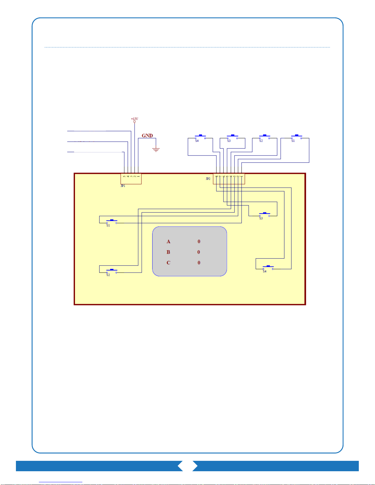
2 ELECTRONIC METER DIAGRAM
Button S1:FREE PLAY Button
Button S2:TEST Button
Button S3:NO USE
Button S4:NO USE
Meter 1(A)
Meter 2(A)
Output Meter(C)

14
WIRING DIAGRAM
3 SYSTEM WIRING DIAGRAM
1 12
JP15
1 12
JP16
1 8
JP13
1 6
JP9
1 14
JP11
1 14
JP10
14
1
SW1
SW2
SW3
1 8
JP14
4
1
1
9
JP8
1
5
JP7
JP
12
1
6
JP2
1
3
JP1
1 6
JP4
2 4 6 8,….40
JP5
1 3 5 7,….39
2 4 6,…. 16
JP6
1 3 5,…. 15
Coin Selector
TICKET DISPENSER
BUTTON / Electronic Counter
AC DRIVER BOARD
6X1
COIL PCB
X6
COIL
X6
TIME/RECORD DISPLAY
SCORE DISPLAY
SOUND
OUTPUT
VOLUME
ADJUST
CREDIT/TICKET DISPLAY
HITTING DETECTOR
U SHAPE SENSOR X 6
ANTI-INTERFERENCE
FILTER
PLUG
POW
ER
DETECTOR
+FIGURE ROTATING SW
HEAD DRIVER
DISPLAY
DISPLAY
DISPLAY
FIGURE ROTATING
DRIVE BOARD X2
GOGGLE LED
PORTS
FIGURE LED
DRIVE PORTS
X6
SCORE LED
AC IN
(FOR SYSTEM) POWER SUPPLY
RD-125A-12V7.7A,5V7.7A
(FOR FIGURE MOTORS) POWER SUPPLY
P-06A12 (+12V/8.5A)
AMPLIFIER POWER
FROM POWER SUPPLY

15
TROUBLESHOOTING
TROUBLESHOOTING
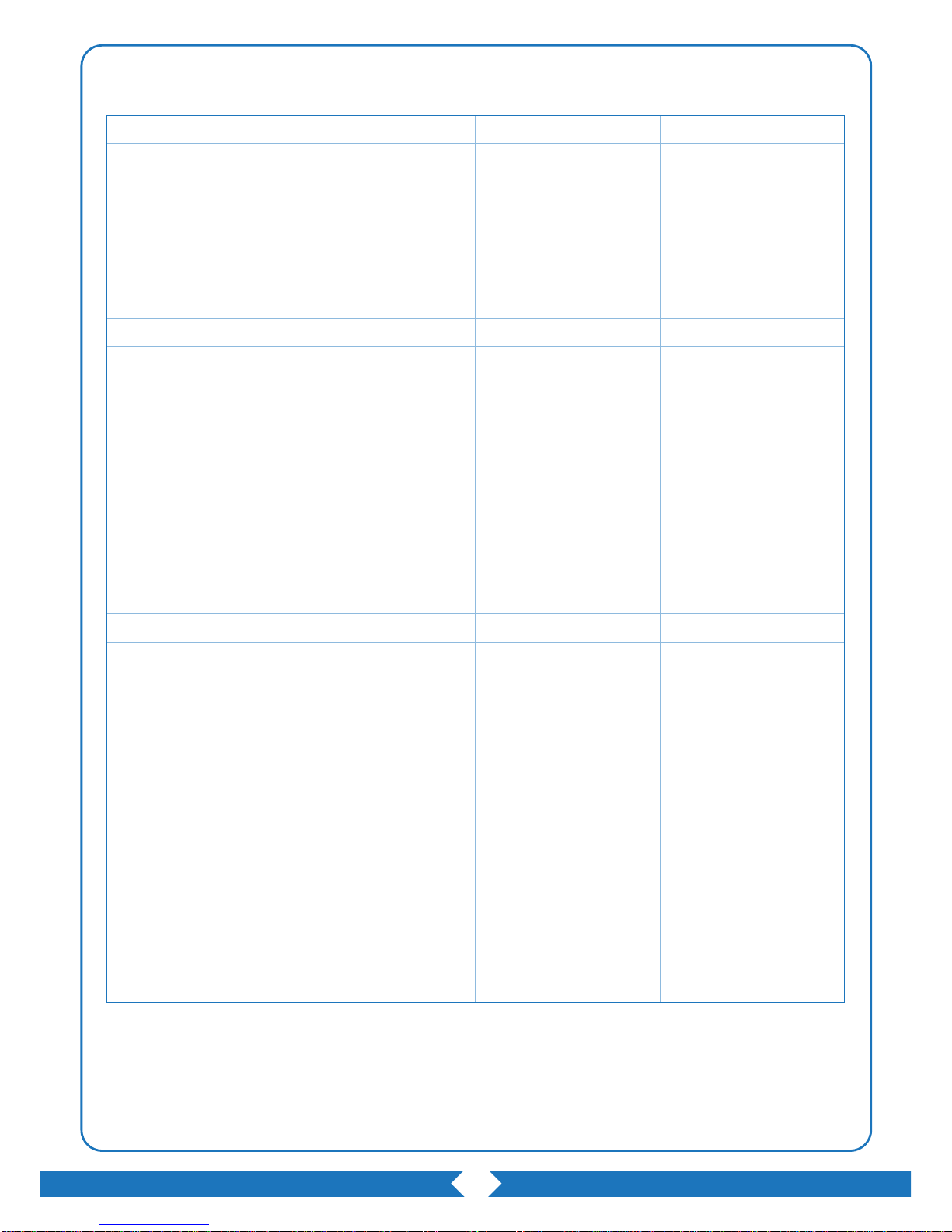
1 ERROR CODE
NO.
ERROR ITEM
SOLUTION
01
Coin Meter 1
(1)Check wire. (2)Replace the Meter.
02
Coin Meter 2
(1)Check wire. (2)Replace the Meter.
03
Ticket Meter
(1)Check wire. (2)Replace the Meter.
04
Coin Selector 1
(1)Check wire. (2)Replace the selector.
05
Coin Selector 2
(1)Check wire. (2)Replace the selector.
06
Memory Card
Replace PCB.
07
Ticket Machine
Check and replenish the token.
11
Coil Set No.1 Error
(1)Check set No.1 and sensor. (2)Replace the sensor.
12
Coil Set No.2 Error
(1)Check set No.2 and sensor. (2)Replace the sensor.
13
Coil Set No.3 Error
(1)Check set No.3 and sensor. (2)Replace the sensor.
14
Coil Set No.4 Error
(1)Check set No.4 and sensor. (2)Replace the sensor.
15
Coil Set No.5 Error
(1)Check set No.5 and sensor. (2)Replace the sensor.
16
Coil Set No.6 Error
(1)Check set No.6 and sensor. (2)Replace the sensor.
21
Structure1 UP SPEED Unusual
(1)check function of structure1
(2)check coil over heat or aging
22
Structure2 UP SPEED Unusual
(1)check function of structure2
(2)check coil over heat or aging
23
Structure3 UP SPEED Unusual
(1)check function of structure3
(2)check coil over heat or aging
24
Structure4 UP SPEED Unusual
(1)check function of structure4
(2)check coil over heat or aging
25
Structure5 UP SPEED Unusual
(1)check function of structure5
(2)check coil over heat or aging
26
Structure5 UP SPEED Unusual
(1)check function of structure6
(2)check coil over heat or aging

16
TROUBLESHOOTING
NO.
ERROR ITEM
SOLUTION
31
EVIL MINION 1 POSITION SW
ERROR
(1) Check position SW
(2) Check rotating mechanism or motor
(3) Check wiring (4) Check drive board
32
EVIL MINION 2 POSITION SW
ERROR
(1) Check position SW
(2) Check rotating mechanism or motor
(3) Check wiring (4) Check drive board
33
EVIL MINION 3 POSITION SW
ERROR
(1) Check position SW
(2) Check rotating mechanism or motor
(3) Check wiring (4) Check drive board
34
EVIL MINION 4 POSITION SW
ERROR
(1) Check position SW
(2) Check rotating mechanism or motor
(3) Check wiring (4) Check drive board
35
EVIL MINION 5 POSITION SW
ERROR
(1) Check position SW
(2) Check rotating mechanism or motor
(3) Check wiring (4) Check drive board
36
EVIL MINION 6 POSITION SW
ERROR
(1) Check position SW
(2) Check rotating mechanism or motor
(3) Check wiring (4) Check drive board
41
MINION 1 POSITION SW
ERROR
(1) Check position SW
(2) Check rotating mechanism or motor
(3) Check wiring (4) Check drive board
42
MINION 2 POSITION SW
ERROR
(1) Check position SW
(2) Check rotating mechanism or motor
(3) Check wiring (4) Check drive board
43
MINION 3 POSITION SW
ERROR
(1) Check position SW
(2) Check rotating mechanism or motor
(3) Check wiring (4) Check drive board
44
MINION 4 POSITION SW
ERROR
(1) Check position SW
(2) Check rotating mechanism or motor
(3) Check wiring (4) Check drive board
45
MINION 5 POSITION SW
ERROR
(1) Check position SW
(2) Check rotating mechanism or motor
(3) Check wiring (4) Check drive board
46
MINION 6 POSITION SW
ERROR
(1) Check position SW
(2) Check rotating mechanism or motor
(3) Check wiring (4) Check drive board

ENCLOSURE
17
ENCLOSURE
1 WARRANTY
a. Please be prepared to provide the following information for place a warranty request:
(1) The Machine type or product number.
(2) Serial Number of Game or Commercial Invoice of Sale.
(3) A Detailed Description of the Equipment Fault Symptoms.
b. All product of Feiloli is warranted as follows:
(1) Main PCB and Computer: 12 Months since produce finished.
(2) Major Mechanism and Kit: 12 Months since produce finished.
(3) All other components: 180 days since produce finished.
( i.e. ticket dispenser, coin selector, bill acceptor, printer, LCD, hopper,
transformer, card dispenser, and etc. )
(4) All repaired items: 90 days since produce finished.
( i.e. Light, hammer, fan, motor, figure, power supply, transmission belt, and etc. )
c. Please note:
(1) Major Mechanism and Kit request to return for repair or replacement.
(2) Damage through transportation will be cover by Feiloli after issue has been
confirmed.
(3) The warranty of replacement will be warranted as same as machines or no
longer than 90 days since replaced.
(4) The copy of warranty is not transferable and applies only to first purchaser.
(5) These statements do not contain any warranty due to improper installation,
accidents, natural disasters, abuse, misuse, inadequate or excessive volts power
supply, improper operation, poor environmental conditions and any unauthorized
disassembly, repair, or product damage caused by the changes.
(6) These warranty statement does not apply to warranty sticker has been to modify,
alter or remove the tear of the product.
The product with packaging damaged, incomplete, second-hand resale or any
violation of national resale product.
Data criteria of warranty has been advice as warranty sticker.
(7) Warranty does not include copies of third-party, or the connected devices.
Any warranty requirements, the force's responsibility of Feiloli is only to replace
the products to consumers. The cost of repair and shipping required by the
purchaser.

© FEILOLI Co. Ltd..All Rights Reserved
Table of contents
Other FEILOLI Arcade Game Machine manuals

Popular Arcade Game Machine manuals by other brands


LIGHT & WONDER
LIGHT & WONDER Kascada SK-1V227ST Service manual

Sega
Sega SHOOT THIS WIN THIS Service manual

Bob's Space Racers
Bob's Space Racers DOG POUNDER AIR Operation manual

Atari
Atari ASTEROIDS Operation, maintenance and service manual

UNIS
UNIS Extreme Shot Operation manual

Raw Thrills
Raw Thrills Bust-a-Move Frenzy Operator's manual

Sega
Sega ALL AIR TRIX DLX Service bulletin

Merit
Merit Ion Rx Removal/Installation Instructions

Incredible Technologies
Incredible Technologies SilverStrike 2009 Bowler's Club Operation manual

Ice
Ice Hoopla Service manual

Sega
Sega HOUSE OF THE DEAD 4 SUPER DELUXE owner's manual

Nintendo
Nintendo POPEYE TPP2-UP Operation manual