Femi 1050 3D Specification sheet

ISTRUZIONI PER L’USO E MANUTENZIONE
INSTRUCTIONS FOR USE AND MAINTENANCE
GEBRAUCHSANLEITUNGEN UND WARTUNG
MODE D’EMPLOI ET ENTRETIEN
INSTRUCCIONES PARA EL USO Y MANUTENCION
INSTRUÇÕES DE UTILIZAÇÃO
CERTIFICATA
CERTIFIED
GEPRÜFT
CERTIFIE
CERTIFICADA
CERTIFICADA
TRONCATRICE CIRCOLARE / MITRE–SAW
KREISSÄGE / SCIE A ONGLET
TRONZADORA / SERRA CIRCULAR
Art. 1050 3D
www.femi.it
CONSERVARE PER UTILIZZI FUTURII / PLEASE RETAIN FOR FUTURE REFERENCE
FÜR KÜNFTIGEN BEDARF AUFBEWAHREN / A CONSERVER POUR DE PROCHAINES UTILISATIONS
¡CONSERVAR PARA USOS FUTUROS! / GUARDAR PARA USAR NO FUTURO

DICHIARAZIONE DI CONFORMITÁ CE DEL COSTRUTTORE
Via Del Lavoro, 4 – 40023 Castel Guelfo (BO) – ITALY
Tel. +39-0542/487611 Fax +39-0542/488226 – http://www.femi.it
FEMI S.p.A.
Dichiara sotto la propria esclusiva responsabilità che questa macchina è conforme alle disposizioni della Direttiva Macchine
2006/42/CE ed è identico, in quanto incluso nell’ allegato IV della direttiva, al macchinario oggetto della certifi cazione CE di
tipo (vedi etichetta riportata) rilasciata da ICE Istituto Certifi cazione Europea S.p.A, organismo notifi cato n. 0303. E’ inoltre
conforme alle disposizioni delle seguenti altre direttive: 2006/95/CE - 2004/108/CE - 2011/65/UE - 2012/19/UE.
COMPLIANCE DECLARATION CE OF THE BUILDER
Via Del Lavoro, 4 – 40023 Castel Guelfo (BO) – ITALY
Tel. +39-0542/487611 Fax +39-0542/488226 – http://www.femi.it
FEMI S.p.A.
Declare under our sole responsibility that the machine,to which this declaration relates, is in conformity with the regulations indicated in
Machinery Directive EC/2006/42 and is identical, in that it is included in appendix IV of the directive, to the machinery concerning CE
certifi cation type (see relative label) issued by the ICE (Istituto Certifi cazione Europea SpA), Notifi ed Body no. 0303. Furthermore it is
also in conformity with the following standards: EC/2004/108 - EC/2006/95 - 2011/65/EU - 2012/19/EU.
CE KONFORMITATS ERKLARUNG DES HERSTELLER
Via Del Lavoro, 4 – 40023 Castel Guelfo (BO) – ITALY
Tel. +39-0542/487611 Fax +39-0542/488226 – http://www.femi.it
FEMI S.p.A.
Erklärt unter seiner alleinigen Verantwortung, dass diese Maschine den Bestimmungen der Maschinenrichtlinie 2006/42/
EG entspricht, und, insofern eingeschlossen in Anhang IV der Richtlinie, identisch mit der maschinellen Ausrüstung ist,
die Gegenstand der EG–Baumusterbescheinigung ist (siehe das abgebildete Etikett), die vom ICE (Istituto Certifi cazione
Europea SpA, anerkannte Prüfstelle Nr. 0303) erlassen wurde. Sie entspricht ferner den Bestimmungen der folgenden
weiteren Richtlinien: 2004/108/EG - 2006/95/EG - 2011/65/UE - 2012/19/UE.
DECLARATION DE CONFORMITE CE DU CONSTRUCTEUR
Via Del Lavoro, 4 – 40023 Castel Guelfo (BO) – ITALY
Tel. +39-0542/487611 Fax +39-0542/488226 – http://www.femi.it
FEMI S.p.A.
Déclare, sous sa propre responsabilité, que cette machine est conforme aux dispositions de la Directive Machines 2006/42/
CE et est identique, car incluse dans l’annexe IV de la directive, à la machine objet de la certifi cation CE de type (voir étiquette
rapportée) remise par ICE Istituto Certifi cazione Europea SpA, organisme notifi é n° 0303. En outre, elle est conforme aux
dispositions des autres directives suivantes : 2004/108/CE - 2006/95/CE - 2011/65/UE - 2012/19/UE
DECLARATION DE CONFORMIDAD CE DEL CONSTRUCTOR
Via Del Lavoro, 4 – 40023 Castel Guelfo (BO) – ITALY
Tel. +39-0542/487611 Fax +39-0542/488226 – http://www.femi.it
FEMI S.p.A.
Declara bajo su exclusiva responsabilidad que esta máquina cumple con lo dispuesto por la Directiva Máquinas 2006/42/
CE y es idéntica, en cuanto máquina que fi gura en el anexo IV de la directiva, a la máquina objeto de la certifi cación CE de
tipo (véase etiqueta ilustrada) otorgada por ICE Instituto de Certifi cación Europea SpA, organismo notifi cado nº 0303.
Asimismo, cumple también con lo dispuesto por las siguientes directivas: 2004/108/CE - 2006/95/CE - 2011/65/UE -
2012/19/UE.
DECLARAÇÃO DE CONFORMIDADE CE DO CONSTRUCTOR
Via Del Lavoro, 4 – 40023 Castel Guelfo (BO) – ITALY
Tel. +39-0542/487611 Fax +39-0542/488226 – http://www.femi.it
FEMI S.p.A.
Declaramos sob a nossa exclusiva responsabilidade que esta máquina está em conformidade com as disposições da Directiva
Máquinas 2006/42/CE e que é idêntica, porque contemplada no anexo IV da directiva, ao maquinário objecto da certifi cação CE
de tipo (ver a etiqueta indicada) emitida por ICE Istituto Certifi cazione Europea SpA, organismo notifi cado nº 0303. Está também
em conformidade com as disposições das seguintes directivas: 2004/108/CE - 2006/95/CE - 2011/65/UE - 2012/19/UE.
Persona autorizzata a costituire il fascicolo tecnico
Person authorized to create the technical fi le
Zur Ausarbeitung der technischen Dokumentation bevollmächtigte Person
Personne autorisée à établir le dossier technique
Persona autorizada a crear el documento técnico
Pessoa autorizada a constituir o fascículo técnico
MAURIZIO CASANOVA
Via Del Lavoro, 4 - Castel Guelfo
Castel Guelfo (BO), 25/03/2011

IT
1
1 INTRODUZIONE ALL’USO
ATTENZIONE: prima di iniziare le lavorazioni con
la Vostra troncatrice, leggete attentamente questo
manuale di istruzioni, allo scopo di conoscere
la macchina, i suoi impieghi, e le eventuali
controindicazioni.
Conservate con cura questo manuale: esso fa parte
integrante della macchina, e ad esso dovrete sempre
riferirvi per eseguire al meglio e nelle massime condizioni di
sicurezza le operazioni che in esso sono descritte.
Il manuale và conservato sempre insieme alla macchina, a
portata di mano per potere essere consultato ogni volta si
renda necessario.
Utilizzate la macchina solo ed esclusivamente per gli impieghi
di seguito specifi cati, usandola come raccomandato in questo
manuale, evitando assolutamente di manometterla o forzarla,
o di usarla per scopi non previsti.
L’operatore deve essere adeguatamente istruito sull’ uso, le
regolazioni e le operazioni eseguibili dalla macchina.
1.1 SIMBOLOGIA UTILIZZATA NEL MANUALE
Porre particolare attenzione ai richiami “ATTENZIONE”,
“CAUTELA” e “NOTE” riportati in questo manuale.
Al fi ne di attirare l’attenzione e dare messaggi di sicurezza le
operazioni pericolose sono precedute da simboli e note che
ne evidenziano la pericolosità e spiegano come comportarsi
per evitare il pericolo.
Questi simboli e note sono di tre categorie cosi identifi cati :
ATTENZIONE: comportamenti rischiosi che
potrebbero provocare gravi lesioni.
CAUTELA: comportamenti che potrebbero causare
lesioni non gravi o danni alle cose.
NOTE: le note precedute da questo simbolo sono di
carattere tecnico e facilitano le operazioni.
Doppio isolamento. Questo simbolo signifi ca che
nessun elemento che può condurre la corrente è
accessibile senza l’utilizzo di un utensile. Questi
apparecchi sono privi di conduttore di terra.
Indica il servizio sull’utensile di un puntatore laser.
INDICE 1.2 CARATTERISTICHE TECNICHE
Potenza motore: ...................................................... 1800 W
Tensione di alimentazione e frequenza: ......230 V ~ 50Hz
Velocità : ............................................................. 3600 minˉ¹
Dimensioni MAX della lama: ..................305 x 3,2 x 30 mm
Taglio trasversale a 90°: .................................305 x 90 mm
Taglio obliquo a 45° a destra e a sinistra: .......215 x 90 mm
Taglio inclinato a 45° a sinistra :......................165 x 65 mm
Taglio composto
(trasversale e inclinato a 45° a sinistra): ......... 45 x 70 mm
Sporgenza massima lama piano superiore: .............60 mm
Arresti di taglio destra e sinistra : .... 0°–15°–22,5°–30°–45°
Arresti di inclinazione: .............................................. 0 e 45°
Laser: ...................................Classe 2 (in conformità con la
.......................................norma EN60825–1: 1994+A1+A2)
Peso netto : .................................................................29 kg
Dimensioni imballo: ............................ 990 × 650 × 460 mm
1.3 SICUREZZA E NORMATIVA
La macchina è progettata e costruita secondo le prescrizioni
imposte dalle vigenti Direttive Comunitarie: 2006/42/CE
– 2006/95/CE – 2004/108/CE.
La dichiarazione di conformità CE allegata, unita al marchio
CE posto sul prodotto, costituisce elemento fondamentale e
parte integrante della macchina: garantiscono la conformità
del prodotto alle Direttive di sicurezza sopra citate.
1.4 TIPO DI IMPIEGO E CONTROINDICAZIONI
La troncatrice circolare è stata progettata e realizzata con
l’impiego delle più avanzate tecnologie, ed è in grado di
soddisfare tutte le esigenze di taglio di legno, alluminio e
materie plastiche tipiche del professionista, dell’artigiano e
dell’hobbista ai massimi livelli.
USO CONSENTITO
Essa può tagliare:
– LEGNO DURO E TENERO, NAZIONALE ED ESOTICO,
LUNGO E TRAVERSO VENA.
e con adeguati adattamenti (lama specifi ca e morsetti
solo in modalità troncatrice):
– MATERIE PLASTICHE
– ALLUMINIO E SUE LEGHE
USO NON CONSENTITO
Non è adatta per il taglio di:
– MAGNESIO
– MATERIALI FERROSI, ACCIAI E GHISE E DI
QUALSIASI ALTRO MATERIALE DIVERSO DA
QUELLI SPECIFICATI NELL’USO CONSENTITO, ED
IN PARTICOLARE DI SOSTANZE ALIMENTARI.
– È ASSOLUTAMENTE VIETATO UTILIZZARE LA SEGA
PER IL TAGLIO DI MATERIALI CHE POSSONO, PER
EFFETTO DEL TAGLIO, EMETTERE SOSTANZE
NOCIVE.
– È ASSOLUTAMENTE VIETATO UTILIZZARE LA SEGA
CIRCOLARE SENZA PROTEZIONE LAMA.
– NON FORZATE L’UTENSILE. LA LAVORAZIONE
SARÀ MIGLIORE E MAGGIORMENTE SICURA SE
L’UTENSILE VIENE UTILIZZATO AL RITMO PER IL
QUALE È STATO CONCEPITO
È ASSOLUTAMENTE VIETATO, IN MODALITÀ SEGA
A BANCO, TAGLIARE LEGNO UMIDO.
– È ASSOLUTAMENTE VIETATO UTILIZZARE LAME DA
TAGLIO IN ACCIAIO RAPIDO.
È ASSOLUTAMENTE VIETATO UTILIZZARE LA
MACCHINA PER EFFETTUARE TAGLI CIECHI.
1 INTRODUZIONE ALL’USO ........................................1
2 INSTALLAZIONE .......................................................4
3 REGOLAZIONI ...........................................................5
4 UTILIZZAZIONE – AVVERTENZE DI SICUREZZA...5
5 ACCESSORI ..............................................................6
6 MANUTENZIONE ......................................................7
7 GUIDA ALLA LOCALIZZAZIONE DEI GUASTI ........8
Manuale originale

IT
2
– Scollegate l’utensile dalla rete quando non è utilizzato,
prima della manutenzione e della sostituzione degli
accessori o utensili quali lame, punte, frese, ecc.,
– Rimuovere i perni di regolazione e le chiavi. È buona
norma controllare se le chiavi di regolazione sono state
rimosse dall’attrezzo prima di accenderlo.
– Evitare l’avvio accidentale. Assicuratevi che l’interruttore
sia nella posizione di arresto prima di collegare
l’utensile.
– Utilizzate delle prolunghe elettriche previste per l’esterno.
Quando l’utensile viene utilizzato all’esterno, utilizzate
solamente delle prolunghe elettriche previste perl’esterno
e che riportino delle indicazioni in merito.
– Controllare i particolari dell’utensile per verifi care che
non ci siano parti danneggiate.
Prima di continuare ad utilizzare l’utensile, controllare
tutti i dispositivi di sicurezza o qualsiasi altro pezzo
che possa essere danneggiato in modo da assicurarvi
che funzioni bene e che riesca ad effettuare il compito
previsto. Verifi care che i pezzi mobili siano ben allineati,
non si blocchino e non siano rotti.
Controllare anche il montaggio o qualsiasi altra
condizione che può influenzare il funzionamento.
Qualsiasi pezzo o qualsiasi protezione danneggiata
deve essere riparata o sostituita da un centro di servizio
post–vendita autorizzato.
– Non utilizzare l’utensile se l’interruttore non funziona
correttamente
ATTENZIONE: l’utilizzo di qualsiasi accessorio o
connessione differenti da quanto raccomandato
nel presente documento può presentare rischi di
infortuni alle persone.
Le riparazioni devono essere effettuate esclusivamente
da personale qualifi cato che faccia uso di ricambi originali,
in caso contrario potrebbero insorgere gravi pericoli per
l’utente.
1.6 PRECAUZIONI DI SICUREZZA PER L’UTILIZZO
– Non forzate inutilmente la macchina: una pressione di
taglio eccessiva può provocare un rapido deterioramento
della lama e un peggioramento delle prestazioni della
macchina in termini di fi nitura e di precisione di taglio.
– Nel taglio dell’alluminio e delle materie plastiche è
opportuno utilizzare gli appositi morsetti: i pezzi oggetto
di taglio devono sempre essere tenuti fermamente nella
morsa.
– Evitate partenze accidentali: non tenete premuto il
pulsante di marcia mentre inserite la spina nella presa
di corrente.
– È opportuno l’utilizzo di scarpe antiscivolo quando si
lavora all’esterno.
– Usate gli utensili raccomandati in questo manuale,
se volete ottenere dalla vostra troncatrice le migliori
prestazioni.
– Controllare che le chiavi utilizzate per la manutenzione
e la regolazione siano state tolte dalla macchina prima
di azionarla.
– Assicurarsi che la velocità marcata sulla lama sia almeno
uguale alla velocità marcata sulla macchina.
– Assicurarsi che la porzione di lama sporgente dal pianetto
sia completamente protetta quando si usa la macchina
come troncatrice.
– È assolutamente vietato rimuovere qualsiasi ritaglio o
altre parti del pezzo in lavorazione dall’area di taglio
mentre la macchina è in moto e la testa di taglio è in
posizione di lavoro.
PERSONALE AUTORIZZATO ALL’UTILIZZO DELLA
MACCHINA
La macchina è stata progettata e costruita per essere
utilizzata da personale qualificato, avente il livello di
formazione, di esperienza e di capacità, secondo le seguenti
caratteristiche:
Operatori / Allievi / Apprendisti:
– possono essere sia di sesso maschile sia femminile,
– devono avere una età minima di 14 anni,
– devono poter operare con entrambe le mani,
– devono essere privi di limitazioni nelle capacità fi siche,
– devono avere ricevuto una formazione specifi ca.
1.5 NORME DI SICUREZZA GENERALI
– Mantenete sempre pulita la zona di lavoro dai residui di
lavorazione.
– Evitare l’utilizzo della macchina in luoghi molto umidi o
con presenza di liquidi infi ammabili o di gas.
– Evitare l’utilizzo della macchina all’aperto, quando le
condizioni generali meteo e ambiente non lo consentono
(es. atmosfere esplosive, durante un temporale o
precipitazioni).
– Utilizzare abiti adeguati: evitare di indossare abiti con
maniche larghe od oggetti, come sciarpe, catene o
bracciali, che potrebbero essere agganciati dalle parti
in movimento.
– Indossare sempre i dispositivi personali di protezione:
occhiali antinfortunistici conformi alle norme, guanti di
dimensioni adatte a quelle della mano, cuffi e o inserti
auricolari e cuffi e per il contenimento dei capelli, se
necessario.
– Fate attenzione al cavo di alimentazione: non usatelo
per sollevare la macchina o per staccare la spina dalla
presa, e salvaguardatelo da spigoli vivi, oli e zone con
elevate temperature.
– Tenete lontano le persone non autorizzate e i bambini
dall’utensile: non lasciate che si avvicinino e che vengano
a contatto con esso.
– Quando si rende necessario usare prolungamenti
del cavo di alimentazione, usate solo quelli di tipo
omologato.
– Salvaguardatevi dall’elettrificazione: evitate contatti
con oggetti con messa a terra, come tubi, termosifoni e
frigoriferi.
– Controllate sempre quello che state facendo.
– Evitare l’utilizzo della macchina se siete stanchi.
– Mantenete sempre posizione ed equilibrio ottimali.
– Non lasciate sull’utensile chiavi o strumenti di misura.
– Utilizzate maschere antipolvere adeguate.
– Collegate il dispositivo di aspirazione della polvere. Se
sono previsti dei metodi per il recupero della polvere,
assicuratevi che questi dispositivi siano collegati e
utilizzati correttamente.
– Lavorare in modo sicuro. Ove possibile utilizzare
ganasce o morse per mantenere in posizione il pezzo
in lavorazione. È più sicuro rispetto all’uso delle sole
mani.
– Mantenere gli utensili in perfetto stato. Tenere gli utensili
affi lati e puliti in modo da ottenere un rendimento migliore
e più sicuro.
– Controllare periodicamente i cavi di alimentazione dei
dispositivi e se danneggiati farli riparare da un centro di
assistenza autorizzato.
– Controllare periodicamente i cavi di prolunga e sostituirli
se danneggiati.
– Tenere le maniglie e le impugnature asciutte, pulite e
prive di olio e di grasso.

IT
3
– Tenete sempre le mani lontane dalle zone di
lavorazione mentre la macchina è in movimento; prima
di eseguire qualsiasi operazione rilasciate il pulsante
nell’impugnatura, spegnendo la macchina e facendola
fermare.
– Sostituire il coperchio del girevole, quando usurato.
– Assicurarsi che il sistema di bloccaggio della lama sia
compatibile con il mandrino e adatto allo scopo previsto
dal fabbricante
– Nel taglio di pezzi di grandi dimensioni utilizzate
appropriati supporti laterali
– Condizioni ambientali limite di utilizzo : + 5 °C / + 40 °C,
umidità relativa 50 % a una temperatura massima di +
40 °C
ATTENZIONE: Le vibrazioni durante l’uso reale
della macchina possono essere diverse da quelle
dichiarate, dal momento che il valore totale di
vibrazione dipende dal modo in cui viene utilizzata
la macchina.
È necessario quindi identificare le misure
di sicurezza più appropriate per proteggere
l’operatore, basate su una stima dell’esposizione
nelle condizioni reali di uso.
1.7 PERICOLI E RISCHI RESIDUI
Rischio residuo di esposizione al rumore
Origine del rischio residuo
Sulla troncatrice permangono rischi residui legati alle
emissione acustiche prodotte dalla stessa durante la
lavorazione.
Precauzioni adottate
A bordo delle troncatrici sono apposte le etichette di
segnalazione, indicanti tale rischio e la necessità da parte
degli operatori / manutentori di indossare gli appositi
dispositivi di protezione acustica.
Norme di sicurezza
ATTENZIONE: L’operatore e/o i manutentori
autorizzati, prima di effettuare le lavorazioni,
devono indossare gli appositi dispositivi di
protezione dell’apparato uditivo.
Rischio residuo di danni alla vista dovuti a emissioni
laser
Origine del rischio residuo
Tale rischio è presente in corrispondenza dell’apposito
puntatore laser di cui è dotata la troncatrice.
Precauzioni adottate
In corrispondenza della lampada è presente l’apposita
etichetta, di segnalazione presenza del rischio
residuo.
Norme di sicurezza
ATTENZIONE: evitare assolutamente di fi ssare
direttamente il fascio di luce laser o dirigere lo
stesso verso altre persone.
Rischi residui di natura meccanica:
– Cesoiamento
– Taglio e Sezionamento
– Impigliamento
– Trascinamento e Intrappolamento
Origine dei rischi residui
Sulla troncatrice permangono rischi residui legati al
funzionamento della lama in rotazione nell’uso come
troncatrice, e della lama di taglio nell’uso con pianetto. Questi
rischi sussistono durante le fasi di lavoro, di manutenzione
e di ricerca dei guasti.
Precauzioni adottate
La macchina è dotata delle apposite protezioni di sicurezza
atte a garantire il funzionamento in condizioni di sicurezza.
Norme di sicurezza
ATTENZIONE: L’operatore e/o i manutentori
autorizzati, prima di effettuare le lavorazioni,
devono essere informati della presenza dei
rischi residui sopra citati, devono verificare
che le protezioni della lama siano presenti e
correttamente installate, inoltre devono indossare
gli appositi dispositivi di protezione individuale.
ATTENZIONE: L’operatore e/o i manutentori
autorizzati, prima di effettuare le operazioni
di manutenzione, riparazione o ricerca dei
guasti, devono accertarsi che la macchina sia in
condizione di arresto e scollegata dalla fonte di
energia.
1.8 INFORMAZIONI RELATIVE AL RUMORE E
VIBRAZIONI
Il rumore emesso, misurato conformemente alle norme
EN61029, EN3744 e EN11201 è risultato essere:
– Livello di pressione acustica ................... LpA = 96 dB(A)
– Livello di potenza sonora ..................... LWA = 103 dB(A)
– Incertezza della misura .....................................K = 3 dB
Si consiglia di indossare adeguati protettori
acustistici.
Le sorgenti del rumore della sega sono: il motore elettrico e la
sua ventilazione, il riduttore di velocità, la lama e ovviamente
il materiale da tagliare.
Per il motore e la sua ventilazione si consiglia di tenerlo
controllato e puliti i passaggi dell’aspirazione, per le lame di
utilizzare tipi silenziati, di tenerle sempre in perfetta effi cienza
e per il materiale da tagliare di usare le lame giuste e di tenere
sempre ben bloccati i particolari da tagliare.
I valori indicati per il rumore sono livelli di emissione e non
necessariamente livelli di lavoro sicuro. Mentre vi è una
correlazione tra livelli di emissione e livelli di esposizione,
questa non può essere usata affi dabilmente per determinare
se siano richieste o no ulteriori precauzioni. I fattori che
infl uenzano il reale livello di esposizione del lavoratore
includono la durata dell’esposizione, le caratteristiche
dell’ambiente, altre sorgenti di rumore, per esempio il
numero di macchine e altre lavorazioni adiacenti. Inoltre i
livelli di esposizione possono variare da un Paese a Paese.
Queste informazioni mettono comunque in grado l’utilizzatore
della macchina di fare la miglior valutazione dei pericoli e
dei rischi.

IT
4
2.3 TRASPORTO
Nel caso si renda necessario trasportare la macchina,
rimettetela nella scatola originale nella quale era contenuta
al momento dell’acquisto, facendo attenzione ad inserirla
nella giusta posizione rispetto alle frecce presenti sull’imballo.
Prestate molta attenzione agli ideogrammi stampati sulla
scatola, che forniscono le indicazioni di pallettizzazione e
sovrapposizione di più scatole.
Per quanto possibile, è buona norma fi ssare il carico con
corde o cinghie di sicurezza, per evitare spostamenti e
cadute del carico durante il trasporto.
2.4 POSIZIONAMENTO / POSTO DI LAVORO (Fig.
4–5)
Posizionate la macchina su un banco oppure su un
basamento/piedistallo suffi cientemente piano, in modo da
avere la migliore stabilità possibile.
Per un eventuale fi ssaggio utilizzare gli appositi fori previsti
sulla base.
Per eseguire le lavorazioni tenendo conto dei criteri
ergonomici, l’altezza ideale del banco o del basamento deve
essere quella che vi consente di posizionare il piano della
base, oppure il piano di lavoro superiore, tra i 90 ed i 95 cm.
da terra (vedi Fig. 4).
Il posizionamento della macchina sul posto di lavoro deve
essere eseguito in modo da avere almeno 80 cm di spazio
circostante, in tutte le direzioni, intorno alla macchina,
per potere effettuare con sicurezza e spazio di manovra
sufficiente la pulizia, la manutenzione e le regolazioni
necessarie (vedi Fig. 5).
CAUTELA: Abbiate cura di posizionare la macchina
in una zona di lavoro adeguata sia come condizioni
ambientali che come luminosità: ricordate sempre
che le condizioni generali dell’ambiente di lavoro
sono fondamentali nella prevenzione degli
infortuni.
2.5 COLLEGAMENTO ELETTRICO
Controllate che l’impianto di rete sul quale inserite la
macchina sia collegato a terra come previsto dalle norme
di sicurezza vigenti, e che la presa di corrente sia in buono
stato. Si ricorda all’utilizzatore che a monte dell’impianto
rete deve essere presente una protezione magnetotermica
atta a salvaguardare tutti i conduttori dai corto circuiti e dai
sovraccarichi.
Tale protezione dovrà essere scelta anche in base alle
caratteristiche elettriche della macchina riportate sul
motore.
ATTENZIONE: Prima di collegare la macchina alla
rete verifi care la corretta tensione di alimentazione
secondo le specifiche riportate sul presente
documento e sulla targhetta del motore.
ATTENZIONE: Una volta collegato, accertarsi
che il cavo di alimentazione sia completamente
appoggiato a terra e non sollevato, allo scopo di
evitare possibili rischi residui di inciampo sullo
stesso.
ATTENZIONE : la spina in dotazione è di tipo C
(CEE 7/17) europea a 2 poli
1.9 INFORMAZIONI SULLA COMPATIBILITA’
ELETTROMAGNETICA
Le recenti Normative Europee sulla sicurezza, ed in
particolare la Direttiva 2004/108/CE, prescrivono che tutte le
apparecchiature siano dotate di dispositivi di schermatura per
i radiodisturbi sia da che verso l’ambiente esterno. Questa
macchina è conforme alle prescrizioni. Le prove sono state
eseguite secondo le Norme EN 55014–1, EN 55014–2.
1.10 DESCRIZIONE DELLA MACCHINA (Fig. 1)
La troncatrice circolare è composta da tre parti fondamentali:
il corpo centrale , comprendente il motore 6, che è collegato
alla base 3 tramite lo snodo 4 e il supporto girevole 5, e il
gruppo di lavoro superiore, comprendente il piano di lavoro
15, la squadra di appoggio 17 e la protezione mobile della
lama 16.
La base 3 viene impiegata come appoggio quando si devono
eseguire operazioni di troncatura e intestatura nelle diverse
angolazioni disponibili; il piano superiore viene impiegato
come appoggio quando si devono rifi lare o sezionare tavole
di legno di grandi dimensioni, e in particolare nel taglio del
legno lungo vena.
Legenda Fig. 1
1 Impugnatura di comando
2 Interruttore di marcia
3 Base
4 Motore
5 Lama
6 Leva sblocco graduazione
7 Pulsante di sblocco discesa corpo
8 Protezione fi ssa lama
9 Protezione mobile superiore
10 Estensioni del piano di lavoro
11 Collettore scarico polvere
12 Morsetti ferma pezzo
13 Piano di lavoro superiore
14 Squadra di appoggio
15 Piedi di appoggio
2 INSTALLAZIONE
2.1 RIMOZIONE DELL’IMBALLO
Rimuovete la scatola che protegge la macchina durante
il trasporto, avendo cura di mantenerla intatta, nel caso
dobbiate spostare la troncatrice per lunghi tragitti o
immagazzinarla per lunghi periodi.
2.2 MOVIMENTAZIONE
Date le dimensioni ridotte ed il peso contenuto, la troncatrice
può essere comodamente movimentata, azionando
l’apposito blocco per il trasporto tramite lo spinotto 4 - Fig. 8
e sollevando la macchina (Fig. 2).
ATTENZIONE: Durante il trasporto, la parte
superiore della lama della troncatrice deve essere
coperta. Verifi care sempre che lama sia protetta
dalla apposita protezione superiore.

IT
5
NOTE: L’impianto elettrico della vostra troncatrice
è dotato di relè di minima tensione, che apre
automaticamente il circuito quando la tensione
scende sotto un limite minimo stabilito, e che
impedisce il ripristino automatico della condizione
di funzionamento quando la tensione ritorna ai
livelli nominali previsti.
Se la macchina subisce un arresto involontario
non allarmatevi, ma controllate se effettivamente
sia venuta a mancare la tensione nell’impianto di
rete.
3 REGOLAZIONI
ATTENZIONE: Tutte le operazioni di regolazione
illustrate nei paragrafi seguenti devono essere
effettuate con motore della macchina spento.
ATTENZIONE: La macchina esce di fabbrica già
tarata in tutte le posizioni. Per ulteriori regolazioni
rivolgersi ad un centro di assistenza autorizzato
3.1 REGOLAZIONE DELL’ANGOLO DI TAGLIO–
ROTAZIONE TESTA (Fig. 17)
La troncatrice è in grado di effettuare tagli orientati sia verso
destra che verso sinistra.
Le posizioni fi sse già tarate sono: 15°, 22° 30’, 30° e 45°.
Per ottenere queste posizioni, allentare la manopola 5 - Fig.
9, sbloccate la testa della macchina, spingendo verso il
basso la leva 6 - Fig. 10, e fate ruotare il supporto girevole
tramite la manopola 5.
La testa si arresterà automaticamente quando di volta in volta
l’indice 27 si troverà allineato alla corrispondente posizione
scelta sulla targa graduata del girevole.
Per tutte le posizioni intermedie, una volta allineato l’indice
27 con la posizione sulla targa, bloccate il supporto girevole
tramite la manopola 5.
3.2 REGOLAZIONE DELL’ANGOLO DI TAGLIO–
INCLINAZIONE TESTA (Fig. 18)
ATTENZIONE : assicurarsi che la testa della
macchina sia ben fissata nel caso di tagli
inclinati
La testa della macchina può inclinarsi fi no ad un massimo
di 45° verso sinistra.
Sbloccate la manopola 10 - Fig. 12 e il pomello 9 - Fig.
12 (nella parte posteriore della macchina) ed inclinate la
testa fi no all’arresto sul fermo a 45°, già tarato al momento
del collaudo. Bloccate quindi di nuovo la testa mediante la
manopola 10.
Per tutte le altre posizioni intermedie, fate coincidere l’indice
28 con la corrispondente posizione impressa sulla scala
graduata dello snodo.
ATTENZIONE: Nel taglio a doppia inclinazione
(rotazione più inclinazione testa) tenere il pezzo
saldo alla macchina con il morsetto e guidare la
discesa della testa con la mano destra (Fig. 28).
3.3 REGOLAZIONE ALTEZZA PIANO SUPERIORE
(Fig. 11-21)
SOLO PER SEGA CIRCOLARE
ATTENZIONE: Lavorando sul piano superiore, è
necessario montare il carter di protezione inferiore
11 - Fig. 19 in dotazione.
Per montare il carter, con la testa sollevata, inseritelo
nell’apposita sede dopo di che abbassate la testa e bloccate
il corpo in questa posizione tramite il perno di bloccaggio
4 - Fig. 20.
Per regolare l’altezza di fuoriuscita della lama dal piano,
in modo da effettuare il taglio dello spessore desiderato,
eseguite le seguenti operazioni:
– Allentate in senso orario la leva 14 - Fig. 21;
– ruotate in senso antiorario il pomello 15 fi no a che la lama
non fuoriesca dal piano all’ altezza desiderata;
– bloccate la leva 14.
3.4 REGOLAZIONE DELLA SQUADRA DI APPOGGIO
(Fig. 19)
SOLO PER SEGA CIRCOLARE
Potete avvicinare o allontanare la squadra di appoggio 14
dalla lama, in modo da eseguire il taglio di tavole di misura
prestabilita.
Allentate il volantino 29, e fate scorrere la squadra 14 facendo
coincidere l’indice sul supporto con la rispettiva posizione
sulla scala graduata ricavata nel piano di lavoro, tenendo
presente che la posizione individuata dalla squadra sulla
scala graduata, corrisponde alla distanza dalla superfi cie
di taglio della lama.
3.6 REGOLAZIONE CUNEO (Fig. 6)
Perchè il cuneo divisore sia nella posizione corretta, tenerlo
ad una distanza tra i 3 mm e gli 8 mm dal dente della
lama.
4 UTILIZZAZIONE – AVVERTENZE DI
SICUREZZA
Una volta eseguite tutte le procedure e le operazioni fi n qui
descritte, potete iniziare le lavorazioni, facendo riferimento
alle seguenti prescrizioni di sicurezza.
ATTENZIONE!
• Tenete sempre le mani lontane dalla zona
di taglio e non cercate in alcun modo di
raggiungerla durante le operazioni.
• È assolutamente vietato utilizzare la macchina
per effettuare tagli ciechi.
• Verifi care sempre, prima di ogni lavorazione, che
pomelli e leve di bloccaggio siano correttamente
serrati.
• È assolutamente vietato utilizzare la macchina
nel caso l’interruttore non accenda né spenga
la macchina stessa.
• Verifi care sempre, prima di azionare le macchina,
che tutte le protezioni siano correttamente
montate e che proteggano adeguatamente la
lama.
• Controllare eventuali parti danneggiate

IT
6
4.1 USO COME TRONCATRICE (Fig. 7 – 8 – 14)
– Sbloccate la testa, svitando il perno di blocco 4 e bloccate
il movimento radiale a fi ne corsa posteriore tramite il
pomello 3.
– Sollevate la testa della macchina fi no alla massima
escursione.
– Assicurate saldamente il pezzo da tagliare contro gli
appoggi angolari della base, con il morsetto, in modo
che non possa muoversi durante il taglio.
– Ponete la mano destra sull’impugnatura 1, e premete
il pulsante 8 in modo da sbloccare il movimento della
testa.
– Azionate il motore premendo il pulsante di marcia I (7 -
Fig. 14) sull’impugnatura.
– Fate scendere la testa, e mettete gradualmente a
contatto la lama con il pezzo da tagliare.
– Eseguite il taglio completo del pezzo, e riportate la testa
nella posizione originale.
– Spegnete il motore premendo il pulsante 0 (7 - Fig.14).
4.1.1 TECNICA DI UTILIZZO CORRETTO PER TAGLI
UTILIZZANDO LO SPOSTAMENTO RADIALE
Avviso : può essere pericoloso tagliare tirando la troncatrice
verso l’operatore, potrebbe saltare verso l’alto e verso
l’operatore.
Spingete sempre la lama all’indietro, allontanandola
dall’operatore e verso la guida quando effettuate un taglio
utilizzando lo scorrimento. I seguenti punti illustrano il
metodo di utilizzo corretto da seguire per utilizzare lo
scorrimento durante un taglio con la vostra troncatrice
radiale combinata:
1. Mettete il pezzo da lavorare sul piano della troncatrice
contro la guida. Tenete l’impugnatura del braccio di taglio
ma non avviate la troncatrice in questo momento.
2. Tirate il braccio verso di voi. Il braccio è in posizione
alta. Una volta tirato il braccio di taglio verso di voi,
premete il pulsante di marcia per mettere in funzione la
troncatrice.
3. Premete il pulsante di sblocco della protezione 8 - Fig.14
e premete sul braccio di taglio verso il basso.
4. Spingete il braccio di taglio all’indietro e verso la guida
per effettuare il taglio.
5. Rilasciate il pulsante di marcia e lasciate il braccio di
taglio in posizione bassa fi no a che la lama si fermi
completamente.
6. Una volta che la lama è ferma, rialzate il braccio di taglio
in posizione alta.
4.2 USO COME SEGA CIRCOLARE (taglio sul piano
superiore) (Fig. 7-11-15-21)
ATTENZIONE: Verificare sempre, prima di
ogni lavorazione sul piano, che la testa della
macchina sia correttamente bloccata in posizione,
completamente abbassata e finecorsa radiale
posteriore.
ATTENZIONE: Lavorando sul piano superiore, è
necessario montare il carter di protezione inferiore
in dotazione (par. 3.3).
ATTENZIONE: La macchina è dotata di spintore 17
di dimensioni e forma conformi a quelle prescritte
dalle norme di sicurezza.
Quando la macchina viene usata come SEGA
CIRCOLARE (utilizzando per le lavorazioni il piano
di lavoro superiore ...) tale accessorio deve essere
OBBLIGATORIAMENTE utilizzato.
Lo spintore è posto sotto al piano superiore (Fig.
22) e va impugnato nella parte A, mentre la parte
B, dotata di diversi gradini per l’adattamento a
spessori differenti, deve essere posta a contatto
con il pezzo da tagliare come mostrato in fi gura 15.
Tramite lo spintore è possibile spingere il pezzo da
tagliare, guidandolo contemporaneamente tramite
l’appoggio sulla squadra C (Fig. 23), e mantenendo
sempre le mani distanti dalla zona di taglio della
lama.
ATTENZIONE: il coltello separatore non deve avere
lo spessore superiore a quello del taglio della lama
e deve essere più sottile del corpo della lama.
– Con motore spento, bloccate il movimento radiale a
fi necorsa posteriore tramite il pomello 3 - Fig. 7 e bloccate
la testa della macchina in posizione abbassata tramite il
perno di blocco 4 - Fig. 20.
– Regolate l’altezza del piano superiore in base all’altezza
di taglio voluta e la squadra di appoggio come descritto
al paragrafo 3.3.
– Controllate il corretto funzionamento della protezione
mobile superiore: dopo averla alzata leggermente,
deve ritornare nella posizione originale, coprendo
completamente la lama.
– Azionate il motore premendo il pulsante di marcia I (7 -
Fig. 14) sull’impugnatura.
– Posizionate la tavola da sezionare sul piano,
appoggiandola lateralmente sulla squadra, e fate
avanzare il pezzo da tagliare in modo regolare e senza
forzature verso la lama.
CAUTELA: Il pezzo da tagliare deve sempre
essere tenuto saldamente, avendo l’accortezza
di impugnarlo lontano dalla linea di taglio della
lama.
– Spegnete il motore premendo il pulsante 0 (7 - Fig.
14).
ATTENZIONE: terminata la fase di lavoro riportare
sempre la lama nella posizione 0 di altezza (Fig.
11).
5 ACCESSORI
ATTENZIONE: L’operatore e/o i manutentori
autorizzati, prima di effettuare le seguenti
operazioni, devono accertarsi che la macchina sia
in condizione di arresto e scollegata dalla fonte di
energia.
5.1 MONTAGGIO E REGOLAZIONE DEl MORSETTI
(Fig. 24)
CAUTELA: Quando dovete tagliare barre o pezzi
di alluminio o di plastica, si consiglia di utilizzare
il morsetto per assicurare il pezzo agli appoggi
angolari, evitando così che si muova durante il
taglio causando inceppamenti che potrebbero
danneggiare il pezzo stesso e la lama.

IT
7
6 MANUTENZIONE
6.1 INTERVENTI DI MANUTENZIONE ORDINARIA
Le normali operazioni di manutenzione ordinaria, effettuabili
anche da personale non specializzato, sono tutte descritte
nei paragrafi precedenti e nel presente.
1. La troncatrice non ha bisogno di alcuna lubrifi cazione,
in quanto il taglio deve essere sempre effettuato a
secco (compreso quello dell’alluminio e delle leghe
leggere); tutti gli organi rotanti della macchina sono
autolubrifi cati.
2. Durante le operazioni di manutenzione, indossate per
quanto possibile i mezzi personali di protezione (occhiali
antinfortunistici e guanti).
3. Rimuovete i trucioli residui di lavorazione ogni qualvolta
si renda necessario, intervenendo nella zona di taglio e
sui piani di appoggio.
E’ consigliato l’uso di un aspiratore o di un pennello.
ATTENZIONE: Non usate getti di aria
compressa!!!
– Prima di eseguire qualunque operazione di riparazione
o manutenzione sezionate l’alimentazione elettrica.
4. Verifi cate periodicamente le condizioni della lama: se
doveste riscontrare diffi coltà nel taglio, fatela affi lare da
personale specializzato, oppure sostituitela, se dovesse
presentarsene la necessità.
5. Verificare periodicamente che l’ arresto della lama
avvenga entro 10 secondi dal rilascio del pulsante e
che la molla del braccio permetta al braccio di risalire
fi no al fermo meccanico in un tempo non superiore ai 2
secondi se questo non avviene fate controllare la vostra
troncatrice da personale autorizzato.
6.2 RIMOZIONE TRUCIOLI
ATTENZIONE: L’operatore e/o i manutentori
autorizzati, prima di effettuare le seguenti
operazioni, devono accertarsi che la macchina sia
in condizione di arresto e scollegata dalla fonte di
energia.
1) In modalità troncatrice, rimuovere immediatamente i
trucioli di legno dopo un breve periodo di funzionamento
per evitare che impediscano il corretto funzionamento
della macchina.
2) In modalità sega a banco, quando l’uscita trucioli risulta
bloccata dopo un lungo periodo o un uso intensivo,
convertire temporaneamente la macchina in modalità
troncatrice e rimuovere i trucioli di legno prima di tornare
all’utilizzo richiesto.
6.3 RIMESSAGGIO MACCHINA QUANDO NON
UTILIZZATA
Quando la macchina non viene utilizzata, predisporla in
modalità sega a banco (Fig. 20).
ATTENZIONE: Conservare con cura la protezione
inferiore 11 - Fig. 19 del banco di lavoro, il quale
non deve andare perduto o danneggiarsi, altrimenti
il funzionamento in modalità sega a banco non
sarà disponibile o gli operatori potrebbero subire
infortuni.
– inserite il perno 31 nell’apposito foro e bloccatelo tramite
il pomello 32
– Inserire il morsetto sul perno 31 e bloccatelo all’altezza
desiderata con il pomello 33.
– Bloccate il pezzo da tagliare girando in senso orario il
pomello 34.
5.2 MONTAGGIO DELLE ESTENSIONI LATERALI
(Fig. 23)
La troncatrice è fornita con due estensioni laterali 23 che
permettono di sostenere durante il taglio i pezzi di legno di
grandi dimensioni. Le estensioni possono essere montate
ai due lati della troncatrice, in funzione delle dimensioni del
pezzo da lavorare. Aprite il pomello di bloccaggio 30, inserite
le estensioni nei fori situati da una parte e dall’altra della base
della troncatrice e richiudete il pomello di bloccaggio 30.
5.3 ISTRUZIONI PER LA SOSTITUZIONE DELLA
LAMA DELLA SEGA (Fig. 25)
ATTENZIONE: Per evitare che i denti della sega
feriscano le mani dell’operatore, questi deve
indossare i guanti di protezione.
ATTENZIONE
• È assolutamente vietato montare lame
che alla vista risultino incrinate. Montare
esclusivamente lame a norma EN 847–1.
• È assolutamente vietato utilizzare lame ad alta
velocità in acciaio.
• Utilizzate sempre lame affi late e di dimensioni
idonee.
Con la testa in posizione di riposo (rialzata), bloccate la
fl angia esterna 19 con la chiave in dotazione, e con l’altra
chiave svitate la vite in senso orario.
Togliere la lama e sostituirla con un’altra, facendo attenzione
che il senso di rotazione indicato dalla freccia sul carter sia
concorde con l’inclinazione di taglio dei denti.
Prima di montare la lama, pulite accuratamente le fl angie
d’appoggio.
Riposizionate la fl angia esterna 20 facendo attenzione al suo
perfetto inserimento sull’albero e stringete la vite.
Riportate il carter 21 in modo da coprire totalmente la
lama.
5.4 ASPIRAZIONE DELLE POLVERI (Fig. 27)
(OPTIONAL)
La troncatrice è predisposta per il collegamento con un
aspiratore, o per il montaggio del sacchetto raccogli polvere,
tramite il collettore di scarico 26.
Il tubo dell’aspiratore o la manichetta del sacchetto devono
essere fi ssati al collettore tramite una fascetta.
Vi raccomandiamo di svuotare periodicamente il sacchetto
o il contenitore dell’aspiratore, e di pulire il fi ltro.
La velocità di uscita dell’aria creata dall’aspiratore deve
essere almeno di 100 Nm3/h. Aspiratori capaci di creare
queste depressioni sono ad esempio quelli di tipo “bidone”.

IT
8
• L’utente dovrà, pertanto conferire l’apparecchiatura
giunta a fi ne vita agli idonei centri di raccolta differenziata
dei rifi uti elettronici ed elettrotecnici, oppure riconsegnarla
al rivenditore al momento dell’acquisto di una nuova
apparecchiatura di tipo equivalente, in ragione di uno a
uno.
• L’adeguata raccolta differenziata per l’avvio successivo
dell’apparecchiatura dismessa al riciclaggio, al
trattamento e allo smaltimento ambientalmente
compatibile contribuisce a evitare possibili effetti
negativi sull’ambiente e sulla salute e favorisce il
reimpiego e/o riciclo dei materiali di cui è composta
l’apparecchiatura.
• Lo smaltimento dei materiali di risulta della manutenzione
deve essere eseguito in conformità alle leggi in vigore
nel paese in cui lo smaltimento viene effettuato.
ATTENZIONE: lo smaltimento abusivo del prodotto
da parte dell’utente comporta l’applicazione delle
sanzioni amministrative previste dalla normativa
vigente.
1. Fate controllare la macchina da personale
specializzato.
Non cercate di riparare da soli il motore:
potrebbe essere pericoloso.
2. Controllate i fusibili e sostituiteli se necessario.
1. Richiedete un controllo della tensione
disponibile da parte dell’Ente erogatore.
2. Fate controllare il motore della macchina da
personale specializzato.
1. Fate controllare il motore da personale
specializzato.
1. Non utilizzate servizi o altri motori sullo stesso
circuito al quale collegate la macchina.
1. Evitare di sovraccaricare il motore durante
l’operazione di taglio.
2. Rimuovere la polvere dal motore per ottenere il
corretto fl usso dell’aria di refrigerazione.
1. Intervenite sulla regolazione del fi ne corsa della
discesa della testa.
1. Fate affi lare la lama da un centro di affi latura
specializzato.
2. Controllate se la dentatura che state usando è
giusta
1. Controllate qual è la giusta dentatura da
utilizzare
Il motore non funziona
Il motore parte lentamente
o non raggiunge la
velocità di funzionamento.
Eccessivo rumore del
motore.
Il motore non sviluppa la
piena potenza.
Il motore tende a
surriscaldare.
Riduzione della capacità
di taglio.
La fi nitura del taglio risulta
grezza o ondulata.
Scheggiatura del pezzo
tagliato.
1. Motore, cavo rete o spina
difettosi.
2. Fusibili bruciati.
1. Bassa tensione di
alimentazione.
2. Avvolgimenti danneggiati.
1. Avvolgimenti danneggiati.
Motore difettoso.
1. Circuiti dell’impianto rete
sovraccaricati da luci, servizi o
altri motori.
1. Il motore è sovraccaricato.
2. Raffreddamento del motore non
adeguato.
1. La lama è stata affi lata molte
volte e si è ridotta di diametro.
1. La lama è consumata oppure
non ha la dentatura adatta allo
spessore del materiale che state
tagliando.
1 La dentatura della lama non
è adatta al pezzo che state
agliando.
PROBLEMA PROBABILE CAUSA RIMEDIO SUGGERITO
6.4 ASSISTENZA
Nel caso sia necessario l’intervento di personale
specializzato per operazioni di manutenzione straordinaria,
oppure nel caso di riparazioni, sia in regime di garanzia che
successivamente, rivolgetevi sempre ad un centro di
assistenza autorizzato, oppure direttamente alla fabbrica, se
nella vostra zona non e’ presente il centro di assistenza.
6.5 SMALTIMENTO MACCHINA, IMBALLAGGIO,
MATERIALI DI RISULTA DELLA MANUTENZIONE
INFORMAZIONE AGLI UTENTI
Attuazione delle Direttive 2011/65/UE - 2012/19/
UE, relative alla riduzione dell’uso di sostanze
pericolose nelle apparecchiature elettriche ed
elettroniche, nonché allo smaltimento dei rifi uti”,
si precisa quanto segue:
• Il simbolo del cassonetto barrato riportato
sull’apparecchiatura o sulla confezione indica che il
prodotto alla fi ne della propria vita utile deve essere
raccolto separatamente dagli altri rifi uti.
7 GUIDA ALLA LOCALIZZAZIONE DEI GUASTI

EN
9
1 INTRODUCTION TO USE
WARNING: before using your mitre–saw, please
read this instruction manual very carefully in
order to become familiar with the machine and
its recommended use.
Do not lose this manual as it is an essential part of the
machine itself. We recommend you always refer to it in
order to operate the machine in the best and safest way
possible.
Keep the manual with the machine and handy at all times
so it can be consulted whenever necessary.
This machine is designed solely and exclusively for
the uses indicated below. Use in accordance with the
recommendations provided in this manual. NEVER tamper
with it, force it or use it for any purpose not envisaged in
these instructions.
The operator is adequately trained in the use, adjustment
and operation of the machine.
1.1 SAFETY INFORMATION AND NOTES
Pay particular attention to the indications “WARNING”,
“CAUTION” and “NOTE” contained in this manual.
Symbols and notes precede all hazardous operations both
to give safety indications, to draw the users’ attention to
danger and also to outline the appropriate behaviour to
adopt to avoid such events.
The three symbols used and relative wording are the
following:
WARNING: a hazardous situation/action which could
be severely harmful.
CAUTION: a situation/action which could be
moderately harmful or damage objects.
NOTE: the notes preceded by this symbol are of a
technical nature and simplify use.
Double insulation. This symbol means that you
cannot get at any element carrying the electrical
current without using a tool. Tools which have
this symbol do not have any earthing protection
systems.
Indicates that this machine is equipped with a laser
pointing device
INDEX 1.2 TECHNICAL FEATURES
Power .................................................................. 1800 W
Voltage and frequency ..................................230V ~ 50Hz
Speed ...........................................................3600 rev/min
Saw blade maximum dimensions: .......305 x 3.2 x 30 mm
Crosscut at 90°:: ..........................................305 x 90 mm
Oblique cutting 45°, left and right: ................215 x 90 mm
Inclined cutting 45° left:: ...............................165 x 65 mm
Compound cut ...................................................................
(transversal and inclined 45° left): .................45 x 70 mm
Upper surface maximum blade projection: .............60 mm
Left and right stops: ..................... 0°–15°–22.5°–30°– 45°
Inclination stops: ................................................ 0 and 45°
Laser: ...............................(in accordance to EN60825–1:
.......................................1994+A1+A2 regulation) Class 2
Net weight:................................................................29 kg
Packaging measurements: .............. 990 × 650 × 460 mm
1.3 SAFETY AND RULES
The machine was designed and built according to the
Community Directives in force: EC/2006/42 – EC/2006/95
– EC/2004/108.
The enclosed CE Declaration of conformity, together with
the CE mark on the product itself are an integral part of
the machine: both guarantee product conformity with the
aforesaid safety Directives.
1.4 ENVISAGED USE AND UNFORESEEN USE
The most advanced technologies have been used to design
and manufacture the mitre–saw. It is suitable to cut wood,
aluminium and plastics and can be used by professionals,
craftsmen and expert hobbyists alike.
ENVISAGED USE
To cut:
– HARD AND SOFT, DOMESTIC AND EXOTIC WOOD
BOTH LONGITUDINALLY AND TRANSVERSALLY
and with appropriate adjustments (specific blade and
clamps only mitre–saw mode):
– PLASTICS
– ALUMINIUM AND ALUMINIUM ALLOYS
UNFORESEEN USE
Do not cut:
– MAGNESIUM
– FERROUS MATERIALS, STEEL AND CAST IRON OR
ANY OTHER MATERIAL NOT MENTIONED ABOVE
– IT IS STRICTLY FORBIDDEN TO USE THE SAW
TO CUT MATERIALS WHICH MAY, ON CUTTING,
RELEASE TOXIC SUBSTANCES.
– USE OF THE CIRCULAR SAW WITHOUT THE BLADE
GUARD IS STRICTLY PROHIBITED
– DO NOT FORCE THE MACHINE. YOU CAN OBTAIN
BETTER AND SAFER RESULTS IF YOU USE THE
MACHINE AT THE CUTTING PRESSURE FOR WHICH
IT HAS BEEN DESIGNED
– IT IS STRICTLY FORBIDDEN TO CUT DAMP WOOD
WITH THE SAW DURING WHEN OPERATING THE
SAW IN WORKBENCH MODE.
– USING HIGH SPEED BLADES IN STAINLESS STEEL
IS STRICTLY FORBIDDEN
– IT IS SEVERELY PROHIBITED TO USE THE MACHINE
FOR CARRYING OUT BLIND CUTS
1 INTRODUCTION TO USE .........................................9
2 INSTALLATION ........................................................12
3 ADJUSTING .............................................................13
5 ACCESSORIES .......................................................14
6 MAINTENANCE .......................................................15
7 TROUBLESHOOTING .............................................16
Manual translated from the original

EN
10
– Disconnect the tool from electricity if you do not use it,
before maintenance and change of the accessories or
tools such as blades, drills, mills, etc.
– Avoid accidental starts.
Be sure that the switch is on the OFF position before
inserting the plug into the socket.
– Use extension cables designed for outdoor use. When
using the machine outdoors, use only extension cables
suitable for outdoor use, having specifi c indications.
– Check the parts of the tool to verify that there are not
any damages.
Before using the machine, check if the safety devices
or any other parts are damaged in order to be sure that
it works properly and that it can accomplish the tasks
for which it has been designed.
Check that the moving parts are aligned, do not stop
and are not broken.
Check the assembly and any other condition that can
infl uence the functioning of the machine.
Any part or protection damaged must be repaired or
changed from an authorised after sales centre.
– Do not use the machine if the switch does not work
properly.
WARNING: the use of any accessory or connection
different to those indicated in this manual may
lead to the risk of injury.
Repairs must be carried out exclusively by qualified
personnel using original spare parts only.
Failure to observe this recommendation could lead to
serious dangers for the operator.
1.6 SAFETY PRECAUTIONS TO BE ADOPTED
DURING USE
– Do not force the machine unnecessarily: excessive
cutting pressure may lead to rapid deterioration of the
blade and a decrease in performance in terms of fi nish
and cutting precision.
– When cutting aluminium or plastics, it is advisable to
use the clamps designed for this purpose: the pieces
to be cut must always be held fi rmly in the vice.
– Avoid accidental start–up: do not press the start button
while inserting the plug into the socket.
– It is advisable to wear slip–resistant safety footwear
when working outdoors.
– Use the tools recommended in this manual if you wish
to get the best results from your mitre saw.
– Check that the wrenches used for maintenance and
adjustment operations have been removed from the
machine before starting it.
– Make sure that the speed indicated on the blade is at
least equal to the speed indicated on the machine.
– Make sure that the portion of blade protruding through
the operating surface is completely protected when the
machine is being used as a mitre saw.
– It is absolutely forbidden to remove any off–cuts or
other parts of the workpiece from the cutting area when
the machine is running and the cutting head is in the
operating position.
– Always keep hands away from the work area when the
machine is running; before performing tasks of any kind
release the main switch located on the handgrip, thus
disconnecting the machine.
– Warning replace the table insert when worm.
PERSONNEL AUTHORIZED TO USE THE MACHINE
This machine has been designed and manufactured to
be used by qualifi ed personnel with adequate training,
experience and skills. Below you will fi nd a list of basic
requirements:
Operators / Trainees / Apprentices:
– may be male or female
– must be aged 14 or over
– must have full use of both hands
– must have no physical disabilities
– must be adequately trained.
1.5 STANDARD SAFETY PROCEDURE
– Remove all cuttings from the work surface ensuring it
is completely clean.
– Use the machine in dry areas and away from
infl ammable substances or gas.
– Do not use the machine outdoors in adverse weather
or environmental conditions (explosive atmospheres,
storms or rain).
– Wear appropriate clothing: do not wear loose–sleeved
garments or objects such as scarves, chains or
bracelets which may get caught in the machine’s moving
parts.
– Always use personal protective equipment: standard
accident–prevention goggles, well–fitting gloves,
earphones or earplugs and headgear to cover hair if
necessary.
– Handle the power supply cable with care: do not use it
to lift the machine or to pull the plug out of the socket.
Keep it away from cutting edges, oily patches and high
temperatures.
– Keep unauthorized persons and children away from the
tool: never allow them to come near or into contact with
it.
– When in need, only use approved power supply
extension fl exes.
– Beware of electrocution: avoid all contact with earthed
objects such as pipes, radiators and refrigerators.
– Always control what you are doing.
– Do not use the machine if you are tired.
– Always keep an optimal position and an optimal
balance.
– Do not leave spanners or measuring devices on the
tool.
– Use suited dust masks.
.– Connect the dust collection device.
If the machine is provided with a dust collection device,
make sure that this system is connected and correctly
used.
– Adopt safe working methods.
Whenever possible use clamps and vices to hold the
workpiece steady.
This is far safer than using just your hands.
– Keep the tools in perfect conditions. Keep the tools
sharp and clean to obtain better and safer results.
– Follow the instructions to grease and change the
accessories.
– Regularly check the condition of power cables. If
damaged have them repaired by an authorized after
sales service centre.
– Regularly check any extension fl exes being used and
replace them if damaged.
– Keep the handles and the handgrips dry, clean from oil
and grease.

EN
11
– Ensure that any spacer and spindle rings used
are suitable for the purpose as stated by the
manufacturer.
– When cutting very large pieces always use suitable side
supports.
– Ambient condition operating limits: + 5 °C / + 40 °C ,
relative humidity 50 % at a maximum temperature of +
40 °C
WARNING: Vibrations during real machine use
may differ from those declared as the total
vibration value depends very much on how the
machine is used.
It is therefore necessary to identify the most
appropriate safety measures required for
safeguarding the operator based on estimated
exposure times and real conditions of use.
1.7 HAZARDS AND RESIDUAL RISKS
Residual risk caused by exposure to noise.
Source of residual risk
Residual risks are present on the mitre saw linked to noise
emissions produced by the machine during operation.
Precautions adopted
Warning stickers are affi xed to the machine itself indicating
the risk and the need for all operators/maintenance
technicians to wear appropriate hearing protection.
Safety standards
WARNING: Operators and/or authorized
maintenance technicians must always wear
appropriate hearing protection before working
with or on the machine.
Reisdual risks of damage to eyesight due to laser
emissions.
Source of residual risk.
This risk is present near the special laser pointer which the
mitre saw is equipped with.
Precautions adopted
A special warning sticker indicating the residual risk
has been affi xed near the light source.
Safety standards
WARNING: it is strictly forbidden to look directly
at the laser beam or aim it at other people.
Residual risks of a mechanical nature
– Shearing hazard
– Cutting and severing hazard
– Entanglement hazard
– Drawing in and entrapment hazard
Source of residual risk.
Residual risks are present on the mitre saw linked to
operation of the rotating blade when the machine is used
as a mitre saw and to the cutting blade when used with
the operating surface. These risks exist during operation,
maintenance and troubleshooting operations.
Precautions adopted
The machine is fi tted with special safety guards designed to
guarantee safety conditions throughout operation.
Safety standards
WARNING: Before carrying out any kind of
operation on/with the machine, the operator and/or
authorized maintenance technicians must be fully
informed of the aforementioned residual risks and
must check that the blade guards are present and
correctly installed. Furthermore they must wear
appropriate personal protective equipment.
WARNING: Before carrying out any maintenance,
repair or troubleshooting operations, the operator
and/or authorized maintenance technicians must
make sure that the machine has been turned off
and is disconnected from the power supply.
1.8 INFORMATION CONCERNING NOISE AND
VIBRATION LEVELS
The noise emitted, measured in conformity with the
standards EN61029, EN3744 and EN11201 is:
– Sound pressure level ............................... LpA = 93 dB(A)
– Sound power level ............................... LWA = 103 dB(A)
– Uncertainty of measurement ..............................K = 3 dB
We recommend you to use ear protection devices.
The sources of the noise of the saw are: the electric engine
and its ventilation system, the speed reduction device, the
blade and the material to be cut.
We advise you to control the engine, its ventilation system
and the aspiration passages. As far as the saw blade is
concerned, it is preferable to use silenced type of blades
and to keep them in good conditions. We recommend to
use the correct saw blade and to keep fi rmly the workpieces
to be cut.
Noise levels are emission levels and do not necessarily
indicate safe working conditions. Even if there is a
connection between emission levels and exposure levels,
the fi rst ones cannot be used to determine safely if other
precautions are necessary. The factors that can infl uence
the actual exposure level of the operator include the
exposure length, environmental features and other sources
of noise, as for example the number of machines and
operations in the surrounding area. Besides, exposure
levels can change from country to country. However,
these instructions enable the user of the machine to better
evaluate the dangers and risks.

EN
12
Pay careful attention to the ideograms printed on the box
as they provide all necessary information for palletization
and stacking of boxes.
Tying the load down with ropes or safety belts is
recommended during transportation to stop the load
from sliding or falling.
2.4 POSITION/WORK STATION(Fig. 4–5)
Place the machine on a work bench or on a suffi ciently fl at
base/pedestal to ensure the best possible stability.
Should you wish to fi x the machine in place, use the special
holes located on the base.
Bearing in mind ergonomic criteria, the ideal height of the
bench or of the base should be such that the base surface
or the upper work surface is between 90 and 95 cm. from
the ground (see Fig. 4).
Always ensure that there is at least 80 cm. of manoeuvring
space in all directions around the machine in order
to perform all necessary cleaning, maintenance and
adjustment operations safely with a suffi cient amount of
space available (see Fig. 5).
CAUTION: Ensure the machine is placed in a
suitable position both in terms of environmental
conditions and lighting.
Always bear in mind that general environmental
conditions are of fundamental importance to
prevent accidents.
2.5 ELECTRICAL CONNECTIONS
Check that the electrical system to which the machine is
connected is earthed in compliance with current safety
regulations and that the current socket is in perfect
condition.
The electrical system must be fi tted with a magnetothermal
protective device to safeguard all conductors from short
circuits and overload.
The selection of this device should be in line with the
following electrical specifi cations of the machine stated
on the motor.
WARNING: Before connecting the machine to the
mains, check that the supply voltage is correct in
accordance with the specifi cations indicated in
this manual and on the motor dataplate.
WARNING: Once connected, to avoid any possible
risks of tripping and falling, make sure that the
power supply cable lies completely on the ground
and is not at any point raised in the air.
WARNING: the plug provided is a European 2–pole
C type plug (EEC 7/1/).
1.9 INFORMATION ABOUT ELECTROMAGNETIC
COMPATIBILITY
Recent European Safety Standards, in particular Directive
2004/108/EC, establish that all appliances must be equipped
with shielding devices against radio disturbance to and from
the outside environment.
This machine complies with these prescriptions.
Testing was carried out in accordance with Standards EN
55014–1 and EN 55014–2.
1.10 MACHINE DESCRIPTION (Fig. 1)
The mitre–saw machine consists of three basic parts: the
machine body complete with motor 6 which is integrated into
lower part 3 by means of the joint 4 and the swivel support
5, and the upper work unit consisting of the work table 15,
the rest square 17 and the movable blade cover 16.
The base 3 is used as rest when cutting and butting
operations have to be carried out in the different available
angles; the upper table is used as rest when trimming or
sectioning wood tables of huge dimensions and, in particular,
when cutting wood along grain.
Legend Fig. 1
1 Control handgrip
2 Main switch start button
3 Base
4 Body/base swivel joint
5 Rotating bearing
6 Motor
7 Blade
8 Lever to unblock graduation
9 Movable upper safety guard
10 Extensible supports
11 Dust exhaust manifold
12 Work piece clamps
13 Upper work surface
14 Bearing bracket
15 Support feet
2 INSTALLATION
2.1 REMOVAL OF PACKAGING
Remove the box used to protect the machine during transport
and keep it intact for future transport and/or storage.
2.2 HANDLING
This mitre–saw is small and light and, therefore, can be
easily handled by locking the transportation block by means
of the pin 4 - Fig. 8 and by lifting the machine (Fig. 2).
WARNING: When transporting the machine the
upper part of the blade must be covered.
Always make sure that the blade is protected by
the relative upper guard.
2.3 TRANSPORTATION
To transport the machine, place it in the box it was in when
purchased.
Ensure it is placed in the correct position indicated by the
arrows on the packaging.

EN
13
NOTE: Your mitre–saw’s electrical system is
equipped with an under–voltage relay which
automatically opens the circuit when the voltage
falls below a minimum pre–established limit
and which prevents the self–reset of machine
functions when voltage returns to normal levels.
If the machine stops involuntarily, do not be
alarmed. Make sure that there has not been a
voltage failure in the electrical system.
3 ADJUSTING
WARNING: All the adjustment procedures
illustrated below must be performed when the
machine’s motor is turned off.
WARNING: The machine leaves the factory with the
hard stop positions already calibrated. Should any
further adjustment be required, please contact an
authorized after sales service centre.
3.1 ADJUSTMENT OF CUTTING ANGLE–HEAD
ROTATION (Fig. 17)
This mitre–saw can cut both to the left and to the right.
The pre–set positions are: 15° – 22°30’ – 30° and 45°.
To position the machine as above, loosen knob 5 Fig.
9, release the machine head by pushing the lever 6 Fig.
10 downwards and rotate the rotary support by using the
handgrip 5.
The head stops automatically each time the pointer 27
is aligned with the corresponding position etched on the
graduated scale of the rotating plate.
For all the intermediate positions, once the indicator has
been aligned with the position indicated on the relative plate,
block the swivel support using knob 5.
3.2 ADJUSTMENT OF CUTTING ANGLE – HEAD
ANGLE (Fig. 18)
WARNING : ensure that arm is securely fi xed when
bevelling.
The machine head can be tilted to a maximum of 45° to
the left.
Release the knob 10 - Fig. 12 and the knob 9 - Fig. 12
(on the rear part of the machine) and tilt the head until it
comes to rest on the stopper at an angle of 45° (already
calibrated during testing).
Block again the head with the knob 10.
For all other intermediate positions, align index 28 on the
rear of the head with the corresponding position marked on
the graduated scale of the swivel joint.
WARNING: During double angle cutting (rotation
plus head tilting) hold the work piece securely to
the machine using the right hand and guide the
lowering of the head with the left hand (Fig. 28).
3.3 ADJUSTMENT HEIGHT OF UPPER WORK
SURFACE (Fig. 11-21)
JUST FOR CIRCULAR SAW
WARNING: When working on the upper surface, it
is absolutely necessary to install the lower safety
guard supplied 11 - Fig. 19.
To install the guard, with the head raised, insert the guard
in its seat, then lower the head and lock the body in this
position using locking pin 4 - Fig. 20.
To adjust the height of the upper work surface to obtain
desired cutting widths, follow the instructions below:
– Slacken lever 14 - Fig. 21 by turning it anti–clockwise.
– Turn knob 15 anti–clockwise until the blade comes out
of the work surface by the required height.
– tighten lever 14.
3.4 ADJUSTMENT OF BEARING BRACKET (Fig. 19)
JUST FOR CIRCULAR SAW
The bearing bracket 14 can be brought closer or moved
further away from the blade in order to cut planks of a
preset size.
Slacken the handwheel 29 and move the bracket 14 until the
index on the support matches the corresponding position on
the graduated scale marked on the work surface, bearing
in mind that the position indicated by the bracket on the
graduated scale corresponds to the distance from the
surface of the cutting blade.
3.5 WEDGE REGULATION (Fig. 6)
To ensure the dividing wedge is in the correct position,
keep it at a distance of between 3 mm – 8 mm from the
tooth of the blade.
4 USE – SAFETY WARNINGS
After having performed all the above procedures and
operations, you may begin cutting, paying attention to the
following safety measures.
WARNING:
• Always keep hands away from the cutting area
and do not try to approach it when the machine
is running.
• It is severely prohibited to use the machine for
carrying out blind cuts.
• Before each operation, always check that
all locking knobs and levers are securely
tightened.
• It is severely prohibited to use the machine if
the power switch cannot turn the machine itself
on or off.
• Before starting the machine, always check
that all the guards are correctly installed and
adequately protect the blade.
• Check damaged parts.

EN
14
4.1 USING THE MACHINE AS A MITRE SAW (Fig. 7 –
8 – 14)
– Release the head, by unscrewing the block pin 4 and
block rear end of stroke radial movement using the knob
3.
– Raise the machine head as far as possible.
– Secure the work piece fi rmly against the angular bearings
of the base with your left hand, thus ensuring absolute
immobility during cutting.
– Put your right hand on the handgrip 1 and press the
button 8 in order to release the head.
– Activate the motor by pressing the start button I (7 – Fig.
14) on the handgrip.
– Lower the head and gradually bring the blade into contact
with the work piece.
– Complete cutting and raise the head to its original
position.
– Turn off the motor by pressing the button 0 (7-Fig. 14).
4.1.1 CORRECT USE OF THE SLIDING DEVICE
Note: it can be dangerous to cut pulling the head towards
you: the disk could “climb” in the material and raise towards
yourself. Always push the disk in the opposite direction,
away from you, when you slide–cut. The following points
describe how to slide–cut correctly:
1. Place the piece on the base of the mitre saw, against
the cut–end guide. Hold the operating handle, without
pressing the trigger.
2. Pull the arm towards you, keeping the arm in the upper
position. Then press the trigger to start the machine.
3. Push the protection 8 - Fig.14 locking button and push
the operating handle.
4. Push the arm towards the cut–end guide, to complete
the cut.
5. Release the trigger and keep the arm down until the disk
comes to a complete stop.
6. Once the disk stops, lift the head in its higher position.
4.2 USE AS A CIRCULAR SAW (cutting on the upper
work surface) (Fig. 7-11-15-21)
WARNING: Before starting any operation on the
work surface, check that the head is correctly
blocked in the lowered position, and pushed
against the back stop limit of sliding bars.
WARNING: When working on the upper surface, it
is absolutely necessary to install the lower safety
guard supplied (par. 3.3).
WARNING: The machine is equipped with a pusher
17 the dimensions and shape of which are in
compliance with the Safety Standards
When the machine is used as DISK SAW
(thus using the upper table for the machining
operations), such fi tting MUST ABSOLUTELY be
used.
Hold pusher from side A while side B, equipped
with different steps to match different thickness
sizes, must be put in contact with the piece to be
cut as shown in the fi gure 15.
The piece to be cut can be pushed by means of the
pusher which simultaneously drives and rest it on
square C (Fig. 23), thus enabling to keep hands
away from the blade cutting area.
WARNING: that the riving knife shall not be thicker
than the width of the groove cut by the saw blade
and not thinner than the body of the blade.
– When the motor is off, block the sliding movement to
the back stop limit of sliding bars using knob 3 - Fig. 7,
lower the head of the machine and block it using lock
pin 4 - Fig. 20.
– Adjust the height of the upper work surface according to
the cutting height desired and adjust the bearing bracket
as described in the paragraph 3.3.
– Check that the removable upper shield is not faulty: after
having lifted it slightly, it must return to its orginal position,
covering the blade completely.
– Activate the motor by pressing the start button I (7 - Fig.
14) on the handgrip.
– Place the work piece to be cut on the work surface,
placing it laterally against the bracket and then move
the work piece slowly and gradually towards the blade.
CAUTION: The work piece must always be held
fi rmly, paying attention not to hold it near the
cutting area.
– Turn off the motor by pressing the button 0 (7 - Fig.
14).
WARNING: after fi nishing working always put the
blade at 0 height position (Fig. 11).
5 ACCESSORIES
WARNING: Before carrying out the following
operations, the operator and/or authorized
maintenance technicians must make sure that the
machine has been turned off and is disconnected
from the power supply.
5.1 ASSEMBLY AND ADJUSTMENT OF THE
VERTICAL CLAMP (Fig. 24)
CAUTION: When cutting bars or pieces of
aluminium or plastic, use of the clamp is advisable
to hold the piece firmly against the angular
bearings, thus avoid¬ing movement during cutting
and, therefore, jams which could damage both the
workpiece and the blade.

EN
15
6 MAINTENANCE
6.1 ROUTINE MAINTENANCE
The regular maintenance described above and in
the paragraph below can be carried out by unskilled
personnel.
1. Do not oil the mitre–saw; cutting must be carried out in
dry conditions (including the cutting of aluminium and
aluminium alloys); all rotating parts are self–lubricating.
2. During maintenance, wear protective gear if possible
(accident–prevention goggles and gloves).
3. Remove cuttings when necessary both from the cutting
area, work surfaces and support bases.
Use of an aspirator or brush is recommended.
WARNING: Do not use compressed air!
– Prior performing any repairing or maintenance operation,
disconnect the power supply.
4. Regularly check blade conditions: if diffi culties should
arise during cutting, have it sharpened by skilled
personnel or replace it if necessary.
5. Periodically, check that the blade comes to a complete
standstill within 10 seconds of releasing the button, and
that the arm’s spring allows the arm to return back up
to its mechanical stop within 2 seconds; in the event of
either of these test returning a negative outcome, get
your machine serviced by an authorized technician.
6.2 REMOVAL OF SHAVINGS
WARNING: Before carrying out the following
operations, the operator and/or authorized
maintenance technicians must make sure that the
machine has been turned off and is disconnected
from the power supply.
1) When using the machine as a mitre saw, remove wood
shavings immediately, after a brief period of operation
so that they do not interfere with correct machine
operation.
2) When using as a workbench saw, if the shavings outlet
is clogged after prolonged or intensive use, momentarily
switch the machine to mitre saw operation and remove
the shavings, then return to the required operating
mode.
6.3 STORAGE OF THE MACHINE WHEN NOT IN USE
When the machine is not in use, put it in workbench saw
mode (Fig. 20).
WARNING: Put the lower guard 11 - Fig. 19
of the workbench in a safe place: under no
circumstances must it get lost or damaged.
Without the guard it is no longer possible to use
the saw in workbench mode and operators could
be injured if the guard is not in place.
– Insert the pin 31 in the hole provided and lock it with the
knob 32.
– Insert the clamp on the pin 31 and lock it at the desired
height with the knob 33.
– Screw the upper knob 34 to lock the piece to be cut.
5.2 ASSEMBLING THE EXTENSIBLE SUPPORTS
(Fig. 23)
The mitre saw is equipped with two lateral extensible
supports 23 useful to support long work–pieces during
the cut.
These supports can be assembled on both sides of the
machine, depending on the dimensions of the work–
piece.
Unscrew the knob 30, insert the extensions into the slots
on both sides of the base and lock the knobs again.
5.3 INSTRUCTIONS FOR REPLACING THE SAW
BLADE (Fig. 25)
WARNING: To prevent injury to the hands caused
by the saw’s teeth, wear suitable protective
gloves.
WARNING:
• It is strictly forbidden to install blades which on
visual inspection appear cracked or damaged.
• Only install blades which comply with Standard
EN 847–1.
• It is strictly forbidden to use high speed steel
blades.
• Always use sharp blades of adequate size.
While the head is in the rest position (raised), lock the
outer fl ange 19 with the wrench provided, and unbolt the
hexagonal–head screw clockwise with the hexagonal
spanner.
Remove the blade and replace it with another one, paying
attention that the sense of rotation indicated by the arrow
on the protection device corresponds to the cutting pitch
of the teeth.
Before you assemble the blade, thoroughly clean the
support fl anges.
Reposition the external fl ange 20 while making sure that it is
perfectly inserted on the shaft, then tighten the screw.
Before re–inserting the screw 21, replace protective so as
to completely cover the blade.
5.4 SUCTION OF DUST RESIDUES (Fig. 27)
(OPTIONAL)
The mitre–saw can be connected to an aspirator or a dust
collection bag can be mounted by means of the exhaust
manifold 26.
The aspirator pipe or the bag sleeve must be secured to
the manifold by means of a band. Users are reminded to
empty the bag or aspirator container and to clean the fi lter
regularly.
The air output speed must be equivalent to at least
100Nm3/h.
For example, “dustbin” type aspirators are suitable.

EN
16
• The user must consign the unwanted appliance to
an authorized differentiated waste disposal centre for
electrical and electronic goods, or alternatively, hand it
over to the relative dealer on purchasing a new appliance
of the same type on the basis of a one to one ratio.
• Differentiated disposal, to enable possible recycling or
environmentally compatible elimination of the appliance,
helps to limit undesirable effects on health and the
environment and promotes the reuse and/or recycling of
the materials which went into making up the appliance.
• The disposal of materials resulting from maintenance
operations must be carried out in compliance with the
relative legislation in force in the country of disposal.
WARNING! Sanctions, in accordance with the
relative legislation in force in the country of use,
will be imposed on the user if the appliance is
disposed of illegally.
6.4 ASSISTANCE
When in need of skilled personnel for special maintenance,
or for repairs, both during and following the guarantee
period, always apply to authorized centres for assistance
or directly to the manufacturer if there is no authorized
centre in your area.
6.5 DISPOSAL OF THE MACHINE, PACKING,
MATERIALS RESULTING FROM MAINTENANCE
OPERATIONS
INFORMATION FOR USERS
Implementation of Directives 2011/65/EU
- 2012/19/EU, relative to reducing the use
of hazardous substances in electrical and
electronic appliances and the disposal of waste”,
please take note of the following:
• The crossed out wheelie bin symbol found
on the appliance or on the packaging, indicates that the
product must be disposed of separately from ordinary
household waste when it reaches the end of its working
life.
7 TROUBLESHOOTING
1. Have the machine checked by skilled personnel.
Do not try to repair the machine yourselves as it
may be dangerous.
2. Check the fuses and replace them if necessary.
1. Ask for the Electricity Board to check the voltage
available.
2. Have the machine motor checked by skilled
personnel.
3. Have the capacitor replaced by skilled
personnel.
1. Have the motor checked by skilled personnel
1. Do not use other utilities or motors on the circuit
to which the cutting–off machine is connected
1. Avoid overloading the motor during cutting.
2. Remove dust from the motor in order to allow
adequate cooling.
1. Adjust the limit switch for the lowering of the
head.
1. Have the blade sharpened by skilled personnel.
2. Check that the blade being used is appropriate
1. Check the appropriate teeth to use
The motor does not run
The motor starts slowly
and does not reach
running speed
Excessive motor noise
The motor does not reach
full power
The motor tends to
overheat
Decrease in cutting
capacity
The cutting fi nish is
irregular or uneven
Flaking of the work piece
1. Faulty motor, power supply cable
or plug.
2. Burned out fuses
1. Low power supply voltage.
2. Damaged windings.
3. Burned out capacitor
1. Damaged windings.
Faulty motor
1. Overloaded circuit due to lighting,
utilities or other motors
1. Overloaded motor.
2. Insuffi cient motor cooling
1. The blade has been repeatedly
sharpened and its diameter has
decreased
1. The blade is worn out or the teeth
are not suited to the thickness of
the material being cut
1. The blade’s teeth are not suited to
the work piece
PROBLEMS CAUSES SOLUTIONS SUGGESTED

DE
17
1 EINFÜHRUNG IN DIE BEDIENUNG
ACHTUNG: Bevor Sie mit Ihrer Kreissäge zu
arbeiten beginnen, lesen Sie bitte dieses Handbuch
aufmerksam durch, bis Sie die Maschine und ihre
Verwendungsmöglichkeiten kennen und wissen,
für welche Anwendungsbereiche sie eventuell
nicht geeignet ist.
Bewahren Sie dieses Handbuch sorgfältig auf, es gehört zur
Maschine und soll regelmäßig konsultiert werden, damit die
Operationen, die darin beschrieben werden, bestmöglich
und unter Einhaltung der Sicherheitsbedingungen ausgeführt
werden können. Das Handbuch muss immer in der Nähe
der Maschine sein, damit es im Bedarfsfalle gleich zum
Nachschlagen bereit ist. Setzen Sie die Maschine nur für
die nachfolgend beschriebenen Arbeiten ein. Befolgen Sie
Anweisungen und versuchen Sie nicht, sie für unerlaubte bzw.
zweckfremde Arbeiten zu benutzen oder sie zu überlasten.
Der Benutzer muss mit der Bedienung, den Einstellungen und
den Arbeitsmöglichkeiten der Maschine vertraut sein.
1.1 DEN ANWENDUNGSPUNKTEN
Achten Sie besonders auf die Hinweise “ACHTUNG”,
“VORSICHT” und “ANMERKUNGEN” in dieser Anleitung.
Spezielle Symbole und Hinweise sollen Ihre Aufmerksamkeit
auf sich ziehen und Sicherheitsanweisungen über gefährliche
Operationen geben. Daraus ersehen sie, wie gefährlich
gewisse Situationen sind und erfahren, wie Sie sich verhalten
müssen, damit jede Gefahr ausgeschlossen wird. Diese
Symbole und Hinweise sind wie folgt in drei Kategorien
aufgeteilt:
ACHTUNG: Gefährliche Verhaltensweisen können zu
schweren Verletzungen führen.
VORSICHT: Falsche Verhaltensweisen können zu
mittelschweren Verletzungen oder Sachschäden
führen.
MERKE: Erscheint dieses Symbol vor einer Erklärung,
bedeutet dies, dass sie technischer Art ist und die
Operation erleichtern hilft.
Doppelte Isolierung. Dieses Symbol bezeichnet, dass
kein stromführendes Element ohe Verwendung eines
Werkzeugs zugänglich ist. Diese Geräte beinhalten
keinen Erdungsleiter.
Bezeichnet den Einsatz eines Laser–Zeigers auf dem
Werkzeug
INHALT 1.2 TECHNISCHE EIGENSCHAFTEN
Leistung .................................................................. 1800 W
Versorgungsspannung und Frequenz ..........230V ~ 50Hz
Drehzahl ..................................................3600 1/min MAX.
Abmessungen des Sägeblatts: ...... 305 x 3,2 x 30 mm 90°
Querschnitt: ............................................. 305 x 90 mm 45°
Gehrungsschnitt rechts und links: ............ 215 x 90 mm 45°
Neigungsschnitt links: .....................................165 x 65 mm
Kombinierter Schnitt
(quer und geneigt bei 45° links): ............ 45 x 70 mm Max.
Überstand des Sägeblatt
von oberer Arbeitsfl äche: .........................................60 mm
Schnittanschläge rechts und links: 0°–15°–22,5°– 30°– 45°
Neigungsanschläge: ............................................ 0 und 45°
Laser: .......... (gemäß EN60825–1: 1994+A1+A2) Klasse 2
Nettogewicht: ..............................................................29 kg
Verpackungsmaße: ............................ 990 × 650 × 460 mm
1.3 SICHERHEIT UND NORMEN
Die Maschine wurde so konzipiert und gebaut, dass sie
den Anforderungen der gültigen EG Richtlinien entspricht:
2006/42/EG – 2006/95/EG– 2004/108/EG.
Die beiliegende EG Konformitätserklärung ist, zusammen
mit dem auf dem Produkt angebrachten “CE” Kennzeichen,
ein grundlegendes Element und ein wesentlicher Teil der
Maschine: sie ist eine Garantie, dass das Produkt den o. g.
Sicherheitsrichtlinien entspricht.
1.4 ALLGEMEINE SICHERHEITSVORSCHRIFTEN
Die Kreissäge wurde unter Verwendung von modernsten
technologischen Mitteln entwickelt und hergestellt. Sie
entspricht allen einschlägigen Anforderungen, die Facharbeiter,
Handwerker sowie erstklassige Heimwerker beim Holz–,
Aluminium– und Plastikmaterialschneiden stellen.
VORGESEHENE VERWENDUNGSMÖGLICHKEITEN
Die Maschine schneidet:
– HARTES UND WEICHES HOLZ INLÄNDISCHER
ODER EXOTISCHER HERKUNFT, LÄNGS UND QUER
DURCH DIE MASERUNG
unter der Voraussetzung, dass die entsprechenden Teile
richtig eingesetzt werden (spezielles Sägeblatt und Klemmen
nur beim kappen):
– PLASTIKMATERIAL
– ALUMINIUM UND ALUMINIUMLEGIERUNGEN
NICHT VORGESEHENE VERWENDUNGS–
MÖGLICHKEITEN
Die Maschine eignet sich nicht für:
– MAGNESIUM
– EISENMATERIALIEN, STAHL UND GUSSEISEN,
SOWIE ALLE ANDEREN MATERIALSORTEN, DIE
NICHT AUFGEFÜHRT WERDEN, VOR ALLEM
LEBENSMITTEL.
– ES IST ABSOLUT VERBOTEN, DIE KREISSÄGE FÜR
DEN SCHNITT VON WERKSTOFFEN ZU BENUTZEN,
DIE BEIM SCHNEIDEN GESUNDHEITSSCHÄDLICHE
STOFFE FREISETZEN KÖNNEN.
– ES IST ABSOLUT VERBOTEN, DIE KREISSÄGE OHNE
SCHUTZVORRICHTUNG ZU BENUTZEN.
– DAS WERKZEUG DARF NICHT ÜBERLASTET
WERDEN. DIE BEARBEITUNG FÄLLT AUF JEDEN
FALL BESSER UND SICHERER AUS, WENN DAS
WERKZEUG UNTER DEN ZWECKGERECHTEN
BEDINGUNGEN EINGESETZT WIRD.
1 EINFÜHRUNG IN DIE BEDIENUNG .......................17
2 INSTALLIEREN .......................................................20
3 EINSTELLUNGEN ...................................................21
4 EINSATZ – SICHERHEITSHINWEISE ....................21
5 MASCHINENTEILE ..................................................22
6 WARTUNG ...............................................................23
7 STÖRUNGSSUCHE UND – BEHEBUN .................24
Übersetzung der Originalausgabe des Handbuchs

DE
18
– Halten Sie die Werkzeuge in perfektem Zustand,
geschärft und sauber, um bessere und sichere
Ergebnisse zu erzielen.
– Befolgen Sie die Anweisungen zum Schmieren und
Austauschen des Zubehörs.
– Überprüfen Sie regelmäßig die Stromkabel der
Geräte und lassen Sie diese bei Beschädigung durch
eine autorisierte Kundendienststelle reparieren bzw.
ersetzen.
– Überprüfen Sie regelmäßig die Verlängerungskabel und
tauschen Sie diese im Schadenfall aus.
– Halten Sie alle Griffe trocken, sauber und entfernen Sie
Öl– oder Fettablagerungen.
– Trennen Sie die Maschine bei Nichtverwendung, Wartung
und Austausch von Zubehör oder Werkzeugen wie
Sägeblätter, Fräsen usw. vom Stromnetz.
– Nehmen Sie Einstellstifte und Schlüssel ab. Vor
Einschalten des Werkzeugs sollten Sie sich vergewissern,
dass alle Einstellschlüssel entfernt worden sind.
– Vermeiden Sie jede unbeabsichtigte Einschaltung. Der
Schalter muss vor Anschluss des Werkzeugs auf AUS
stehen.
– Verwenden Sie für Außenbereiche vorgesehene
Verlängerungskabel. Bei Einsatz des Werkzeugs im
Freien sollten Sie ausschließlich Verlängerungskabel
für Außenbereiche mit entsprechender Kennzeichnung
verwenden.
– Überprüfen Sie das Werkzeug auf ggf. beschädigte
Teile. Vor Einsatz des Werkzeugs sollten Sie die
Sicherheitsvorrichtungen und alle anderen Teile
auf Schäden prüfen, um deren einwandfreie und
zweckgerechte Funktion sicherzustellen. Überprüfen Sie,
ob die beweglichen Teile perfekt ausgerichtet, freigängig
und in fehlerfreiem Zustand sind. Kontrollieren Sie
ebenfalls die Montage und jeden anderen Zustand, der
den Betrieb beeinfl ussen könnte. Alle beschädigten Teile
oder Schutzvorrichtungen müssen durch eine autorisierte
Kundendienststelle repariert bzw. ausgetauscht
werden.
– Verwenden Sie das Werkzeug nicht bei defektem
Maschinenschalter.
ACHTUNG: die Verwendung von Zubehör oder
Verbindungen, die von den Empfehlungen in diesem
Dokument abweichen, kann Verletzungsrisiken für
die Personen mit sich bringen.
Die Reparaturen haben ausschließlich durch qualifi ziertes
Personal mit Originalersatzteilen zu erfolgen, andernfalls
bestehen ernsthafte Gefährdungen für den Bediener.
1.6 SICHERHEITSVORKEHRUNGEN BEIM
GEBRAUCH
– Forcieren Sie die Maschine nicht unnötig: Zu starker
Druck beim Sägen beschädigt das Sägeblatt schnell,
was zu einer Leistungsverminderung der Maschine bei
der Verarbeitung und in der Schnittgenauigkeit führt.
– Beim Schneiden von Aluminium und Kunststoffen
sollten stets die hierfür vorgesehenen Einspannungen
verwendet werden: Die zu schneidenden Werkstücke
müssen immer sicher in der Einspannung befestigt
sein.
– Vermeiden Sie ungewollte Inbetriebsetzungen der
Maschine: Beim Einführen des Steckers in die Steckdose
darf die Betriebstaste nicht gedrückt werden.
– Beim Arbeiten im Freien sollten Sie stets rutschfeste
Schuhe tragen.
– Verwenden Sie das Werkzeug, das in diesem Handbuch
empfohlen wird. So erreichen Sie, dass Ihre Kreissäge
optimale Leistungen erbringt.
– Die für Wartung oder Einstellung verwendeten Schlüssel
müssen vor Einschalten der Maschine unbedingt entfernt
worden sein.
– ES IST ABSOLUT VERBOTEN, MIT DER ALS
KREISSÄGE VERWENDETEN MASCHINE FEUCHTES
HOLZ ZU SCHNEIDEN.
– ES IST ABSOLUT VERBOTEN,
HOCHLEISTUNGSSÄGEBLÄTTER AUS STAHL ZU
VERWENDEN.
– ES IST ABSOLUT VERBOTEN, DIE MASCHINE BEI
BLINDSCHNITTEN EINZUSETZEN.
ZUR VERWENDUNG DER MASCHINE AUTORISIERTES
PERSONAL
Die Maschine ist für die Verwendung durch qualifi ziertes
Personal mit entsprechender Ausbildung, Erfahrung und
Kompetenz nach folgenden Eigenschaften entwickelt und
gebaut: Bediener / Praktikanten / Auszubildende:
– wahlweise männlichen sowie weiblichen Geschlechts,
– Mindestalter 14 Jahre,
– Gebrauch beider Hände,
– ohne körperliche Einschränkungen oder
Behinderungen,
– mit spezifi scher Schulung.
1.5 ALLGEMEINE SICHERHEITSVORSCHRIFTEN
– Der Arbeitsbereich sollte stets von
Verarbeitungsrückständen freigehalten werden.
– Die Maschine darf nicht an sehr feuchten Orten oder
wenn entzündbare Flüssigkeiten oder Gase vorhanden
sind, verwendet werden.
– Nie im Freien verwenden, wenn die allgemeinen Wetter–
und Umweltbedingungen dies nicht zulassen (z.B.:
explosive Atmosphären, während eines Gewitters oder
bei Regen).
– Kleiden Sie sich entsprechend: Tragen Sie keine weiten
Ärmel, Halstücher, Krawatten, Ketten oder Armreifen,
die die Maschinenteile bei ihrer Bewegung erfassen
könnten.
– seitens des Betriebs– und Wartungspersonal einen
entsprechenden Ohrenschutz zu benutzen.
– Verwenden Sie stets Ihre persönlichen
Sicherheitsvorrichtungen: vorschriftsmäßige Schutzbrille,
Handschuhe in der richtigen Größe, äußeren oder
inneren Ohrenschutz, falls notwendig eine Haube, die
die Haare bedeckt.
– Halten Sie nicht autorisierte Personen und Kinder vom
Werkzeug fern: achten Sie darauf, dass sie nicht an das
Werkzeug herantreten bzw. dieses berühren.
– Erlauben Sie nicht, dass Kinder sich der Maschine
nähern oder diese sogar anfassen.
– Falls Verlängerungskabel notwendig sind, verwenden
Sie bitte nur geprüfte Artikel.
– Schützen Sie sich vor Stromschlag: vermeiden Sie
Kontakte mit geerdeten Gegenstände wie Röhren,
Heizkörper und Kühlschränke.
– Kontrollieren Sie immer, was Sie machen.
– Verwende Sie die Maschine nicht, wenn Sie müde
sind.
– Halten Sie eine optimale Position und ein optimales
Gleichgewicht.
– Verlassen Sie nicht Schlüssel oder Abmessungs–
vorrichtungen auf dem Werkzeug.
– Verwenden Sie geeignete staubdichte Schutzschirme.
– Schließen Sie die Staubabsauganlage an. Ggf.
installierte Systeme zum Auffangen der Stäube müssen
angeschlossen und vorschriftsmäßig verwendet
werden.
– Arbeiten Sie unter Sicherheitsbedingungen. Verwenden
Sie nach Möglichkeit Spannfutter oder Schraubstöcke
zum Halten des Werkstücks. Dies bietet mehr Sicherheit,
als wenn Sie nur die Hände gebrauchen.
Other manuals for 1050 3D
1
Table of contents
Languages:
Other Femi Saw manuals
Femi
Femi N251DA XL User manual

Femi
Femi TR-090 User instructions
Femi
Femi NG200 Specification sheet
Femi
Femi 780P Specification sheet
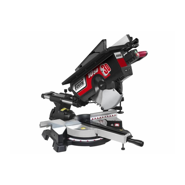
Femi
Femi 1050 3D User manual
Femi
Femi 787XL Specification sheet
Femi
Femi 785XL User manual
Femi
Femi 732 User manual
Femi
Femi NG120XL User manual
Femi
Femi 782 Specification sheet
Femi
Femi VB 28-191 User manual

Femi
Femi 2200 Specification sheet

Femi
Femi XXX Specification sheet

Femi
Femi N310DA DG User manual

Femi
Femi 999 Specification sheet

Femi
Femi NG 120 Specification sheet
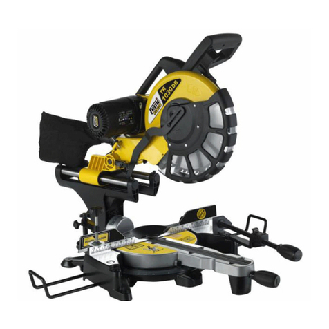
Femi
Femi TR 1030DB User manual

Femi
Femi NG 160 Specification sheet
Femi
Femi 280 Specification sheet
Femi
Femi TR 305-i User manual
