Femi 999 Specification sheet

ISTRUZIONI PER LUSO E MANUTENZIONE
INSTRUCTIONS FOR USE AND MAINTENANCE
GEBRAUCHSANLEITUNGEN UND WARTUNG
MODE DEMPLOI ET ENTRETIEN
INSTRUCCIONES PARA EL USO Y MANUTENCION
INSTRUÇÕES DE UTILIZAÇÃO
TRONCATRICE CIRCOLARE
MITRE-SAWS
KREISSÄGEN
SCIES A ONGLET
TRONZADORAS
SERROTE CIRCULAR
CERTIFICATA
CERTIFIED
GEPRÜFT
CERTIFIE
CERTIFICADA
CERTIFICADA
Art.
999
www.femi.it

ITALIANO (IT) ............................................................................................................... 1 ÷ 6
ENGLISH (EN) ............................................................................................................ 7 ÷ 12
DEUTSCH (DE) ........................................................................................................ 13 ÷ 18
FRANCAIS (FR) ....................................................................................................... 19 ÷ 24
ESPANOL (ES) ......................................................................................................... 25 ÷ 30
PORTUGUÊS (PT) ................................................................................................... 31 ÷ 36
01 07
02 08
03 09
04 10
05 11
06 12
2007 2010
2008 2011
2009 2012
Serie - Serial - Matrikel - Matricule - Matricula -
Matricula
Nr. .......................................................
DICHIARAZIONE DI CONFORMITÁ CE
DEL COSTRUTTORE FEMI S.p.A.
Via Salieri, 33-35 - 40024 Castel San Pietro Terme (BO) - ITAL
Tel. +39-051-941866 - Fax +39-051-6951332 - http://www.femi.it
Dichiara sotto la nostra esclusiva responsabilità che questa
macchina è conforme alle disposizioni della Direttiva Macchine 98/
37/CE ed è identico, in quanto incluso nell allegato IV della direttiva,
al macchinario oggetto della certificazione CE di tipo (vedi etichetta
riportata) rilasciata da ICE Istituto Certificazione Europea SpA,
organismo notificato n. 0303. E inoltre conforme alle disposizioni
delle seguenti altre direttive: 2006/95/CE, 200 /108/CE.
COMPLIANCE DECLARATION CE
OF THE BUILDER FEMI S.p.A.
Via Salieri, 33-35 - 40024 Castel San Pietro Terme (BO) - ITAL
Tel. +39-051-941866 - Fax +39-051-6951332 - http://www.femi.it
Declare under our sole responsibility that the machine,to which this
declaration relates, is in conformity with the regulations indicated in
Machinery Directive 98/37/CE and is identical, in that it is included
in appendix IV of the directive, to the machinery concerning CE
certification type (see relative label) issued by the ICE (Istituto
Certificazione Europea SpA), Notified Body no. 0303. Furthermore
it is also in conformity with the following standards: 2006/95/CE,
200 /108/CE.
CE KONFORMITATS ERKLARUNG
DES HERSTELLER FEMI S.p.A.
Via Salieri, 33-35 - 40024 Castel San Pietro Terme (BO) - ITAL
Tel. +39-051-941866 - Fax +39-051-6951332 - http://www.femi.it
Erklärt unter seiner alleinigen Verantwortung, dass diese Maschine
den Bestimmungen der Maschinenrichtlinie 98/37/EWG entspricht,
und, insofern eingeschlossen in Anhang IV der Richtlinie, identisch
mit der maschinellen Ausrüstung ist, die Gegenstand der EG-
Baumusterbescheinigung ist (siehe das abgebildete Etikett), die
vom ICE (Istituto Certificazione Europea SpA, anerkannte Prüfstelle
Nr. 0303) erlassen wurde. Sie entspricht ferner den Bestimmungen
der folgenden weiteren Richtlinien: 2006/95/EWG, 200 /108/EWG.
DECLARATION DE CONFORMITE CE DU CONSTRUCTEUR
FEMI S.p.A.
Via Salieri, 33-35 - 40024 Castel San Pietro Terme (BO) - ITAL
Tel. +39-051-941866 - Fax +39-051-6951332 - http://www.femi.it
Déclare, sous sa propre responsabilité, que cette machine est
conforme aux dispositions de la Directive Machines 98/37/CE et
est identique, car incluse dans lannexe IV de la directive, à la
machine objet de la certification CE de type (voir étiquette rapportée)
remise par ICE Istituto Certificazione Europea SpA, organisme
notifié n° 0303. En outre, elle est conforme aux dispositions des
autres directives suivantes: 2006/95/CE, 200 /108/CE.
DECLARATION DE CONFORMIDAD CE
DEL CONSTRUCTOR FEMI S.p.A.
Via Salieri, 33-35 - 40024 Castel San Pietro Terme (BO) - ITAL
Tel. +39-051-941866 - Fax +39-051-6951332 - http://www.femi.it
Declara bajo su exclusiva responsabilidad que esta máquina cumple
con lo dispuesto por la Directiva Máquinas 98/37/CE y es idéntica,
en cuanto máquina que figura en el anexo IV de la directiva, a la
máquina objeto de la certificación CE de tipo (véase etiqueta
ilustrada) otorgada por ICE Instituto de Certificación Europea SpA,
organismo notificado nº 0303.
Asimismo, cumple también con lo dispuesto por las siguientes
directivas: 2006/95/CE y 200 /108/CE.
DECLARAÇÃO DE CONFORMIDADE CE DO CONSTRUTTORE
FEMI S.p.A.
Via Salieri, 33-35 - 40024 Castel San Pietro Terme (BO) - ITAL
Tel. +39-051-941866 - Fax +39-051-6951332 - http://www.femi.it
Declaramos sob a nossa exclusiva responsabilidade que esta
máquina está em conformidade com as disposições da Directiva
Máquinas 98/37/CE e que é idêntica, porque contemplada no anexo
IV da directiva, ao maquinário objecto da certificação CE de tipo
(ver a etiqueta indicada) emitida por ICE Istituto Certificazione
Europea SpA, organismo notificado nº 0303. Está também em
conformidade com as disposições das seguintes directivas: 2006/
95/CE, 200 /108/CE.

1
IT
1 INTRODUZIONE ALL'USO
Prima di iniziare le lavorazioni con la Vostra troncatrice,
leggete attentamente questo manuale di istruzioni, allo scopo
di conoscere la macchina ed i suoi impieghi, e le eventuali
controindicazioni.
Conservate con cura questo manuale: esso fa parte
integrante della macchina, e ad esso dovrete sempre riferirvi
per eseguire al meglio e nelle massime condizioni di sicurezza
le operazioni che in esso sono descritte.
Il manuale và tenuto sempre insieme alla macchina, a
portata di mano per potere essere consultato ogni volta si
renda necessario.
Utilizzate la macchina solo ed esclusivamente per gli
impieghi di seguito specificati, usandola come
raccomandato in questo manuale, e non cercando in alcun
modo di manometterla o forzarla, o di usarla per scopi non
adatti.
1.1 COLLOCAZIONE IN CORRISPONDENZA DEI
PUNTI D'USO
on sottovalutate i richiami "ATTE ZIO E" e "CAUTELA"
riportati in questo manuale.
Al fine di attirare l'attenzione e dare messaggi di sicurezza
le operazioni pericolose sono precedute da simboli e note
che ne evidenziano la pericolosità e spiegano come
comportarsi per evitare il pericolo.
Questi simboli e note sono di tre categorie identificati nelle
parole:
ATTENZIONE: comportamenti rischiosi che
potrebbero provocare gravi lesioni.
CAUTELA: comportamenti che potrebbero causare
lesioni non gravi o danni alle cose.
NOTE: le note precedute da questo simbolo sono di
carattere tecnico e facilitano le operazioni.
1.2 DIMENSIONI DI INGOMBRO
Lunghezza 580mm-Larghezza 540 mm-Altezza 650 mm
Piano superiore ...................................... 475 x 325 mm *
* Dimensioni piano di lavoro ..................... 460 x 305 mm
Sporgenza massima lama piano superiore .......... 55 mm.
Massa ...................................................................... kg 18
1 INTRODUZIONE ALLUSO .................................... 1
2 INSTALLAZIONE ...................................................... 2
3 REGOLAZIONI ........................................................ 3
4 UTILIZZAZIONE ...................................................... 4
5 ACCESSORI ............................................................ 5
6 MANUTENZIONE ..................................................... 5
7 GUIDA ALLA LOCALIZZAZIONE DEI GUASTI ....... 6
INDICE 1.3 SICUREZZA E NORMATIVA
La macchina è progettata e costruita secondo le prescrizioni
imposte dalle vigenti Direttive Comunitarie: 8/37/CE -
2006/ 5/CE, 2004/108/CE.
La dichiarazione di conformità CE allegata, unita al marchio
CE posto sul prodotto, costituisce elemento fondamentale
e parte integrante della macchina: garantiscono la conformità
del prodotto alle Direttive di sicurezza sopra citate.
1.4 TIPO DI IMPIEGO E CONTROINDICAZIONI
La troncatrice circolare è stata progettata e realizzata con
l'impiego delle più avanzate tecnologie, ed è in grado di
soddisfare tutte le esigenze di taglio di legno, alluminio e
materie plastiche tipiche del professionista, dell'artigiano e
dell'hobbista ai massimi livelli.
USO CONSENTITO
Essa puó tagliare:
- LEG O DURO E TE ERO, AZIO ALE ED ESOTICO,
LU GO E TRAVERSO VE A
e con adeguati adattamenti (lama specifica e morsetti):
- MATERIE PLASTICHE
- ALLUMI IO E SUE LEGHE
USO NON CONSENTITO
on è adatta per il taglio di:
- MATERIALI FERROSI, ACCIAI E GHISE E DI
QUALSIASI ALTRO MATERIALE DIVERSO DA QUELLI
SPECIFICATI ELLUSO CO SE TITO, ED I
PARTICOLARE DI SOSTA ZE ALIME TARI.
- SEGA CIRCOLARE SE ZA PROTEZIO E LAMA.
1.5 NORME DI SICUREZZA GENERALI
Mantenete sempre pulita la zona di lavoro dai residui di
lavorazione.
on usate la macchina in luoghi molto umidi o con
presenza di liquidi infiammabili o di gas.
on usatela all'aperto, quando le condizioni generali
meteo ed ambiente non lo consentono (es. atmosfere
esplosive, durante un temporale o precipitazioni).
Vestitevi adeguatamente: evitate di indossare abiti con
maniche larghe od oggetti, come sciarpe, catene o
bracciali, che potrebbero essere agganciati dalle parti
in movimento.
Usate sempre i dispositivi personali di protezione:
occhiali antinfortunistici conformi alle norme, guanti di
dimensioni adatte a quelle della mano, cuffie o inserti
auricolari e cuffie per il contenimento dei capelli, se
necessario.
Fate attenzione al cavo di alimentazione: non usatelo
per sollevare la macchina o per staccare la spina dalla
presa, e salvaguardatelo da spigoli vivi, oli e zone con
elevate temperature.
Tenete lontano i bambini dallutensile: non lasciate che
si avvicinino e che vengano a contatto con esso.
Quando si renda necessario usare prolungamenti del
cavo di alimentazione, usate solo quelli di
tipo,omologato.
Salvaguardatevi dalelettrificazione: evitate contatti con
oggetti con messa a terra, come tubi, termosifoni e
frigoriferi.

2
IT
1.6 NORME DI SICUREZZA PER I RISCHI
RESIDUI
on forzate inutilmente la macchina: una pressione di
taglio eccessiva può provocare un rapido deterioramento
della lama ed un peggioramento delle prestazioni della
macchina in termini di finitura e di precisione di taglio.
el taglio dellalluminio e delle materie plastiche si
consiglia di utilizzare gli appositi morsetti: i pezzi oggetto
di taglio devono sempre essere tenuti fermamente nella
morsa.
Evitate partenze accidentali: non tenete premuto il
pulsante di marcia mentre inserite la spina nella presa di
corrente.
Usate gli utensili raccomandati in questo manuale, se
volete ottenere dalla vostra troncatrice le migliori
prestazioni.
Tenete sempre le mani lontane dalle zone di lavorazione
mentre la macchina è in movimento; prima di eseguire
qualsiasi operazione rilasciate il pulsante
nell'impugnatura, spegnendo la macchina e facendola
fermare.
1.7 INFORMAZIONI RELATIVE AL RUMORE E
VIBRAZIONI
Rumore
Livello sonoro postazione
operatore (a vuoto) ............................. Leq = 89,9 dB (A)
Livello sonoro postazione operatore
(a carico) ................................................ Leq 88,9 dB (A)
Condizioni delle prove a carico:
Taglio tavola in abete 0x30 alla velocità di 2850 giri/
min
Potenza Sonora (a vuoto) .................... Lwa 100,0 dB (A)
Potenza Sonora (a carico) .................... Lwa 102,5 dB (A)
Le rilevazioni sono state eseguite utilizzando la norma U I
E ISO 3746.
Vibrazioni
Il valore medio quadratico ponderato in frequenza, dell
accelerazione mano braccio, non supera i 2,5 m/sec2.
Le rilevazioni sono state eseguite utilizzando la norma U I
E ISO 5349-1 e 5349-2.
NOTE: Per il taglio dellalluminio è
indispensabile luso dei mezzi personali di
protezione delludito, come cuffie o inserti
auricolari. Luso di tali mezzi è consigliato per
tutti gli altri impieghi.
1.8 INFORMAZIONI SULLA COMPATIBILITA
ELETTROMAGNETICA
Le recenti ormative Europee sulla sicurezza, ed in
particolare la Direttiva 2004/108/CE, prescrivono che tutte
le apparecchiature siano dotate di dispositivi di schermatura
per i radiodisturbi sia da che verso lambiente esterno.
Questa macchina è conforme alle prescrizioni. Le prove
sono state eseguite secondo le orme EN 55014-1, EN
55014-2.
1. DESCRIZIONE DELLA MACCHINA (Fig.1)
La troncatrice circolare è composta da tre parti fondamentali:
il corpo centrale , comprendente il motore 6, che è collegato
alla base 3 tramite lo snodo 4 ed il supporto girevole 5, ed
il gruppo di lavoro superiore, comprendente il piano di lavoro
15, la squadra di appoggio 17 e la protezione mobile della
lama 16. La base 3 viene impiegata come appoggio quando
si devono eseguire operazioni di troncatura ed intestatura
nelle diverse angolazioni disponibili; il piano superiore viene
impiegato come appoggio quando si devono rifilare o
sezionare tavole di legno di grandi dimensioni, ed in
particolare nel taglio del legno lungo vena.
Legenda Fig. 1
1 - Impugnatura di comando
2 - Interruttore di marcia
3 - Base
4 - Snodo corpo/base
5 - Supporto girevole
6 - Motore
7 - Lama
8 - Leva sblocco graduazione
- Pulsante di sblocco discesa corpo
10 - Protezione fissa lama
11 - Protezione mobile lama
12 - Aste fermo barra
13 - Collettore scarico polvere
14 - Morsetti ferma pezzo (optional)
15 - Piano di lavoro superiore
16 - Protezione mobile superiore
17 - Squadra di appoggio
18 - Piedi di appoggio
1 - Perno di blocco
51 - Pulsante blocco interruttore
52 - Pulsante rilascio interruttore
2 INSTALLAZIONE
2.1 RIMOZIONE DELL'IMBALLO
Rimuovete la scatola che protegge la macchina durante il
trasporto, avendo cura di mantenerla intatta, nel caso
dobbiate spostare la troncatrice per lunghi tragitti o
immagazzinarla per lunghi periodi.
2.2 MOVIMENTAZIONE
Date le dimensioni ridotte ed il peso contenuto, la troncatrice
può essere comodamente movimentata anche da una sola
persona, azionando l'apposito blocco per il trasporto tramite
lo spinotto 1 e sollevando la macchina dall'impugnatura di
comando 1.
2.3 TRASPORTO
el caso si renda necessario trasportare la macchina,
rimettetela nella scatola originale nella quale era contenuta
al momento dell'acquisto, facendo attenzione ad inserirla
nella giusta posizione rispetto alle frecce presenti
sull'imballo. Prestate molta attenzione agli ideogrammi
stampati sulla scatola, che forniscono le indicazioni di
pallettizzazione e sovrapposizione di più scatole. Per quanto
possibile, è buona norma fissare il carico con corde o
cinghie di sicurezza, per evitare spostamenti e cadute del
carico durante il trasporto.

3
IT
La testa si arresterà automaticamente quando di volta in
volta l'indice 22 si troverà allineato alla corrispondente
posizione impressa sulla scala graduata del girevole.
Per tutte le posizioni intermedie, una volta allineato l'indice
con la posizione sulla targa, bloccate il supporto girevole
tramite le due manopole 20.
3.2 REGOLAZIONE DELL'ANGOLO DI TAGLIO-
INCLINAZIONE TESTA (Fig.5)
La testa della macchina può inclinarsi fino ad un massimo
di 45° verso sinistra. Sbloccate la manopola 24 (nella
parte posteriore della macchina) e inclinate la testa fino
allarresto sul fermo a 45°, già tarato al momento del
collaudo. Bloccate quindi di nuovo la testa mediante la
manopola 24. Per tutte le altre posizioni intermedie, fate
coincidere l'indice 25 posto sulla parte posteriore della
testa con la corrispondente posizione impressa sulla scala
graduata 23 dello snodo.
ATTENZIONE: Nel taglio a doppia inclinazione
(rotazione più inclinazione testa) tenere il pezzo
saldo alla macchina con la mano destra e guidare
la discesa della testa con la mano sinistra (Fig.
16).
3.3 REGOLAZIONE/MONTAGGIO DEL FERMO
BARRA (ACCESSORIO) (Fig. 6)
Se dovete effettuare più tagli di pezzi tutti della stessa
lunghezza, usate l'arresto barra, evitando così di rifare
tutte le volte la stessa misura.
Avvitate l'asta 26 nel foro della base e bloccatela con il
grano 27; allentate il volantino 28 e posizionate il fermo 2
alla distanza necessaria dalla lama; ribloccate il volantino
28.
3.4 REGOLAZIONE ALTEZZA PIANO SUPERIORE
(Fig. 7)
SOLO PER SEGA CIRCOLARE
ATTENZIONE: Lavorando sul piano superiore, è
necessario montare il carter di protezione
inferiore in dotazione.
Per montare il carter, con la testa sollevata, inseritelo
sugli appoggi angolari 30 della base, dopo di che abbassate
di nuovo la testa e bloccate il corpo in questa posizione
tramite il perno di bloccaggio 1 . Per regolare l'altezza del
piano superiore, in modo da effettuare il taglio dello
spessore desiderato, eseguite le seguenti operazioni:
allentate i due volantini 32;
avvicinate la squadra di appoggio 17 alla lama;
abbassate o alzate il piano tramite il pomolo 53,
leggendo contemporaneamente sulla targhetta graduata
33 l'altezza di taglio desiderata;
bloccate i volantini 32.
2.4 POSIZIONAMENTO/POSTO DI LAVORO (Fig.
2-3)
Posizionate la macchina su un banco oppure su un
basamento/piedistallo sufficientemente piano, in modo da
avere la migliore stabilità possibile. Per un eventuale
fissaggio utilizzare gli appositi fori previsti sulla base.
Per eseguire le lavorazioni tenendo conto dei criteri
ergonomici, l'altezza ideale del banco o del basamento
deve essere quella che vi consente di posizionare il piano
della base, oppure il piano di lavoro superiore, tra i 90 ed i
95 cm. da terra (vedi Fig. 2). Il posizionamento della
macchina sul posto di lavoro deve essere eseguito in
modo da avere almeno 80 cm di spazio circostante, in tutte
le direzioni, intorno alla macchina, per potere effettuare
con assoluta sicurezza e spazio di manovra sufficiente la
pulizia, la manutenzione e le regolazioni necessarie (vedi
Fig. 3).
CAUTELA: Abbiate cura di posizionare la
macchina in una zona di lavoro adeguata sia
come condizioni ambientali che come luminosità:
ricordate sempre che le condizioni generali
dell'ambiente di lavoro sono fondamentali nella
prevenzione degli infortuni.
2.5 COLLEGAMENTO ELETTRICO
Controllate che l'impianto rete sul quale inserite la macchina
sia collegato a terra come previsto dalle norme di sicurezza
vigenti, e che la presa di corrente sia in buono stato.
Si ricorda all'utilizzatore che a monte dell'impianto rete deve
essere presente una protezione magnetotermica atta a
salvaguardare tutti i conduttori dai corto circuiti e dai
sovraccarichi. Tale protezione dovrà essere scelta anche
in base alle caratteristiche elettriche della macchina riportate
sul motore
NOTE: L'impianto elettrico della vostra
troncatrice è dotato di relè di minima tensione,
che apre automaticamente il circuito quando la
tensione scende sotto un limite minimo stabilito,
e che impedisce il ripristino automatico della
condizione di funzionamento quando la tensione
ritorna ai livelli nominali previsti. Se la macchina
subisce un arresto involontario non allarmatevi,
ma controllate se effettivamente sia venuta a
mancare la tensione nell'impianto di rete.
3 REGOLAZIONI
ATTENZIONE: Tutte le operazioni di regolazione
illustrate nei paragrafi seguenti devono essere
effettuate con motore della macchina spento.
3.1 REGOLAZIONE DELL'ANGOLO DI TAGLIO-
ROTAZIONE TESTA (Fig. 4)
La troncatrice è in grado di effettuare tagli orientati sia
verso destra che verso sinistra. Le posizioni fisse già
tarate sono: 15°, 22° 30', 30° e 45°. Per ottenere queste
posizioni, allentate la manopola 20, sbloccate la testa della
macchina, spingendo verso il basso la leva 21, e fate
ruotare il supporto girevole tramite l'impugnatura 1.

4
IT
Lo spintore va impugnato nella parte A, mentre
la parte B, dotata di diversi gradini per
ladattamento a spessori differenti, deve essere
posta a contatto con il pezzo da tagliare come
mostrato in figura. Tramite lo spintore è possibile
spingere il pezzo da tagliare, guidandolo
contemporaneamente tramite lappoggio sulla
squadra C, e mantenendo sempre le mani distanti
dalla zona di taglio della lama.
Con motore spento, bloccate la testa della macchina
in posizione abbassata, tramite il perno di blocco 1 .
Regolate l'altezza del piano superiore in base all'altezza
di taglio voluta e la squadra di appoggio come descritto
al paragrafo REGOLAZIO I.
Controllate il corretto funzionamento della protezione
mobile superiore: dopo averla alzata leggermente, deve
ritornare nella posizione originale, coprendo
completamente la lama.
Azionate il motore come descritto al punto 4.1, e
bloccate linterruttore nella posizione di chiuso,
premendo il pulsante di blocco 51 situato nella zona
inferiore dellimpugnatura.
Posizionate la tavola da sezionare sul piano,
appoggiandola lateralmente sulla squadra, e fate
avanzare il pezzo da tagliare in modo regolare e senza
forzature verso la lama.
CAUTELA: Il pezzo da tagliare deve sempre essere
tenuto saldamente, avendo l'accortezza di
impugnarlo lontano dalla linea di taglio della
lama.
Per fermare la macchina, premete linterruttore di marcia
2, che sblocca automaticamente il pulsante di blocco 51.
4.3 MONTAGGIO E/O SOSTITUZIONE DELLA
LAMA (Fig. 12)
ATTENZIONE: Effettuate queste operazioni
solamente dopo avere fermato il motore della
macchina rilasciando il pulsante di marcia 2
dellinterruttore.
Sbloccate la protezione mobile 11, premendo il nottolino
40 e contemporaneamente sollevando la protezione, in
modo da scoprire la lama.
Alzate il piano superiore fino alla sua massima altezza.
Togliere il tappo di protezione dellalbero porta portalama
dal coperchio scatola elettronica.
Prendete le due chiavi esagonali mm. 6 in dotazione:
inseritene una nel terminale 41 dellalbero motore, laltra
nella vite di fissaggio della lama 42; a questo punto
svitate la vite,tenendo presente che la filettatura della
vite è sinistrorsa.
Togliete la flangia esterna 43, smontate la lama
sfilandola dalla parte inferiore della testa, e montate la
lama nuova.
Assicuratevi, mediante controllo a vista, di montare la
lama con la dentatura orientata nella direzione
evidenziata dalla freccia posta sulla stessa.
A questo punto, rimontate la flangia esterna 43,
riavvitate la vite 42 e serratela con forza mediante le
chiavi esagonali in dotazione.
Abbassare il piano superiore fino allaltezza desiderata
e inserire il tappo di protezione dellalbero portalama.
3.5 REGOLAZIONE DELLA SQUADRA DI
APPOGGIO (Fig.8)
SOLO PER SEGA CIRCOLARE
Per eseguire il taglio di tavole nella dimensione desiderata,
potete variare la distanza della squadra di appoggio 17 dalla
lama. Allentate il pomello 37 e fate scorrere la squadra 17
fino a raggiungere la misura prestabilita, leggibile sulle scale
graduate 38 del piano di lavoro. Infine serrate il pomello 37,
tenendo presente che la posizione individuata dalla squadra
sulle scale graduate, corrisponde alla distanza dalla
superficie di taglio della lama.
3.6 REGOLAZIONE CUNEO
Perchè il cuneo divisore sia nella posizione corretta, tenerlo
ad una distanza tra i 3 mm e gli 8 mm dal dente della lama.
el caso non fosse così, agire sulla vite di fissaggio al braccio
e portarlo alla distanza descritta in precedenza (Fig. 17).
4 UTILIZZAZIONE
Una volta eseguite tutte le procedure e le operazioni fin qui
descritte, potete iniziare le lavorazioni.
ATTENZIONE: Tenete sempre le mani lontane dalla
zona di taglio e non cercate in alcun modo di
raggiungerla durante le operazioni.
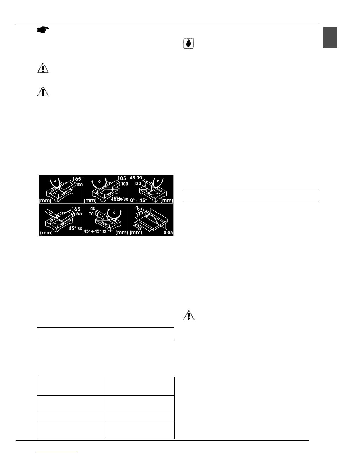
4.1 USO COME TRONCATRICE (taglio sul piano
inferiore) (Fig. 10)
Sbloccate la testa, svitando il perno di blocco 1 .
Sollevate la testa della macchina fino alla massima
escursione.
Assicurate saldamente il pezzo da tagliare contro gli
appoggi angolari 30 della base, con la mano sinistra, in
modo che non possa muoversi durante il taglio.
Ponete la mano destra sull'impugnatura 1, e premete il
pulsante in modo da sbloccare il movimento della
testa.
Azionate il motore, premendo prima il pulsante di rilascio
52, poi il pulsante di marcia 2 sullimpugnatura.
Fate scendere la testa, e mettete gradualmente a
contatto la lama con il pezzo da tagliare.
Eseguite il taglio completo del pezzo, e riportate la testa
nella posizione originale.
Spegnete il motore, rilasciando il pulsante 2.
4.2 USO COME SEGA CIRCOLARE (taglio sul
piano superiore) (Fig. 11)
ATTENZIONE: Lavorando sul piano superiore, è
necessario montare il carter di protezione
inferiore in dotazione.
ATTENZIONE: La macchina è dotata di spintore
di dimensioni e forma conformi a quelle prescritte
dalle norme di sicurezza (Fig. 15). Quando la
macchina viene usata come SEGA CIRCOLARE
(utilizzando per le lavorazioni il piano di lavoro
superiore ...) tale accessorio deve essere
OBBLIGATORIAMENTE utilizzato.

5
IT
4.5 BASE DI APPOGGIO SUPPLEMENTARE
Per aumentare la superficie di appoggio del pezzo nella
base, la vostra troncatrice è dotata di appoggio
supplementare. Con essa si riescono a compiere tutti i tipi
di taglio con la testa verticale (ES. 90°, 45° DX-SX, ecc.).
Per tutte le lavorazioni con la testa inclinata è necessario
allentare il pomello, sollevare la base di appoggio
supplementare fino a quando la borchietta a croce più
bassa non si sfili dal foro, ruotarla di 180°, incastrarla nel
foro posizionato nella parte opposto e restringere il pomello.
Una volta terminati i tagli con la testa inclinata si consiglia
di riposizionare la base di appoggio supplementare nella
condizione iniziale restringendo il pomello.
5 ACCESSORI
5.1 SCELTA DELLA LAMA
La troncatrice è dotata di serie di lama al WIDIA
(diametro 305 x foro 30 x spessore 2,5 mm),
Sono disponibili le seguenti lame:
5.2 MORSETTI (Fig.13) (OPTIONAL)
CAUTELA: Quando dovete tagliare barre o pezzi
di alluminio o di plastica, si consiglia di
utilizzare il morsetto per assicurare il pezzo agli
appoggi angolari, evitando così che si muova
durante il taglio causando inceppamenti che
potrebbero danneggiare il pezzo stesso e la lama.
Verificare sempre che il pressore del morsetto sia ben a
contatto con il pezzo da tagliare e che lo blocchi in modo
efficace sulla base.
5.3 ASPIRAZIONE DELLE POLVERI (Fig. 14)
(OPTIONAL)
La troncatrice è predisposta per il collegamento con un
aspiratore, o per il montaggio del sacchetto raccogli polvere,
tramite il collettore di scarico 13. Il tubo dell'aspiratore o la
manichetta del sacchetto devono essere fissati al collettore
tramite una fascetta. Vi raccomandiamo di svuotare
periodicamente il sacchetto o il contenitore dell'aspiratore,
e di pulire il filtro. La velocità di uscita dellaria creata
dallaspiratore deve essere almeno di 100 m3/h. Aspiratori
capaci di creare queste depressioni sono ad esempio quelli
di tipo bidone.
6 MANUTENZIONE
6.1 INTERVENTI DI MANUTENZIONE ORDINARIA
Le normali operazioni di manutenzione ordinaria, effettuabili
anche da personale non specializzato, sono tutte descritte
nei paragrafi precedenti e nel presente.
1. La troncatrice non ha bisogno di alcuna lubrificazione,
in quanto il taglio deve essere sempre effettuato a
secco (compreso quello dell'alluminio e delle leghe
leggere); tutti gli organi rotanti della macchina sono
autolubrificati.
2. Durante le operazioni di manutenzione, indossate per
quanto possibile i mezzi personali di protezione (occhiali
antinfortunistici e guanti)
3. Rimuovete i trucioli residui di lavorazione ogni qualvolta
si renda necessario, intervenendo nella zona di taglio e
sui piani di appoggio.
E' consigliato l'uso di un aspiratore o di un pennello.
ATTENZIONE: Non usate getti di aria compressa !!!
4. Verificate periodicamente le condizioni della lama: se
doveste riscontrare difficoltà nel taglio, fatela affilare
da personale specializzato, oppure sostituitela, se
dovesse presentarsene la necessità.
5. Verificare periodicamente che larresto della lama
avvenga entro 10 secondi dal rilascio del pulsante e
che la molla del braccio permetta al braccio di risalire
fino al fermo meccanico in un tempo non superiore ai
2 secondi se questo non avviene fate controllare la
vostra troncatrice da personale autorizzato.
6.2 ASSISTENZA
el caso sia necessario l'intervento di personale
specializzato per operazioni di manutenzione straordinaria,
oppure nel caso di riparazioni, sia in regime di garanzia che
successivamente, rivolgetevi sempre ad un centro di
assistenza autorizzato, oppure direttamente alla fabbrica,
se nella vostra zona non è presente il centro di assistenza.
NOTE:
La protezione mobile 11 ritornerà nella corretta
posizione automaticamente alla prima discesa
della testa della macchina, senza bisogno di
riposizionare il nottolino.
ATTENZIONE:
Montare tappo di protezione per evitare entrata
polveri.
ATTENZIONE
È assolutamente vietato montare lame che alla
vista risultino incrinate. Montare esclusivamente
lame a norma EN 847-1.
È assolutamente vietato utilizzare lame ad alta
velocità in acciaio.
Utilizzate sempre lame affilate e di dimensioni
idonee.
4.4 CAPACITA' DI TAGLIO
Le tabelle di seguito riportate specificano le capacità di
taglio a 0° e 45° ottenibili nelle normali condizioni di utilizzo
descritte in questo manuale.
Per legno nazionale ed
esotico di varie durezze
Per truciolari laminati fino a
spessore 30 mm
Per cornici
Per alluminio e materie
plastiche
Lama D.305 mm. 24÷48
Denti
Lama D.305 mm. 72 Denti
Lama D.305 mm. 96 Denti
per alluminio

6
IT
Ladeguata raccolta differenziata per lavvio successivo
dellapparecchiatura dismessa al riciclaggio, al
trattamento e allo smaltimento ambientalmente
compatibile contribuisce ad evitare possibili effetti
negativi sullambiente e sulla salute e favorisce il
reimpiego e/o riciclo dei materiali di cui è composta
lapparecchiatura.
ATTENZIONE!
Lo smaltimento abusivo del prodotto da parte
dellutente comporta lapplicazione delle
sanzioni amministrative previste dalla normativa
vigente.
6.3 SMALTIMENTO MACCHINA,
IMBALLAGGIO
INFORMAZIONE AGLI UTENTI
Ai sensi dellart. 13 del Decreto
Legislativo 25 luglio 2005, n. 151
Attuazione delle Direttive 2002/95/CE,
2002/96/CE e 2003/108/CE, relative alla
riduzione delluso di sostanze pericolose nelle
apparecchiature elettriche ed elettroniche, nonché allo
smaltimento dei rifiuti, si precisa quanto segue:
Il simbolo del cassonetto barrato riportato
sullapparecchiatura o sulla confezione indica che il
prodotto alla fine della propria vita utile deve essere
raccolto separatamente dagli altri rifiuti. L u t e n t e
dovrà, pertanto conferire lapparecchiatura giunta a fine
vita agli idonei centri di raccolta differenziata dei rifiuti
elettronici ed elettrotecnici, oppure riconsegnarla al
rivenditore al momento dellacquisto di una nuova
apparecchiatura di tipo equivalente, in ragione di uno a
uno.
Il motore non funziona
Il motore parte
lentamente o non
raggiunge la velocità di
funzionamento.
Eccessivo rumore del
motore.
Il motore non sviluppa la
piena potenza.
Il motore tende a
surriscaldare.
La sega cigola allavvio
Riduzione della capacità
di taglio.
La finitura del taglio risulta
grezza o ondulata.
Scheggiatura del pezzo
tagliato.
Motore, cavo rete o spina difettosi.
Fusibili bruciati.
Bassa tensione di alimentazione.
Avvolgimenti danneggiati.
Condensatore bruciato.
Avvolgimenti danneggiati.
Motore difettoso.
Circuiti dellimpianto rete
sovraccaricati da luci, servizi o altri
motori.
Il motore è sovraccaricato.
Raffreddamento del motore non
adeguato.
Cinghia di trasmissione poco tesa
o usurata
La lama è stata affilata molte volte
e si è ridotta di diametro.
La lama è consumata oppure non
ha la dentatura adatta allo spessore
del materiale che state tagliando.
La dentatura della lama non è
adatta al pezzo che state tagliando.
Fate controllare la macchina da personale
specializzato.
on cercate di riparare da soli il motore: potrebbe
essere pericoloso.
Controllate i fusibili e sostituiteli se necessario.
Richiedete un controllo della tensione disponibile
da parte dellEnte erogatore.
Fate controllare il motore della macchina da
personale specializzato.
Fate sostituire il condensatore da personale
specializzato.
Fate controllare il motore da personale specializzato.
on utilizzate servizi o altri motori sullo stesso
circuito al quale collegate la macchina.
Evitare di sovraccaricare il motore durante
loperazione di taglio. Rimuovere la polvere dal
motore per ottenere il corretto flusso dellaria di
refrigerazione.
Fate controllare la cinghia da personale autorizzato.
Intervenite sulla regolazione del fine corsa della
discesa della testa.
Fate affilare la lama da un centro di affilatura
specializzato.
Controllate se la dentatura che state usando è
giusta nel paragrafo SCELTA DELLA LAMA.
Controllate qualè la giusta dentatura da utilizzare
nel paragrafo SCELTA DELLA LAMA.
PROBLEMA PROBABILE CAUSA RIMEDIO SUGGERITO
7 GUIDA ALLA LOCALIZZAZIONE DEI GUASTI

7
EN
1 INTRODUCTION TO USE ...................................... 7
2 INSTALLATION ......................................................... 8
3 ADJUSTMENT ..........................................................
4 USE ........................................................................ 10
5 ACCESSORIES ...................................................... 11
6 MAINTENANCE ...................................................... 11
7 TROUBLESHOOTING ........................................... 12
1 INTRODUCTION TO USE
Before using your mitre-saw, please read this instruction
manual very carefully in order to become familiar with the
machine and its recommended use.
Do not lose this manual as it is an essential part of the
machine itself. We recommend you always refer to it in
order to operate the machine in the best and safest way
possible.
Keep the manual with the machine and handy at all times
to be consulted whenever necessary.
Use the machine exclusively for the uses specified below,
follow manual instructions carefully and never try to force
or to tamper with it, or to use it inappropriately.
1.1 SAFETY INFORMATION AND NOTES
Do not underestimate the symbols "HAZARD" and
"CAUTIO " in this manual.
Symbols and notes precede all hazardous operations both
to give safety messages and to draw the users' attention
to danger and also to outline the appropriate behaviour to
adopt to avoid such events.
The three symbols used and relative wording are the
following:
ATTENTION:
high risk behaviour which could be severely
harmful.
CAUTION: behaviour which could be
moderately harmful or damage objects.
NOTE: the notes preceded by this symbol are
of a technical nature and simplify use.
1.2 OVERALL DIMENSIONS
Lenght 580mm-Width 540 mm-Height 650 mm
Upper work surface ................................ 475 x 325 mm *
* Dimension work surface ........................ 460 x 305 mm
Upper work surface max protrusion of blade ....... 55 mm
Bulk ........................................................................ kg. 18
INDEX 1.3 SAFETY AND RULES
The machine was designed and built according to the
Community Directives in force: 8/37/CE, 2006/ 5/CE,
2004/108/CE.
The enclosed CE Declaration of conformity, togheter with
the CE mark on product, essentially comprise and are an
integral part of the machine: both guarantee product
conformity with the aforesaid safety Directives.
1.4 RECOMMENDED AND NOT RACCOMENDED
USE
The most advanced technologies have been used to design
and manufacture the mitre-saw. It is suitable to cut wood,
aluminium and plastics used by professionals, craftsmen
and expert hobbyists alike.
SUITABLE USE
To c ut :
HARD A D SOFT, DOMESTIC A D EXOTIC WOOD
BOTH LO GITUDI ALLY A D TRA SVERSALLY
and with appropriate adjustments (specific blade and
clamps):
PLASTICS
ALUMI IUM A D ALUMI IUM ALLOYS
UNSUITABLE USE
Do not cut:
FERROUS MATERIALS, STEEL A D CAST IRO OR
A Y OTHER MATERIAL OT ME TIO ED ABOVE A D
I PARTICULAR FOODSTUFFS.
CIRCULAR SAW WITHOUT PROTECTIO .
1.5 STANDARD SAFETY PROCEDURE
Remove all cuttings from the work surface ensuring it
is completely clean.
Use the machine in dry areas and away from
inflammable substances or gas.
Do not use the machine outdoors in adverse weather
or environmental conditions (explosive atmospheres,
storms or rain).
Wear appropriate clothing: do not wear loose-sleeved
garments or objects such as scarves, chains or
bracelets which may get caught in machine's moving
parts.
Always use personal protective gear: standard accident-
prevention goggles, well-fitting gloves, earphones or
earplugs and headgear to cover hair if necessary.
Handle the power supply cable with care: do not use it
to lift the machine or to pull the plug out of the socket.
Keep it away from cutting edges, oily patches and high
temperatures.
Keep the machine out of reach of children: do not allow
them to approach or touch the machine.
When in need, only use approved power supply cable
extensions.
Beware of electrification: avoid all contact with earthed
objects such as pipes, radiators and refrigerators.

8
EN
1.6 SAFETY PROCEDURE FOR FURTHER RISKS
Do not force the machine unnecessarily: excessive
cutting pressure may lead to rapid deterioration of the
blade and a decrease in performance in terms of finish
and cutting precision.
When cutting aluminium or plastics, it is advisable to
use the clamps designed for this purpose: all
workpieces must be clamped down firmly.
Avoid accidental starts: do not press the start button
while inserting the plug into the socket.
Always use the tools recommended in this manual to
obtain the best results from your cutting-off machine.
Always keep hands away from the work area when the
machine is running; before performing tasks of any
kind release the main switch button located on the
handgrip, thus disconnecting the machine.
Always keep hands away from the work area when the
machine is running; before performing tasks of any
kind release the main switch button located on the
handgrip, thus disconnecting the machine.
1.7 INFORMATION CONCERNING NOISE AND
VIBRATION LEVELS
Noise
oise level at the operators work
position (without load) ............................ Leq 89.9 dB (A)
oise level at the operators
work position (with load) ............................ Leq 88.9 dB(A)
Test conditions when working with load:
Cutting a deal plank ( 0x30 mm) at the speed of 2,850
rev/min
Sound power (without load) ................... Lwa 100.0 dB (A)
Sound power (with load) ........................ Lwa 102.5 dB (A)
The measurements were carried out in accordance with
standard U I E ISO 3746.
Vibration
Mean frequency-weighted hand - arm acceleration vibration
exposure does not exceed 2.5 m/s².
The measurements were carried out in accordance with
standards U I E ISO 5349-1 and 5349-2.
NOTE: When cutting aluminium the use of
protective earphones or ear plugs is absolutely
necessary. The use of this gear is also
recommended for all other uses.
1.8 INFORMATION ABOUT ELECTROMAGNETIC
COMPATIBILITY
The European regulations on safety and, in particular, the
2004/108/EEC contemplate that all the equipment be
equipped with shielding devices against radio interferences
both from and towards the outside. This machine is safe
and in compliance with the above regulations.
Tests were carried out according to Safety Standard EN
55014-1, EN 55014-2.
1. MACHINE DESCRIPTION (Fig. 1)
The mitre-saw machine consists of three basic parts: the
machine body complete with motor 6 which is integrated
into lower part 3 by means of the joint 4 and the swivel
support 5, and the upper work unit consisting of the work
table 15, the rest square 17 and the movable blade cover
16.
The base 3 is used as rest when cutting and butting
operations have to be carried out in the different available
angles; the upper table is used as rest when trimming or
sectioning wood tables of huge dimensions and, in particular,
when cutting wood along grain.
Legend Fig. 1
1 - Control handgrip
2 - Main switch start button
3 - Base
4 - Body/base swivel joint
5 - Rotating bearing
6 - Motor
7 - Blade
8 - Lever to unblock graduation
- Button to unblock body descent
10 - Permanent blade shield
11 - Movable blade shield
12 - Bar clamp shaft
13 - Dust exhaust manifold
14 - Workpiece clamps (optional)
15 - Upper work surface
16 - Movable upper safety guard
17 - Bearing bracket
18 - Support feet
1 - Transport locking pin
51 - Main switch locking device
52 - Main switch release device
2 INSTALLATION
2.1 REMOVAL OF PACKAGING
Remove the box used to protect the machine during
transportion and keep it intact for future transportation and
storage.
2.2 HANDLING
This mitre-saw is small and light and, therefore, can be
easily handled by one person alone by locking the
transportation block by means of the pin 1 and by lifting
the machine by means of the control handgrip 1.
2.3 TRANSPORTATION
To transport the machine, place it in the box it was in when
purchased. Ensure it is placed in the correct position indicated
by the arrows on the packaging.
Pay careful attention to the ideograms printed on the box
as they provide all necessary information for palletization
and stacking of boxes.
Tying the load down with ropes or safety belts is
recommended during transportation to stop the load from
sliding or falling.

9
EN
The head stops automatically each time the pointer 22 is
aligned with the corresponding position etched on the
graduated scale of the rotating plate.
For all intermediate positions, once the the index is in
alignment with the position on the plate, block the rotating
bearing by means of the two knobs 20.
3.2 ADJUSTMENT OF CUTTING ANGLE - HEAD
ANGLE (Fig. 5)
The machine head can be tilted to a maximum of 45° to the
left. Release the knob 24 (on the rear part of the machine)
and tilt the head until it comes to rest on the stopper at an
angle of 45° (already calibrated during testing). Retighten
the knob 24 to securely block the head in place. For all
other intermediate positions, align index 25 on the rear of
the head with the corresponding position marked on the
graduated scale 23 of the swivel joint (Fig. 16).
ATTENTION:
During double angle cutting (rotation plus head
tilting) hold the work piece securely to the
machine using the right hand and guide the
lowering of the head with the left hand (Fig. 16).
3.3 ADJUSTMENT/INSTALLATION OF BAR CLAMP
(ACCESSORY) (Fig. 6)
To cut work pieces of the same length, use the bar clamp
in order to avoid repeating the same measuring procedure
more than once.
Screw the bar 26 into the hole in the base and block it with
the dowel 27: loosen the handwheel 28 and position the
clamp 2 at the appropriate distance from the blade; then
tighten the handwheel 28.
3.4 ADJUSTMENT HEIGHT OF
UPPER WORK SURFACE (Fig. 7)
JUST FOR CIRCULAR SAW
ATTENTION: When working on the upper surface,
it is absolutely necessary to install the lower
safety guard supplied.
To install the safety guard with the head uplifted, place it
on the angular bearings 30 of the base. Then lower the
head and block the body in this position by means of the
block pin 1 .
To adjust the height of the upper work surface to obtain
desired cutting widths, follow the instructions below:
loosen the two handwheels 32;
move the bearing bracket 17 toward the blade;
lower or lift the work surface using knob 53,
simultaneously observing the desired cutting height on
the graduated plate 33;
tighten the handwheels 32;
2.4 POSITION/WORK STATION (Fig. 2-3)
Place the machine on a work bench or on a sufficiently flat
base/pedestal to ensure the best possible stability.
Should you wish to fix the machine in place, use the
special holes located on the base. These are available as
an optional.
Bearing in mind ergonomic criteria, the ideal height of the
bench or of the base should be such that the base surface
or the upper work surface is between 90 and 95 cm. from
the ground (see fig. 2).
Always ensure that there is at least 80 cm. of manoeuvring
space in all directions around the machine in order to
perform all necessary cleaning, maintenance and
adjustment operations safely with a sufficient amount of
space available (see fig. 3).
CAUTION: Ensure the machine is placed in a
suitable position both in terms of environmental
conditions and lighting.
Always bear in mind that general environmental
conditions are of fundamental importance to
prevent accidents.
2.5 ELECTRICAL CONNECTIONS
Check that the electrical system to which the machine is
connected is earthed in compliance with current safety
regulations and that the current socket is in perfect condition.
The electrical system must be fitted with a magnetothermal
protective device to safeguard all conductors from short
circuits and overload.
The selection of this device should be in line with the
following electrical specifications of the machine stated
on the motor.
NOTE: Your mitre-saws electrical system is
equipped with an undervoltage relay which
automatically opens the circuit when the voltage
falls below a minimum pre-established limit and
which prevents the self-reset of machine
functions when voltage returns to normal levels.
If the machine stops involutarily, do not be
allarmed. Make sure that there has not been a
voltage failure in the electrical system.
3 ADJUSTING (F g. 4-5-6-7-8)
ATTENTION: All the adjustment procedures
illustrated below must be performed when the
machine's engine is off.
3.1 ADJUSTMENT OF CUTTING ANGLE-HEAD
ROTATION (Fig. 4)
This mitre-saw can cut both to the left and to the right.
The pre-set positions are: 15° - 22°30' - 30° and 45°.
To position the machine as above, loosen knob 20, release
the machine head by pushing the lever 21 downwards and
rotate the rotary support by using the handgrip 1.

10
EN
Hold pusher from side A while side B, equipped
with different steps to match different thickness
sizes, must be put in contact with the piece to be
cut as shown in the figure. The piece to be cut
can be pushed by means of the pusher which
simultaneously drives and rest it on square C
thus enabling to keep hands away from the blade
cutting area.
When the motor is off, lower the machine head and
block it by means of the block pin 1 .
Adjust the height of the upper work surface according
to the cutting height desired and adjust the bearing
bracket as described in the paragraph "ADJUSTME TS".
Check that the removable upper shield is not faulty:
after having lifted it slightly, it must return to its orginal
position, covering the blade completely.
Start the motor as described at point 4.1, and lock the
main switch in O position by means of the locking
device 51 in the lower zone of the handgrip.
Place the workpiece to be cut on the work surface,
placing it laterally against the bracket and then move
the workpiece slowly and gradually towards the blade.
CAUTION: The workpiece must always be held
firmly, paying attention not to hold it near the
cutting area.
to turn off the machine, push the start button 2 of the
main switch, automatically release the locking device
51.
4.3 INSTALLATION AND/OR REPLACEMENT OF
THE BLADE (Fig. 12)
ATTENTION: This procedure must be carried out
only after having turned off the machine's motor
by by release the main switch button 2.
Release the movable shield 11 by pressing the pawl 40
and simultaneously raising the shield so as to uncover
the blade.
Raise the upper surface as high as possible.
Remove the protection plug of the blade-holding shaft
from the cover of the electronic box.
Use the two Allen wrenches supplied: insert the one for
6 mm. socket-head screws in the terminal 41 of the
driving shaft and the one for 8 mm. socket-head screws
in the blade's fixing screw 42; then loosen the screw,
taking in mind that the screw thread is left-handed.
Remove the external flange 43, remove the blade by
sliding it out from the lower part of the head and install
a new blade.
Ensure that the blade's teeth are oriented in the direction
of the arrow on the blade itself.
Then, remount the outer flange 43, tighten the screw
42 firmly, using the Allen wrenches supplied.
- Lower the upper surface to the required height and
insert the protection plug of the blade-holding shaft.
NOTE:
The movable shield 11 will return to the correct
position automatically when the machine head
is lowered, without having to reposition the
pawl.
3.5 ADJUSTMENT OF BEARING BRACKET (Fig.
8)
JUST FOR CIRCULAR SAW
For cutting planks of the required size, it is possible to
adjust the distance of the support square 17 from the
blade. Loosen the knob 37 and slide the square 17, until the
set measurement has been reached (this can be read on
the graduated index 38 found on the worktop). Finally
retighten the knob 37 bearing in mind that the position
indicated by the square on the index corresponds to the
actual distance from the cutting surface of the blade.
3.6 WEDGE REGULATION
To ensure the dividing wedge is in the correct position,
keep it at a distance of between 3mm - 8mm from the
tooth of the blade. Should this not be the case, loosen the
screw which holds it attached to the arm and move it to the
aforementioned distance (Fig. 17).
4 USE
After having performed all the above procedures and
operations, you may begin cutting.
ATTENTION: Always keep hands away from the
cutting area and do not try to approach it when
the machine is running.
4.1 USE AS A CUTTING-OFF MACHINE (cutting
on the lower work surface) (Fig.10)
Release the head, by unscrew the block pin 1 .
Raise the machine head as far as possible.
Secure the workpiece firmly against the angular bearings
30 of the base with your left hand, thus ensuring
absolute immobility during cutting.
Put your right hand on the handgrip 1 and press the
button in order to release the head.
Actuate the motor by pressing first the main switch
release device 52 and then the main switch start button
2 on the handgrip.
Lower the head and gradually bring the blade into contact
with the workpiece.
Complete cutting and raise the head to its original
position.
Turn off the motor by release the main switch button 2.
4.2 USE AS A CIRCULAR SAW
(cutting on the upper work surface) (Fig. 11)
ATTENTION: When working on the upper surface,
it is absolutely necessary to install the lower
safety guard supplied.
ATTENTION: The machine is equipped with a
pusher the dimensions and shape of which are
in compliance with the Safety Standards (Fig.
15). When the machine is used as DISK SAW
(thus using the upper table for the machining
operations), such fitting MUST absolutely be used.

11
EN
Blade D.305 mm. 48 Teeth
Blade D.305 mm. 72 Teeth
Blade D.305 mm. 96 Teeth
Blade D.305mm. 96 Teeth
for alluminium
To cut domestic and exotic,
hard and soft
To cut chipboards and
laminates to a maximum 30
mm
To cut frames
To cut alluminium and
plastics
ATTENTION:
Mount the protection plug to prevent dust from
entering.
ATTENTION:
Never install blades which appear to be
cracked. Only install blades which comply with
standard EN 847-1.
Using high speed blades in stainless steel is
strictly forbidden
Always use sharp blades of suitable dimensions
4.4 CUTTING CAPACITY
The following tables specifies the cutting capacity at 0°
and 45° which may be achieved under the normal conditions
of use illustrated in this manual.
5.2 CLAMPS (Fig. 13) (OPTIONAL)
CAUTION: When cutting bars or pieces of
aluminium or plastic, use of the clamp is
advisable to hold the piece firmly against the
angular bearings, thus avoiding movement
during cutting and, therefore, jams which could
damage both the workpiece and the blade.
Always check that the clamp jaw makes perfect contact
with the piece to be cut and that it effectively holds it in
position at the base.
5.3 SUCTION OF DUST RESIDUES (Fig.14)
(OPTIONAL)
The mitre-saw can be connected to an aspirator or a dust
collection bag can be mounted by means of the exhaust
manifold 13.
The aspirator pipe or the bag sleeve must be secured to
the manifold by means of a band. Users are reminded to
empty the bag or aspirator container and to clean the filter
regularly.
The air output speed must be equivalent to at least 100
m3/h.
For example, "dustbin" type aspirators are suitable.
6 MAINTENANCE
6.1 REGULAR MAINTENANCE
The regular maintenance decribed above and in the
paragraph below can be carried out by unskilled personnel.
1. Do not oil the mitre-saw, cause cutting must be carried
out in dry conditions (including the cutting of aluminium
and aluminium alloys); all rotating parts are self-
lubricating.
2. During maintenance, wear protective gear if possible
(accident-prevention goggles and gloves).
3. Remove cuttings when necessary both from the cutting
area, work surfaces and support bases.
Use of an aspirator or brush is recommended.
ATTENTION: Do not use compressed air jets!
4. Regularly check blade conditions: if difficulties should
arise during cutting, have it sharpened by skilled
personnel or replace it if necessary.
5. Periodically, check that the blade comes to a complete
standstill within 10 seconds of releasing the button,
and that the arms spring allows the arm to return back
up to its mechanical stop within 2 seconds; in the
event of either of these test returning a negative
outcome, get your machine serviced by an authorized
technician.
6.2 ASSISTENCE
When in need of skilled personnel for special maintenance,
or for repairs, both during and following the guarantee
period, always apply to authorized centres for assistance
or directly to the manufacturer if there is no authorized
centre in your area.
4.5 SUPPLEMENTARY SUPPORT BASE
Your cutting-off machine is fitted with a supplementary
support base to increase the supporting surface of the
workpiece in the base. All types of cuts may be carried out
with it, with the vertical head (e.g.: 90°, 45° RH-LH etc.).
To carry out work with head tilting, proceed as follows:
loosen the knob, raise the supplementary support plate
until the lowest internal guide pin has been lifted out of the
hole, rotate it through 180°, fix it in place in the hole located
on the opposite side and retighten the knob. Once cutting
with head tilting has been completed, it is advisable to
reposition the supplementary support table back in its original
position, not forgetting to tighten the knob.
5 ACCESSORIES
5.1 SELECTION OF THE BLADE
The mitre-saw is fitted with a WIDIA blade (305 diameter
x 30 hole x 2,5 thickness mm. ),
The following blades are available:

12
EN
The user must consign the unwanted appliance to an
authorized differentiated waste disposal centre for
electrical and electronic goods, or alternatively, hand it
over to the relative dealer on purchasing a new appliance
of the same type on the basis of a one to one ratio.
Differentiated disposal, to enable possible recycling or
environmentally compatible elimination of the appliance,
helps to limit undesirable effects on health and the
environment and promotes the reuse and/or recycling
of the materials which went into making up the appliance.
ATTENTION!
Sanctions, in accordance with the relative
legislation in force in the country of use, will be
imposed on the user if the appliance is disposed
of illegally.
6.3 DISPOSAL OF THE
MACHINE AND PACKAGING
INFORMATION FOR USERS
In accordance with art. 13 of Legislative
Decree 25th July 2005, no. 151
Implementation of Directives 2002/95/EEC, 2002/96/EEC
and 2003/108/EEC, relative to reducing the use of
hazardous substances in electrical and electronic
appliances and the disposal of waste, please take note of
the following:
The crossed out wheelie bin symbol found on the
appliance or on the packaging, indicates that the product
must be disposed of separately from ordinary household
waste when it reaches the end of its working life.
The motor does not run
The motor starts slowly
and does not reach
running speed
Excessive motor noise
The motor does not reach
full power
The motor tends to
overheat
The saw creaks at startup
Decrease in cutting
capacity
The cutting finish is
irregular or uneven
Flaking of the workpiece
Faulty motor, power supply cable
or plug.
Burned out fuses
Low power supply voltage.
Damaged windings.
Burned out capacitor
Damaged windings.
Faulty motor
Overloaded circuit due to lighting,
utilities or other motors
Overloaded motor.
Insufficient motor cooling
The drive belt is not taut enought
orn worn out.
The blade has been repeatedly
sharpened and its diameter has
decreased
The blade is worn out or the teeth
are not suited to the thickness of
the material being cut
The blades teeth are not suited to
the workpiece
Have the machine checked by skilled personnel.
Do not try to repair the machine yourselves as it
may be dangerous.
Check the fuses and replace them if necessary.
Ask for the Electricity Board to check the voltage
available.
Have the machine motor checked by skilled
personnel.
Have the capacitor replaced by skilled personnel.
Have the motor checked by skilled personnel
Do not use other utilities or motors on the circuit to
which the cutting-off machine is connected
Avoid overloading the motor during cutting. Remove
dust from the motor in order to allow adequate
cooling.
Have the belt checked by authorized personnel.
Adjust the limit switch for the lowering of the head
Have the blade sharpened by skilled personnel.
Check that the blade being used is appropriate by
refering to the paragraph SELECTIO OF THE
BLADE.
Check the appropriate teeth to use by refering to
the paragraph SELECTIO OF THE BLADE
PROBLEMS CAUSES SOLUTIONS SUGGESTED
7 TROUBLESHOOTING

13
DE
1.3 SICHERHEIT UND NORMEN
Die Maschine wurde so konzipiert und gebaut, daß sie den
Anforderungen der gültigen EG Richtlinien entspricht: 8/
37/EWG - 2006/ 5/EWG, 2004/108/EWG. Die beiliegende
EG Konformitätserklärung ist, zusammen mit dem auf dem
Produkt angebrachten CE Kennzeichen, ein grundlegendes
Element und ein wesentlicher Teil der Maschine: sie ist eine
Garantie, daß das Produkt den o. g. Sicherheitsrichtlinien
entspricht.
1.4 ALLGEMEINE SICHERVORSCHRIFTEN
Die Kreissäge wurde unter Verwendung von modernsten
technologischen Mitteln entwickelt und hergestellt. Sie
entspricht allen einschlägigen Anforderungen, die
Facharbeiter, Handwerker, sowie erstklassige Heimwerker
beim Holz-, Aluminium- und Plastikmaterialschneiden stellen.
VORGESEHENE VERWENDUNGSMÖGLICHKEITEN
Die Maschine schneidet:
HARTES U D WEICHES HOLZ I LÄ DISCHER
ODER EXOTISCHER HERKU FT, LÄ GS U D QUER
DURCH DIE MASERU G
unter der Voraussetzung daß die entsprechenden Teile
richtig eingesetzt werden (spezielles Sägeblatt und Klemmen:
PLASTIKMATERIAL
ALUMI IUM U D ALUMI IUMLEGIERU GE
NICHT VORGESEHENE
VERWENDUNGSMÖGLICHKEITEN
Die Maschine eignet sich nicht für:
EISE MATERIALIE , STAHL U D GUSSEISE ,
SOWIE ALLE A DERE MATERIALSORTE , DIE
ICHT AUFGEFÜHRT WERDE , VOR ALLEM
LEBE SMITTEL.
KREISSÄGE OH E SCHUTZ.
1.5 ALLGEMEINE SICHERHEITSVORSCHRIFTEN
Die Maschine darf nicht an sehr feuchten Orten oder
wenn entzündbare Flüssigkeiten oder Gase vorhanden
sind verwendet werden.
ie im Freien verwenden, wenn die allgemeinen Wetter-
und Umweltbedingungen dies nicht zulassen (z.B.:
explosive Atmosphären, während eines Gewitters oder
bei Regen).
Kleiden sie sich entsprechend: Tragen Sie keine breiten
Ärmel, Halstücher, Krawatten, Ketten oder Armreife, die
die Maschinenteile in ihrer Bewegung erfassen könnten.
Verwenden Sie stets Ihre persönlichen
Sicherheitsvorrichtungen: vorschriftsgemäße
Schutzbrille, Handschuhe in der richtigen Größe,
äußeren oder inneren Ohrenschutz, falls notwendig eine
Haube, die die Haare bedeckt.
Achten Sie auf das Stromkabel: es darf nie zum Anheben
der Maschine oder zum Entfernen des Steckers gezogen
werden, schützen Sie es vor scharfen Kanten, Öl und
Überhitzung.
Erlauben Sie nicht, daß Kinder sich der Maschine nähern
oder diese sogar anfassen.
Falls Verlängerungskabel notwendig sind, verwenden
Sie bitte nur geprüfte Artikel.
Schützen Sie sich vor Elektroschocks: vermeiden Sie
Kontakte mit geerdeten Gegenstände wie Röhren,
Heizkörper und Kühlschränke.
1 EINFÜHRUNG IN DIE BEDIENUNG
Bevor Sie mit Ihrer Kreissäge zu arbeiten beginnen, lesen
Sie bitte dieses Handbuch aufmerksam durch, bis Sie die
Maschine und ihre Verwendungsmöglichkeiten kennen und
wissen, für welche Anwendungsbereiche sie eventuell nicht
geeignet ist. Bewahren Sie dieses Handbuch sorgfältig
auf, es gehört zur Maschine und soll regelmäßig konsultiert
werden, damit die Operationen, die darin beschrieben werden,
bestmöglich und unter Einhaltung der
Sicherheitsbedingungen ausgeführt werden können. Das
Handbuch muß immer in der ähe der Maschine sein,
damit es im Bedarfsfalle gleich zum achschlagen bereit
ist. Benützen Sie die Maschine immer nur für die
Verwendungszwecke, die nachfolgend aufgeführt werden,
und zwar so, wie im Handbuch angegeben; versuchen Sie
keinesfalls, sie zu verändern, aufzubrechen oder für nicht
vorgesehene Verwendungszwecke zu benützen.
1.1 AUFSTELLUNG ENTSPRECHEND
DE A WE DU GSPU KTE
Unterschätzen Sie die Anweisungen "ACHTU G !" und
"VORSICHT!" in diesem Handbuch nie. Spezielle Symbole
und Hinweise sollen Ihre Aufmerksamkeit auf sich ziehen
und Sicherheitsanweisungen über gefährliche Operationen
geben. Daraus ersehen sie, wie gefährlich gewisse
Situationen sind und erfahren, wie Sie sich verhalten
müssen, damit jede Gefahr ausgeschlossen wird. Diese
Symbole und Hinweise sind wie folgt in drei Kategorien
aufgeteilt:
ACHTUNG: gefährliche Verhaltensweisen können
zu schweren Verletzungen führen.
VORSICHT: falsche Verhaltensweisen können zu
mittelschweren Verletzungen oder Sachschäden
führen.
MERKE: erscheint dieses Symbol vor einer
Erklärung, bedeutet dies, daß sie technischer Art ist
und die Operation erleichtern hilft.
1.2 PLATZBEDARF
Länge 580 mm - Breite 540 mm - Höhe 650 mm
Obere Fläche .......................................... 475 x 325 mm *
* Abmessungen Arbeitsfläsche ................ 460 x 305 mm
Sägeblatt ragt höchstens ...................................... 55 mm
Masse ...................................................................... kg 18
1 EINFÜHRUNG ................................................... 13
2 INSTALLIEREN .................................................. 14
3 EINSTELLUNGEN ............................................. 15
4 GEBRAUCH ....................................................... 16
5 MASCHINENTEILE ............................................ 17
6 WARTUNG ......................................................... 17
7 STÖRUNGSSUCHE UND - BEHEBUNG ......... 18
INHALT

14
DE
1.6 SICHERHEITSVORSCHRIFTEN FÜR
WEITERE RISIKEN
Forcieren Sie die Maschine nicht unnötig: zu starker
Druck beim Sägen beschädigt das Sägeblatt schnell,
was zu einer Leistungsverminderung der Maschine bei
der Verarbeitung und in der Schnittgenauigkeit führt.
Beim Schneiden von Aluminium und Kunststoffen
sollten stets die hierfür vorgesehenen Einspannungen
verwendet werden: die Teile, die gesägt werden sollen,
müssen immer zwischen den Klemmen fixiert werden.
Vermeiden Sie zufällige Inbetriebsetzungen der
Maschine: beim Einführen des Steckers in die Steckdose
darf die Betriebstaste nicht gedrückt werden.
Verwenden Sie das Werkzeug, das in diesem Handbuch
empfohlen wird. So erreichen Sie, daß Ihre Kreissäge
optimale Leistungen erbringt.
Die Hände dürfen nie in die Verarbeitungszone
gelangen, wenn die Maschine in Betrieb ist. Bevor Sie
irgendwelche Operationen vornehmen, lassen Sie die
Handgriffstaste und schalten Sie die maschine aus.
1.7 INFORMATIONEN ÜBER LÄRMAUFKOMMEN
UND VIBRATIONEN
Lärm
Geräuschpegel am Bedienerplatz
(Leerbetrieb) ............................................. Leq 89,9 dB (A)
Geräuschpegel am Bedienerplatz
(Lastbetrieb) ............................................. Leq 88,9 dB (A)
Prüfungsbedingungen bei Lastbetrieb:
Schnitt eines Tannenholzbretts 0x30 bei einer
Geschwindigkeit von 2850 U/min
Schallleistung (Leerbetrieb) ................... Lwa 100,0 dB (A)
Schallleistung (Lastbetrieb) ................... Lwa 102,5 dB (A)
Die Messungen wurden gemäß U I E ISO 3746
durchgeführt.
Vibrationen
Das frequenzbewertete quadratische Mittel der
Beschleunigung Hand-Arm übersteigt nicht 2,5 m/Sek2.
Die Messungen wurden gemäß U I E ISO 5349-1 und
5349-2 durchgeführt.
MERKE: Beim Schneiden von Aluminium muss
der Arbeiter unbedingt seinen persönlichen
Ohrenschutz tragen (Ohrenklappen oder innerlich
getragener Gehörschutz). Der Einsatz dieser Mittel
ist für alle anderen Verwendungszwecke empfohlen.
1.8 INFORMATIONEN ÜBER DIE
ELEKTROMAGNETISCHE
VERTRÄGLICHKEIT
Die neuesten Europäischen Sicherheitsbestimmungen und
insbesondere die Richtlinie 2004/108/EU schreiben vor,
dass alle Apparate mit Schutzeinrichtungen gegen
Funkstörungen von und in die Außenumgebung ausgestattet
sein müssen. Diese Maschine ist mit den folgenden ormen
konform: Die Prüfungen wurden gemäß den ormen EN
55014-1, EN 55014-2 vorgenommen.
1. BESCHREIBUNG DER MASCHINE (Abb. 1)
Die drei wichtigsten Teile der Kreissäge sind: das
Zentralgehäuse mit dem Motor 6, das durch das Gelenk 4
und die drehbare Halterung 5 an den Sockel 3
angeschlossen ist, die obere Arbeitsgruppe mit der
Arbeitsfläche 15, dem Tragwinkel 17 und dem beweglichen
Sägeblattschutz 16. Der Sockel 3 dient als Stütze, wenn
Trenn- und Stumpfstoßarbeiten in den verschiedenen
vorgesehenen Winkelstellungen vorgenommen werden
sollen: die obere Fläche wird als Stützfläche benützt, wenn
große Holzplatten beschnitten oder abgetrennt werden, vor
allem, wenn Holz in der Richtung der Maserung gesägt wird.
Legende Abb. 1
1 - Steuergriff
2 - Starttaste
3 - Sockel
4 - Gelenk Gehäuse/sockel
5 - Drehbare Halterung
6 - Motor
7 - Sägeblatt
8 - Freigabehebel Gradeinteilung
- Freigabetaste Gehäusesenkung
10 - Sägeblattschutz, Unbeweglich
11 - Sägeblattschutz, Beweglich
12 - Sperrstangen Für Den Stab
13 - Auffangbecken Für Sägemehl
14 - Fixierungsklemmen (optional)
15 - Obere Arbeitsfläche
16 - Oberer Beweglicher Schutz
17 - Tragwinkel
18 - Stützfüße
1 - Transportblockstift
51 - Schalterblocktaste
52 - Schalterlassentaste
2 INSTALLIEREN
2.1 ENTFERNUNG DER VERPACKUNG
ehmen Sie die Maschine aus ihrer Schachtel, die sie
während des Transports geschützt hat, ohne diese zu
beschädigen, denn sie könnte später wieder nützlich sein,
bei einem längeren Transport der Kreissäge oder einer
langfristigen Lagerung.
2.2 VERSCHIEBUNG
Da die Kreissäge relativ klein und leicht ist, kann ihr Standort
leicht verändert werden, auch von einer einzigen Person.
Es genügt, durch Einwirkung auf den Bolzen 1 das
Transportgesperre freizugeben und die Maschine mit dem
Steuergriff 1 hochzuheben.
2.3 TRANSPORT
Falls die Maschine transportiert werden muß, stellen Sie
sie in ihre Originalverpackung, in der sie geliefert wurde,
und passen dabei auf, daß sie in der richtigen Position
eingeführt wird (siehe Pfeile auf der Schachtel). Beachten
Sie bitte die Ideogramme auf der Verpakkung genau, denn
sie zeigen, wieviele Schachteln auf Pallets gepackt oder
übereinander gestapelt werden können. Wenn möglich, soll
die Ladung mit Seilen oder Sicherheitsriemen fixiert werden,
damit es während des Transports nicht zu Verschiebungen
kommt oder Teile der Ladung sogar herausfallen.

15
DE
2.4 POSITIONIERUNG/ARBEITSPLATZ (Abb. 2-3)
Positionieren Sie die Maschine auf eine Arbeitsbank oder
auf einen flachen Sockel, damit das Gerät so stabil wie
möglich steht. - Zum Befestigen die hierfür
vorgesehenen Löcher im Sockel verwenden. Bei der Arbeit
mit der Maschine müssen die ergonomischen Faktoren
berücksichtigt werden; die ideale Höhe des Arbeitstisches
oder des Sockels wird erreicht, wenn die Grundfläche oder
die obere Arbeitsfläche 90 bis 95 cm über dem Boden liegt
(siehe Abb. 2). Die Positionierung der Maschine muß so
erfolgen, daß sie mindestens 80 cm freien Raum um sich
herum hat, und zwar in allen Richtungen, damit die Reinigungs-
und Instandhaltungsarbeiten, sowie die notwendigen
Einstellungen unter Einhaltung der Sicherheitsbedingungen
und mit genügend Bewegungsraum erfolgen können (Abb. 3).
VORSICHT : Stellen Sie die Maschine in einer
Zone auf, die in bezug auf die
Umweltbedingungen und die Beleuchtung
geeignet ist. Vergessen Sie nie, daß die
allgemeinen Umweltbedingungen bei der Arbeit
eine extrem wichtige Rolle bei der
Unfallverhütung spielen.
2.5 ANSCHLUSS AN DAS STROMNETZ
Kontrollieren Sie, ob die etzanlage, an die Sie die Maschine
anschließen, entsprechend den gültigen ormen geerdet ist
und ob die Steckdose in gutem Zustand ist. Wir möchten Sie
daran erinnern, daß der etzanlage eine magnetothermische
Schutzvorrichtung vorgeschaltet sein muß, die alle Leitungen
vor Kurzschlüssen und Überlastungen schützt. Diese
Schutzvorrichtung kann auch aufgrund der nachfolgend
aufgelisteten elektrischen Eigenschaften der Maschine am
motor angegeben.
MERKE: Die elektrische Anlage Ihrer Kreissäge
ist mit einem Unterspannungsrelais versehen,
das automatisch den Stromkreis öffnet, wenn
die Spannung unter den vorbestimmten
Minimalwert sinkt, und verhindert, daß der
Betrieb der Maschine automatisch wieder
aufgenommen wird, wenn die Spannung wieder
Normalwerte erreicht. Falls es aus Versehen zu
einem Maschinenstop kommt, ist dies nicht
schlimm. Kontrollieren Sie, ob wirklich eine
Spannungssenkung in der Netzanlage
stattgefunden hat.
3 EINSTELLUNGEN
ACHTUNG: Bevor Sie eine der in den folgenden
Abschnitten beschriebenen Einstellungsarbeiten
vornehmen, kontrollieren Sie bitte, ob der Motor
der Maschine ausgeschaltet ist.
3.1 EINSTELLUNG DES SCHNITTWINKELS UND
DER KOPFDREHUNG (Abb. 4)
Die Kreissäge kann nach links oder rechts gerichtet
schneiden. Die bereits voreingegebenen Positionen sind:
15°, 22°30', 30° und 45°. Zum Einstellen dieser Positionen
den Handgriff 20 lockern, den Maschinenkopf freigeben,
den Hebel 21 nach unten drücken und die drehbare
Halterung mit dem Griff 1 drehen lassen.
Der Kopf hält automatisch an, wenn sich der Zeiger 22 auf
Höhe der jeweiligen Position auf der Strichskala der
drehbaren Halterung befindet.
Für alle Zwischenpositionen muß die drehbare Halterung
mit den zwei Handgriffen 20 blockiert werden, wenn der
Zeiger auf der gewünschten Position des Skalenschildes
steht.
3.2 EINSTELLUNG DES SCHNITTWINKELS UND
DER KOPFNEIGUNG (Abb. 5)
Der Maschinenkopf kann sich bis zu einem Winkel von 45°
nach links neigen. Entriegeln Sie den Griff 24 (im hinteren
Teil der Maschine) und neigen Sie den Kopf, bis dieser bei
45° einrastet (bei Abnahme geeicht). Dann blockieren Sie
den Kopf wieder mit Griff 24. Für alle anderen
Zwischenpositionen muß der Zeiger 25, der sich auf der
hinteren Kopfseite befindet, auf die gewünschte Position
auf dem Skalenschild am Gelenk gebracht werden 23.
ACHTUNG:
Beim Schneiden mit doppelter Neigung (Drehung
plus Kopfneigung) das Werkstück mit der rechten
Hand fest gegen die Maschine drücken und mit
der linken Hand den Kopf bei seiner
Abwärtsbewegung des Kopfs führen (Abb. 16).
3.3 EINSTELLUNG/MONTAGE DER STABSPERRE
(ZUBEHÖR) (Abb. 6)
Falls Sie mehrere Stücke auf die gleiche Länge schneiden
müssen, verwenden Sie bitte die Stabsperre. So nehmen
Sie nicht jedesmal dieselben Abmessungen vor. Schrauben
Sie den Stab 26 in den Sockel und blockieren Sie ihn mit
dem Stift 27; lösen Sie nun das Handrad 28 und positionieren
Sie die Sperrvorrichtung 2 auf die richtige Distanz zum
Sägeblatt. Danach wird das Handrad 28 wieder
festgeschraubt.
3.4 HÖHENEINSTELLUNG DER OBEREN
FLÄCHE (Abb. 7)
NUR FÜR KREISSÄGE
ACHTUNG: Wird auf der oberen Fläche gearbeitet,
muß die mitgelieferte untere Schutzabdeckung
montiert werden.
Zur Montage der Schutzabdeckung bei hochgezogenem
Kopf muß diese auf die Winkelstützen 30 des Sockels
positioniert werden. Danach wird der Kopf wieder
heruntergesenkt und das Gehäuse in dieser Position mit
dem Blockierungsstift 1 fixiert.
Will man die Höhe der oberen Fläche so einstellen, daß der
Schnitt die gewünschte Tiefe erhält, geht man wie folgt
vor:
die zwei Handräder 32 lösen
Stützwinkel 17 dem Sägeblatt nähern
Fläche mit dem Drehgriff 53 anheben oder senken,
dabei auf dem Skalenschild 33 die gewünschte
Schnitthöhe suchen
die beiden Handräder 32 festschrauben.

16
DE
Arbeitsgänge ...), ist die Verwendung dieses
Zubehörteils VORSCHRIFT (Abb. 15).Man hält die
Schubvorrichtung auf Seite A in der Hand und bringt
sie auf Seite B, die mit verschiedenen Stufen zur
Anpassung an unterschiedliche Stärken versehen
ist, wie dargestellt in Berührung mit dem Werkustück.
Die Schubvorrichtung ermöglicht es, das Werkstück
zu schieben und gleichzeitig durch das Anlegen an
Winkel C zu führen und dabei stets die Hände vom
Schneidbereich fernzuhalten.
Bei ausgeschaltetem Motor wird der Maschinenkopf mit
dem Blokkierungsstift 19 in niedriger Position blockiert.
un wird die Höhe der oberen Fläche je nach gewünschter
Schnitthöhe und der Stützwinkel wie im Abschnitt
"Einstellungen" beschrieben eingestellt.
Kontrollieren Sie, ob die bewegliche obere Schutzabdeckung
richtig funktioniert: heben Sie sie leicht an, danach muß sie
in die Ausgangsstellung zurückkehren und das Sägeblatt
komplett bedecken.
Schalten Sie den Motor ein (siehe punkt 4.1) und blockieren
sie dem schalt, beim Drucken der Taste 51 auf dem
Handgriff.
Positionieren Sie die Tafel, die geschnitten werden soll, auf
der Fläche und stützen Sie sie seitlich auf den Winkel. un
lassen Sie das Stück regelmäßig und ohne zu forcieren in
Richtung Sägeblatt vorrücken.
VORSICHT: Das Stück, das gesägt werden soll, muß
immer gut festgehalten werden, dabei dürfen sich
die Hände nicht in der Nähe der Schnittlinie des
Sägeblattes befinden.
Zur Ausshaltung der Maschine, Hauptschalter drücken der
automatisch Taste 51 Löst.
4.3 MONTAGE UND/ODER AUSWECHSELUNG DES
SÄGEBLATTES (Abb. 12)
ACHTUNG: Diese operationen konnen nur bei
ausgeschaltetem motor durchgefuhrt werden (Taste
2 deschalters Loslassen).
Bewegliche Schutzvorrichtung 11 freimachen, indem man
den Sperrzahn 40 drückt und gleichzeitig die
Schutzabdeckung anhebt, sodaß das Sägeblatt frei steht.
Die obere Fläche bis auf die maximale Höhe anheben.
Den Schutzverschluss von der Sägeblatthalterwelle von
der Abdeckung des elektronischen Gehäuses abnehmen.
Die beiden mitgelieferten Sechskantschlüssel
hervornehmen. Den Schlüssel für 6 mm-Sechsecke ins
Endelement 41 der Antriebswelle einführen, den für 8mm-
Sechsecke in die Fixierungsschraube des Sägeblattes 42.
un wird die Schraube gelöst, dabei darf man nicht
vergessen, daß das Schraubengewinde linksgängig ist.
Äußeren Flansch 43 entfernen, Sägeblatt abnehmen, indem
man sie sorgfältig aus dem unteren Kopfteil herauszieht,
und das neue Sägeblatt montieren.
Kontrollieren Sie, ob die Verzahnung des Sägeblatts richtig
montiert wird, und zwar in Richtung der aufgezeichneten
Pfeile.
un wird der äußere Flansch 43 wieder aufmontiert, die
Schraube 42 angeschraubt und mit den Sechskantschrauben
kräftig angezogen.
Die obere Fläche bis auf die gewünschte Höhe absenken
und den Schutzverschluss der Sägeblatthalterwelle wieder
anbringen.
3.5 EINSTELLUNG DES TRAGWINKELS (Abb. 8)
NUR FÜR KREISSÄGE
Der Tragwinkel 17 kann an das Sägeblatt angenähert oder
von diesem entfernt werden, sodaß Tafeln in vorbestimmten
Abmessungen geschnitten werden können. Rädchen 37
lösen und Tragwinkel 17 gleiten lassen, bis der Zeiger 38
auf der Halterung auf der Skala der Arbeitsfläche auf der
gewünschten Position steht. Diese Position entspricht dem
Abstand von der Schnittlinie des Sägeblatts.
3.6 EINSTELLEN DES KEILS
Der Spaltkeil ist dann richtig eingestellt, wenn er einen
Abstand zwischen 3 und 8 mm vom Zahnkranz des
Sägeblatts hat. Sollte dies nicht der Fall sein, die Schraube
lockern, mit der er am Arm befestigt ist, und ihn auf den
o.g. Abstand einstellen (Abb. 17).
4 GEBRAUCH
achdem Sie nun all dies, was bis hierher beschrieben
wurde, ausgeführt haben, können Sie mit der Bearbeitung
beginnen.
ACHTUNG: Halten Sie stets Ihre Hände von den
Schnittzonen fern und versuchen Sie keinesfalls,
diese beim Schneiden zu erreichen.
4.1 VERWENDUNG ALS TRENNMASCHINE
(Schnitt auf der unteren Fläche) (Abb. 10)
Machen Sie den Kopf frei, indem Sie den Blockstift 1
ziehen.
Dann heben Sie den Kopf bis zum Anschlag an.
Fixieren Sie das Stück, das geschnitten werden soll,
gut mit der linken Hand zwischen die Winkelhalter 30
des
Sockels, damit es sich beim Schneiden nicht bewegen
kann.
Legen Sie die rechte Hand auf den Griff 1 und drücken
Sie die Taste , sodaß die Kopfbewegung erfolgen
kann.
Motor einschalten, zuerst Taste 52 drucken, dann Taste
2 auf dem Handgriff.
Lassen Sie den Kopf herunterfahren und bringen Sie
langsam das Sägeblatt mit dem Stück in Kontakt, das
geschnitten werden soll.
Schneiden Sie das Stück wie vorgesehen und bringen
Sie den Kopf wieder in die Ausgangsstellung zurück.
Motor ausschalten, beim Loslassen der Taste 2.
4.2 VERWENDUNG ALS KREISSÄGE (Schnitt
auf der oberen Fläche) (Abb. 11)
ACHTUNG: Wird auf der oberen Fläche gearbeitet,
muß die mitgelieferte untere Schutzabdeckung
montiert werden.
ACHTUNG: Die Maschine ist mit einer den
einschlägigen Sicherheitsvorschriften
entsprechenden Schubvorrichtung ausgestattet.
Wird die Maschine als KREISSÄGE benutzt
(Einsatz des oberen Arbeitstisches für die

17
DE
MERKE: Die bewegliche Schutzabdeckung 11
muß automatisch in ihre richtige Position
zurückkehren, sobald sich der Maschinenkopf
zum ersten Mal senkt. Dabei muß der Sperrzahn
nicht neu positioniert werden.
ACHTUNG: Der Schutzverschluss sollte
angebracht werden, um das Eindringen von
Staub zu verhindern.
ACHTUNG:
Keinesfalls Sägeblätter montieren, die sichtbare
Rissen aufweisen. Ausschließlich der Norm EN
847-1 entsprechende Sägeblätter montieren.
Keinesfalls Hochleistungssägeblätter aus Stahl
verwenden.
Stets scharfe Sägeblätter geeigneter
Abmessungen verwenden.
4.4 ITTLEISTUNG
Aus der folgenden Tabelle können Sie die Schnittleistungen
bei 0° und bei 45° ersehen, die unter den normalen
Anwendungsbedingungen, die in diesem Handbuch
aufgeführt sind, erreicht werden.
5.2 KLEMMEN (Abb. 13) (Optional)
VORSICHT: Zum Schneiden von Stäben oder Teilen
aus Aluminium oder Kunststoff empfiehlt es sich,
die Klemme zu verwenden, damit das Stück gut an
den Winkelstützen anliegt und sich beim Sägen
nicht verschiebt, denn dies könnte dazu führen,
dass sich das Sägeblatt verklemmt und so das
Werkstück oder das Sägeblatt selbst beschädigt
wird.
Stets sicherstellen, dass der iederhalter der Klemme einen
guten Kontakt mit dem Werkstück hat und es wirksam auf
dem Sockel einspannt.
5.3 SÄGEMEHLABSAUGUNG (Abb. 14) (Optional)
Die Kreissäge ist so gebaut, daß sie an eine Saugvorrichtung
angeschlossen werden kann, oder Sägemehlsäcke montiert
werden können, die durch den Abfallsammler 13 gefüllt werden.
Der Schlauch der Saugvorrichtung oder der Schlauch des
Abfallsackes müssen mit einer Schelle an den Abfallsammler
angeschlossen werden. Wir empfehlen Ihnen, von Zeit zu Zeit
den Sack oder den Behälter der Saugvorrichtung zu leeren und
den Filter zu reinigen. Die Geschwindigkeit des Luftausstoßes,
der durch die Saugvorrichtung erzeugt wird, muss mindestens
100 m3/h betragen. Saugvorrichtungen in Eimerform sind zum
Beispiel in der Lage, diesen Unterdruck herbeizuführen.
6 WARTUNG
6.1 NORMALE INSTANDHALTUNGSARBEITEN
Die normalen Instandhaltungsarbeiten können auch von nicht
ausgebildetem Personal vorgenommen werden und sind alle in
den vorangehenden Abschnitten und in diesem Kapitel
beschrieben.
1. Die Kreissäge muß nicht geschmiert werden, denn sie
schneidet immer trockene Flächen (auch Aluminium und
leichte Legierungen); alle beweglichen Maschinenorgane
sind selbstschmierend.
2. Bei den Instandhaltungsarbeiten müssen wenn möglich
immer die persönlichen Schutzmittel getragen werden
(Schutzbrille und Handschuhe).
3. Entfernen Sie die Sägespäne regelmäßig, indem Sie die
Schnittzone und die Auflageflächen reinigen.
Wir empfehlen die Verwendung einer Saugvorrichtung oder
eines Pinsels.
ACHTUNG: Verwenden Sie keine Druckluft !
4. Kontrollieren Sie von Zeit zu Zeit das Sägeblatt: falls beim
Sägen Probleme auftauchen, müssen Sie diese von einem
Fachmann neu schleifen lassen oder, je nach Zustand,
auswechseln.
5. Vergewissern Sie sich in regelmäßigen Zeitabständen, dass
das Sägeblatt innerhalb von 10 Sekunden nach dem Lösen
der Taste zum Stillstand kommt, und dass die Feder des
Arms den Arm in maximal 2 Sekunden bis zum
mechanischen Anschlag anhebt. Andernfalls müssen Sie
Ihre Kreissäge von einem autorisierten Fachmann überprüfen
lassen.
6.2 SERVICESTELLE
Falls Fachpersonal für außergewöhnliche
Instandhaltungsarbeiten oder zu Reparaturen während der
4.5 ZUSÄTZLICHE AUFLAGEBASIS
Um die Auflagefläche des Werkstücks auf der Basis zu erhöhen,
ist Ihre Trennmaschine mit einer zusätzlichen Auflagebasis
ausgestattet. Damit können alle Schnittarten mit vertikalem
Kopf ausgeführt werden (BSP. 90°, 45° R-L, usw.). Bei allen
Bearbeitungen mit geneigtem Kopf muss man den Schraubgriff
lockern, die zusätzliche Auflagefläche anheben, bis der unterste
Führungszapfen aus dem Loch austritt, die Auflagefläche um
180° drehen und in das gegenüberliegende Loch einrasten und
dann den Schraubgriff wieder anziehen. ach Abschluss der
Schneidvorgänge mit geneigtem Kopf empfiehlt es sich, die
zusätzliche Auflagefläche wieder in ihren ursprünglichen Zustand
zu versetzen und den Schraubgriff anzuziehen.
5 MASCHINENTEILE
5.1 WAHL DES SÄGEBLATTES
Die Kreissäge wird serienmäßig mit einem WIDIA-Sägeblatt
(Durchmesser 305 x Loch 30 x Dicke 2,5 mm.
Auf speziellen Wunsch Sägeblätter erhältlich:
Sägeblatt D.305 mm.
24÷48 Zähnen
Sägeblatt D.305 mm. 72
Zähnen
Sägeblatt D.305 mm. 96
Zähnen
Sägeblatt
D.300mm.96Zähnen für
aluminium
Für den inländischen und
exotischen Holz, hart oder
weich
Für Span und Laminat
Für rohem
Für aluminium und plastic

18
DE
muss.
Der Benutzer muss das Altgerät daher autorisierten
Sammelstellen für Elektro- und Elektronikabfälle
zuführen bzw. dem Händler beim Kauf eines
gleichwertigen eugeräts im Verhältnis eins zu eins
zurückgeben.
Das getrennte Sammeln und anschließende Zuführen
des Altgeräts für Recycling, Behandlung und
ökogerechte Entsorgung trägt dazu bei, die negativen
Auswirkungen auf Umwelt und Gesundheit zu
vermeiden, außerdem die Wiederverwertung oder das
neue Inverkehrbringen der Geräteteile zu fördern.
ACHTUNG!
Die widerrechtliche Entsorgung des Geräts
durch den Benutzer wird gesetzlich geahndet.
Garantiezeit und danach beigezogen werden muß, wenden Sie
sich bitte immer an eine von uns empfohlene Servicestelle oder
direkt an die Fabrik, falls sich in Ihrer Zone keine solche
Servicestelle befindet.
6.3 MASCHINENENTSORGUNG, VERPACKUNG
BENUTZERINFORMATION
Im Sinne von Art. 13 des
gesetzesvertretenden Dekrets r. 151
vom 25. Juli 2005 Umsetzung der
Richtlinien 2002/95/EG, 2002/96/EG und
2003/108/EG zur Beschränkung der
Verwendung bestimmter gefährlicher
Stoffe in Elektro- und Elektronikgeräten
sowie zur Abfallentsorgung wird
Folgendes festgelegt:
Das Symbol der durchgestrichenen Mülltonne an dem
Produkt oder der Verpackung bedeutet, dass das
Altgerät von anderen Abfällen getrennt entsorgt werden
Motor funktioniert nicht
Der Motor geht langsam an
und erreicht die
Betriebsgeschwindigkeit
nicht.
Motor macht zu viel Lärm
Motor erreicht volle
Leistung nicht
Motor überhitzt sich leicht
Die säge knarrt beim Start
Leistungsveminderung
beim Sägen
Sägelinie ist unschön oder
gewellt
Werkstück weist Splitter
auf
Motor, Kabel oder Stecker defekt
Sicherungen durchgebrannt
Spannung zu niedrig
Wicklungen beschädigt
Kondensator durchgebrannt
Wicklungen beschädigt
Motor defekt
Stromkreise in etzanlage
überlastet (Lampen, andere
Motoren, etc.)
Überlastung des Motors
Ungenügende Kühlung des Motors
Antriebsriemen zu gering gespannt
oder verschlissen.
Sägeblatt ist zu oft geschliffen
worden, Verringerung sienes
Durchmessers
Sägeblatt abegenützt oder
verzahnung eignet sich nicht für die
Materialdicke
Verzahnung des Sägeblattes
ungeeignet
Maschine vom Fachmann überprüfen lassen.
ie Motor selbst reparieren. Gefahr!
Sicherungen kontrollieren event. auswechseln
Spannung durch Elektrizitätswerk kontrollieren
lassen.
Motor durch einen Fachmann kontrollieren lassen.
Kondensator durch einen Fachmann auswechseln
lassen
Motor durch einen Fachmann kontrollieren lassen
Verwenden Sie keine andere Geräte oder Motoren
auf demselben Stromkreis
Überlastung des Motors beim Schneiden verhindern
Staub vom Motor entfernen, damit die Kühluft gut
fließt
Lassen Sie den Riemen durch autorisiertes
Fachpersonal überprüfen.
Endanschlag der Kopfsenkung neu einstellen
Sägeblatt in Spezialwerkstatt schleifen lassen.
Im Kapitel Wahl des Sägeblattes nachsehen, ob
die Verzahnung geeignet ist.
Im Kapitel Wahl des Sägeblattes nachsehen,
welche Verzahnung sich eignet.
PROBLEM MÖGLICHE URSACHE RATSCHLÄGE ZUR ABHILFE
7 STÖRUNGSSUHE UND - BEHEBUNG
Table of contents
Languages:
Other Femi Saw manuals

Femi
Femi 1050 3D User manual

Femi
Femi XXX Specification sheet

Femi
Femi 785XL Specification sheet

Femi
Femi 780P Specification sheet

Femi
Femi TR240 User manual

Femi
Femi NG 120 Specification sheet

Femi
Femi 2201 SPECIAL Specification sheet

Femi
Femi NG200 Specification sheet

Femi
Femi TR 250-i User manual

Femi
Femi 782 Specification sheet

Femi
Femi VB 28-191 User manual

Femi
Femi JOB LINE TR 1030 DB Service manual

Femi
Femi 1050 3D Specification sheet

Femi
Femi GOLD Specification sheet

Femi
Femi NG120XL User manual

Femi
Femi 780P Specification sheet

Femi
Femi TR 1030DB User manual

Femi
Femi job FLEXICUT 1140E User manual

Femi
Femi 787XL Specification sheet

Femi
Femi N310 DADG User manual